Building a twin cylinder inline i.c. engine.

Home Model Engine Machinist Forum

Help Support Home Model Engine Machinist Forum:

This site may earn a commission from merchant affiliate links, including eBay, Amazon, and others.
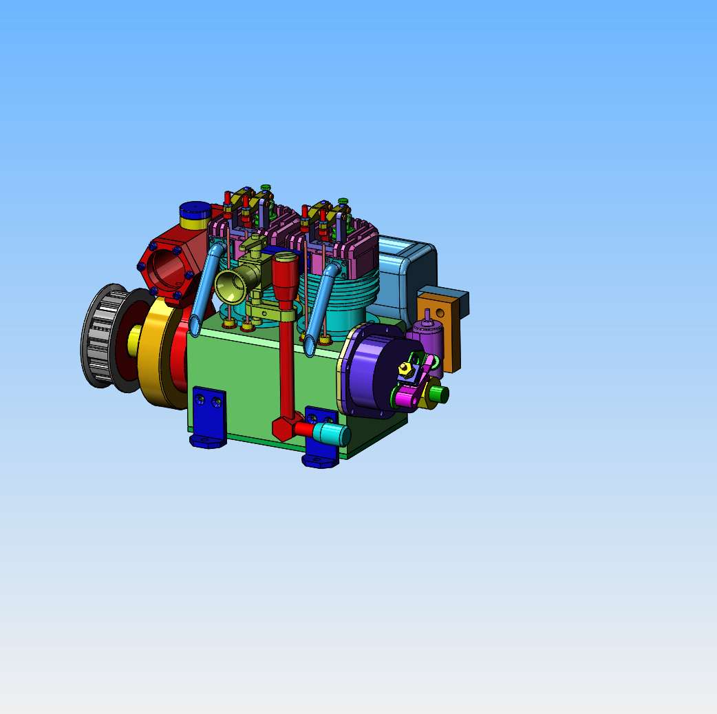
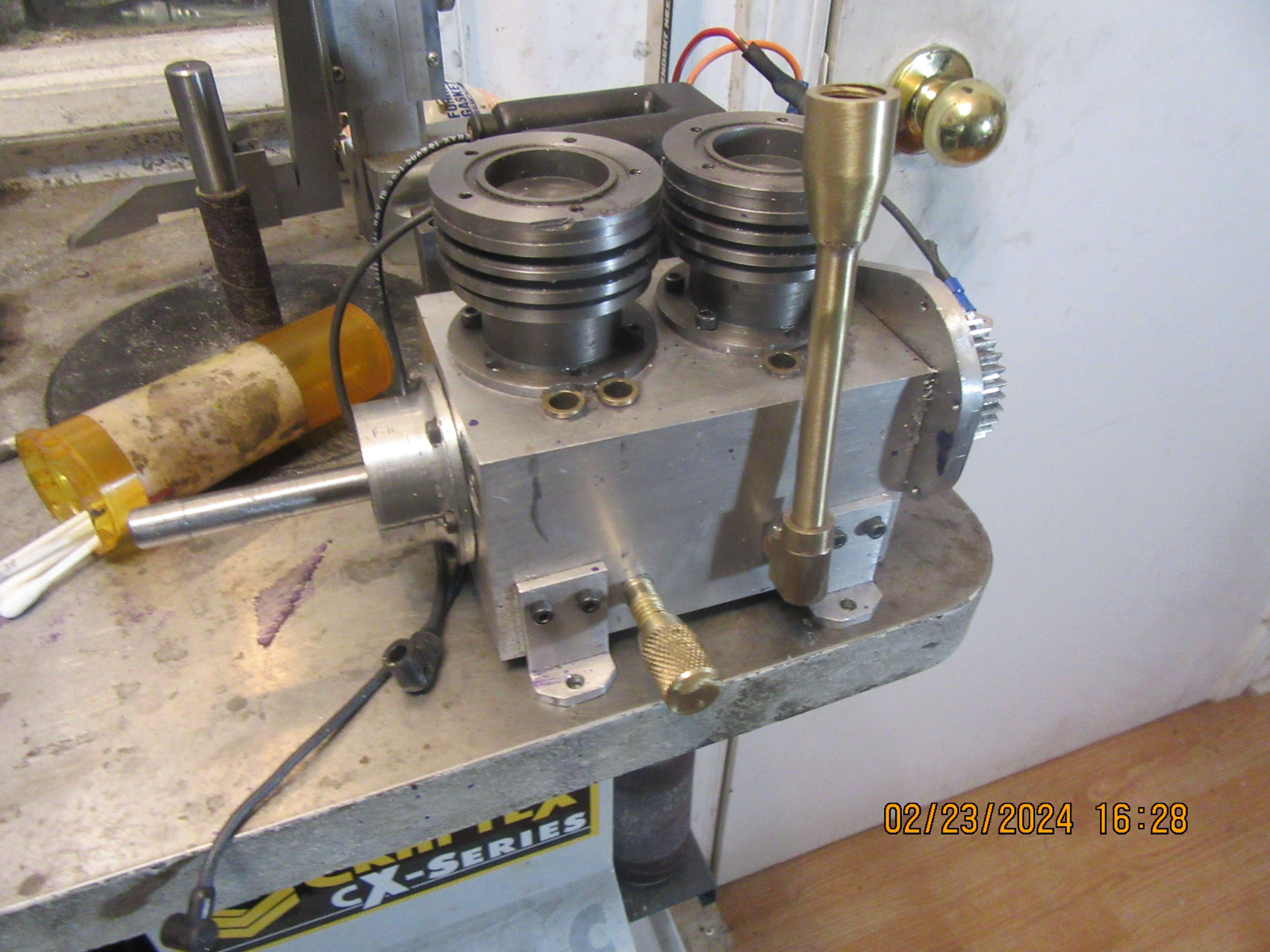
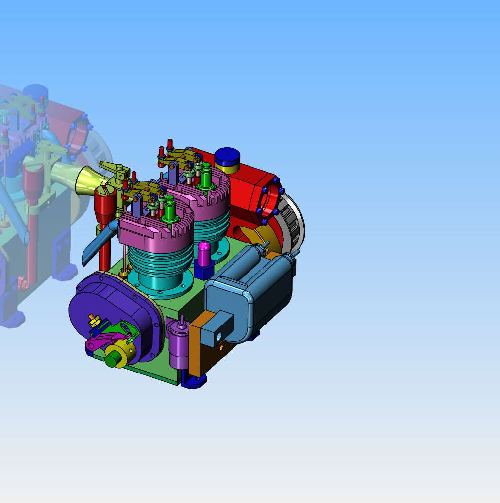
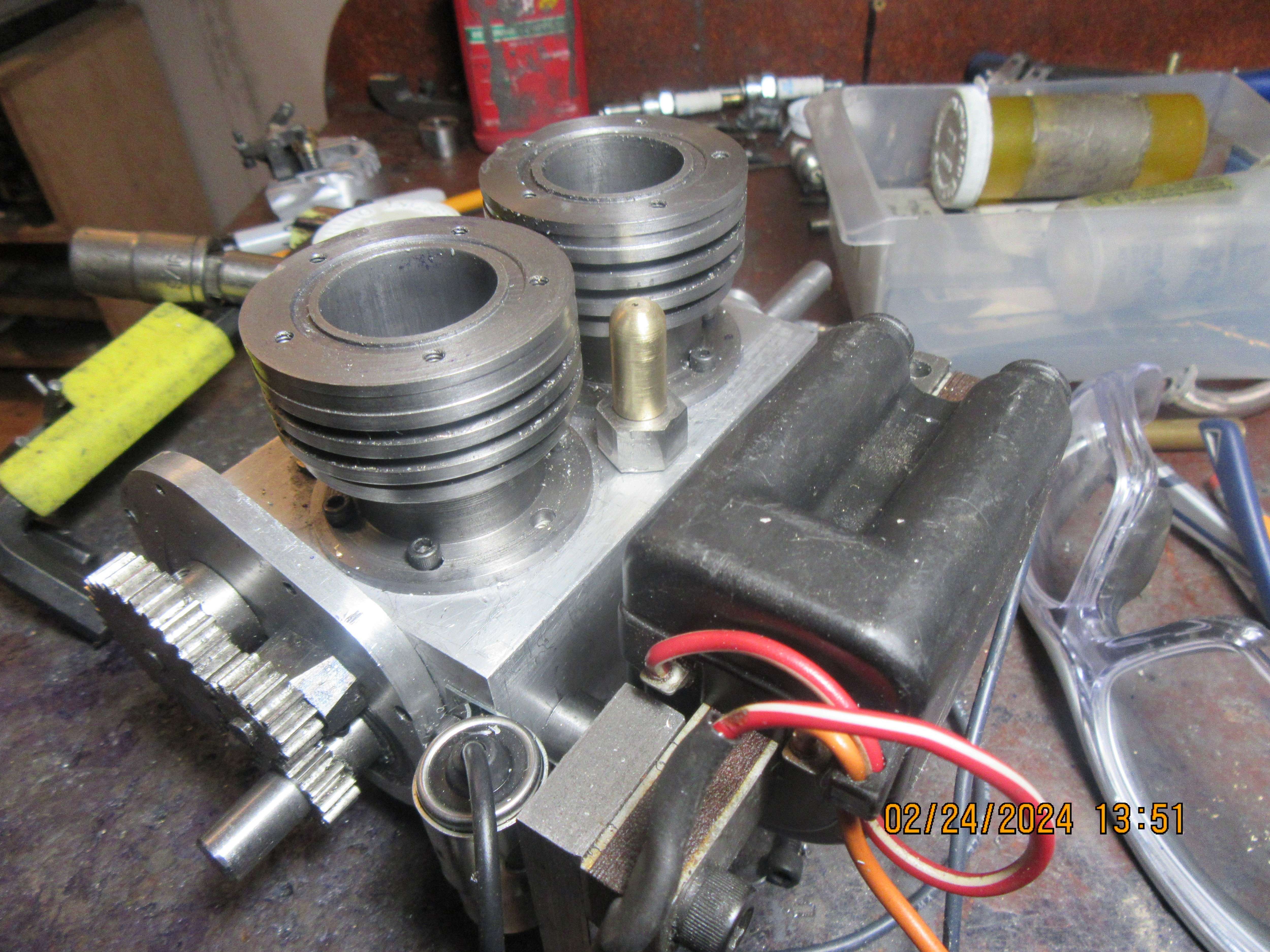
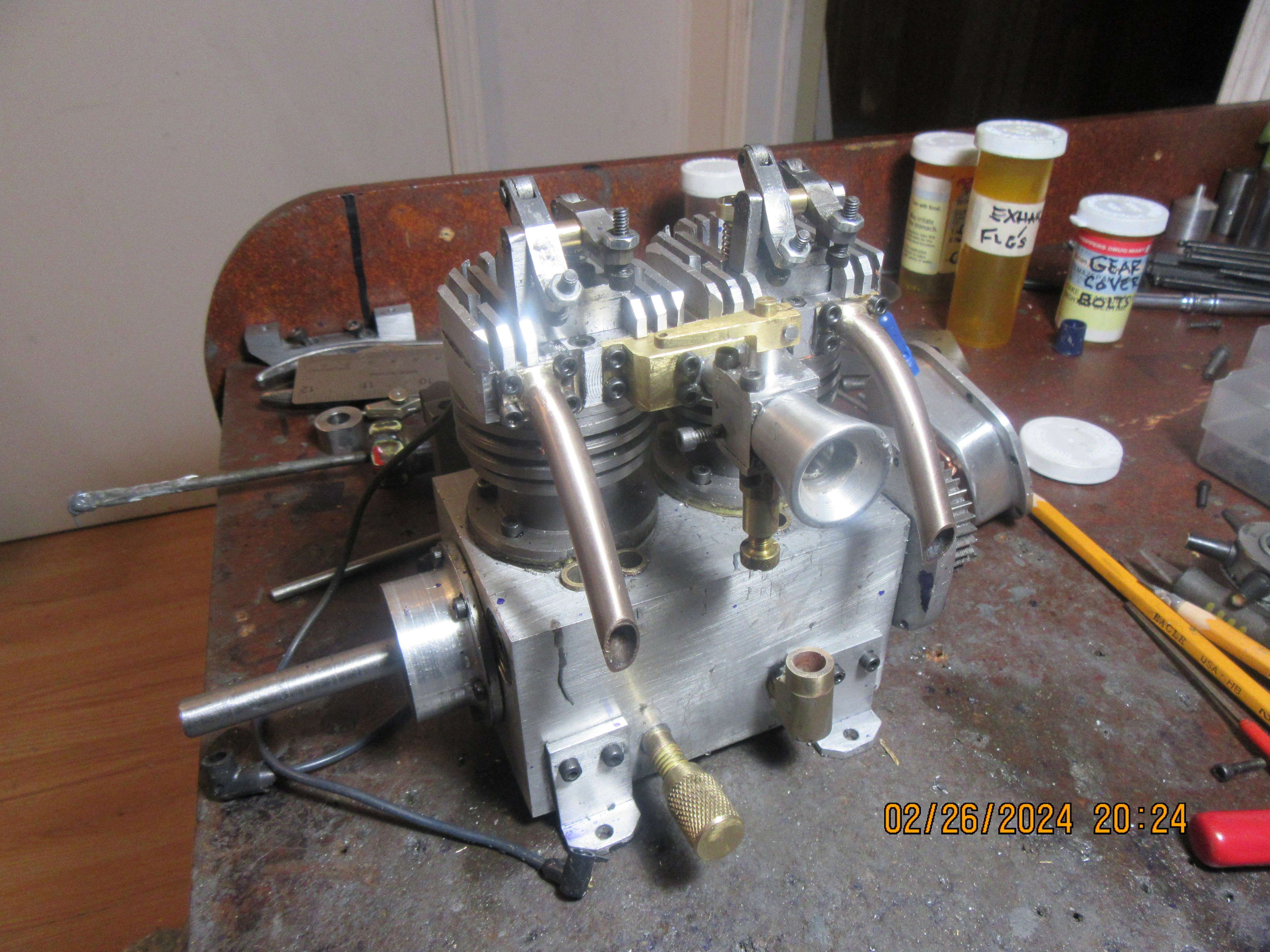
The time has come to think about the lubrication system for my engine. Since nothing inside the crankcase will be accessible when the engine is "buttoned up", it will have to be an "oil splash" lubrication system. At their lowest point the con rod caps are only 0.090" above the inner floor of the bottom sump plate. I plan on setting things up so that there is 1/4" of oil trapped in the engine above the sump plate. This should give good splash lubrication to the con rods and camshaft, without oil leaking everywhere out of the engine. I plan one gasket between sump plate and underside of crankcase, one set of gaskets where cylinders bolt to crankcase, and then the head gaskets. and one gasket where the gearcase bolts on.
 
Okay, I have the oiling system all sussed out. That red vertical pipe beside the carburetor is where lubrication oil is added to the engine. The way it works is that you pour what is calculated to be "more than enough" oil into the engine. Then you unscrew the bottom pipe cap and any oil that runs out leaves exactly 1/4" of lubricating oil above the top side of the sole plate.
3M8RLl.jpg
 
You might want to include a breather for the crankcase particularly as both pistons rise and fall together, there was one on the original engine.

Don't be tempted to just drill a hole in your filler cap as oil/air is likely to get pumped up the tube and go everywhere

Would be simpler to use the breather to fill the engine and then just have a bung in the side to level/drain.
 
Now I can get oil into the crankcase. I had to deviate a bit from my original design, but it worked out for the best. Both oil tubes are threaded and J.B. welded into the sides of the crankcase. No more work for me today, but I will have a look at the valve/ventilator/breather that I designed for a previous engine and see if I'm going to make it or not.
uzikwK.jpg
 
I hunted around in my engine files searching for a "crankcase vent". I remembered designing and making one, but I couldn't remember what I called it. I used my software's "search" function, and guessed at "crankcase vent" and it popped right up.
O1IPIi.jpg
 
I've just got enough room to fit this crankcase vent in between the cylinders on the back side of the engine. I agree, the pressure inside the crankcase is going to fluctuate wildly with both pistons moving up and down together. I guess I know what I'll be doing tomorrow.
uvUVcO.jpg
 
I've just got enough room to fit this crankcase vent in between the cylinders on the back side of the engine. I agree, the pressure inside the crankcase is going to fluctuate wildly with both pistons moving up and down together. I guess I know what I'll be doing tomorrow.
uvUVcO.jpg
I suggest a tweak to your breather: make the top a barb fitting for a bit of tygon fuel line, and route that to your intake downstream of the carb. This way the intake vacuum will assist in pulling the blowby gases out of the crankcase, and you'll reduce the emissions of oil mist when you run it.

I'm thinking of something similar for my model diesel, but a little worried it might run on its own oil and be impossible to stop...
If that is a concern - - - then a way to block off intake air is needed.
(I have been known to overload a diesel to stall it when it tried to do that!)
 
Todays work was to machine and install a crankcase vent, which has a ball and seat inside so that pressure can escape from the crankcase but can not be pulled into the crankcase as the pistons go up and down. At this point I think I am finished machining things for the engine, and can actually start with the final assembly.
7BAPE6.jpg
 
Today marks the point where I begin finished assembly of the engine. I need a gasket between the crankcase and the sump, one between the crankcase and the cylinders and one between the gear cover and the gearcase. The large Viton o-rings will act as the gasket between the cylinders and the cylinder heads, and gaskets at the exhaust flanges. As near as I can tell, I have built something every day between the beginning of January and the end (almost) of February and posted each day. My "assembly expert" which is part of my software informs me that I have 83 "unique parts" in the engine. I don't totally believe it, because I have shown a few of the bolts in the assembly and my software counts each bolt as a "unique part". I would be willing to bet though, that there are at least sixty "unique parts" not counting the bolts. As I've been going along with the build, a couple of times I've ran into problems and had to go back and change the solid models and the drawings to suit, but that is not terribly unusual. I finally got a firm appointment for my knee surgery on May 23. Canada has a great free medical and surgery plan, as long as you are ready to wait until you are scheduled for elective surgeries. I will have been waiting for this for two years.
 
I am sure that the Canadian system has some problems but the US system has a lot of people not getting medical at all care because they cannot afford even the copay.
 
Gordon--You are so right. As my wife and I get older and begin to get some of the "old folks" age related illnesses, we are so happy to live in a country that cares for it's old folks.---Even if it takes a long time.---Brian
 
Today was "Assembly day #1. Most unusual part was machining spacer rings to go between the cylinders and the crankcase. I didn't have enough clearance between the fully raised pistons and the valves, when the valves were fully open. While I had everything apart to do that, I put the Viton rings on the pistons. I used a little "high heat" silicone to anchor the larger viton o-rings in the groove at the top of the cylinders and bolted the heads on. Next step was to make gaskets for the exhaust flanges and bolt my exhaust pipe assemblies in place. This was very "picky" work, and the exhaust assemblies don't look nearly as good as they did on the solid model, but they are on there. Next step was to install the intake manifold, along with gasket onto the cylinders. This took far longer than it should have, but ultimately the manifold, along with gasket was installed, and lastly, the carb was installed. That doesn't look like much when you read about it, but I've spent 8 hours doing it. Tomorrow will be another assembly day, and I may finish up---or not.
KbY8Bh.jpg
 
I suggest a tweak to your breather: make the top a barb fitting for a bit of tygon fuel line, and route that to your intake downstream of the carb. This way the intake vacuum will assist in pulling the blowby gases out of the crankcase, and you'll reduce the emissions of oil mist when you run it.

I'm thinking of something similar for my model diesel, but a little worried it might run on its own oil and be impossible to stop...
Hi Nerd. I suggest you investigate your local scrap yard for car diesel engines, and look for the fitting between the breather pipe and intake manifold. Each manufacturer has a different way to control intake of blow-by gases. e.g. on a petrol engine, you can develop positive pressure from blow-by gases - then develop a full vacuum in the intake manifold when the throttle is closed. Thus a huge amount of blowby can be drawn into the intake - when there is no combustion so they are simply vented - and would fail the emissions tests for Hydrocarbons. So there is a small valve that operates to vent when the pressure if "right" but closes when the full vacuum is developed. Also the fuel canister - after absorbing fuel vapour from the the fuel tank into the carbon "capture" medium - then draws air through the canister when running to purge the canister. It has valves that operate when the pressure difference is "right" but prevents excess air being drawn through...
However, if you remember, Diesel engines run "full air" and throttle the fuel only by adjusting the fuel pump stroke. So you do not see full vacuum on a diesel. (Which is why they need an engine-driven vacuum pump for brake servos).
Does this help? - BUT Maybe model diesels are somehow different?

K2
 
Whats up for today?-- I can't put the sub plate on until the cam timing is set. I can't put the gear cover on until the cam timing is set. I can't set the cam timing until the pushrods are fabricated. Okay, today we make pushrods. This shouldn't be a really big deal because the pushrods are just lengths of hard steel rod.
 
I've worked all day and not accomplished much. I had to go down street and buy a piece of 01 steel and remake my tappets. They were made from some "mystery metal" that I had and seemed to want to "hang up" in the tappet guides, which are bronze. Tomorrow is a new day, and hopefully, I'll have some new ideas to go with it, other than putting on stiffer valve springs.
 
I've worked all day and not accomplished much. I had to go down street and buy a piece of 01 steel and remake my tappets. They were made from some "mystery metal" that I had and seemed to want to "hang up" in the tappet guides, which are bronze. Tomorrow is a new day, and hopefully, I'll have some new ideas to go with it, other than putting on stiffer valve springs.
Are the clearances just a bit tight?
 
Nerd--I've only been designing machinery since 1965. Clearance in a static environment is a set and non changing thing. Clearance in a dynamic environment is a moving target. Clearance on a bore for a tappet which is being acted upon by a cam sees just about every application of stress that you can come up with, plus eight or ten more.
 
Okay!!! The mystery of the day has been solved. If the cam is in the correct position under the tappet guide, then the tappet rides on the cam and goes up and down as the camshaft revolves. HOWEVER--If the cam is slightly out of position on the camshaft, then the tappet rides on the hub, and consequently it moves a little bit when it hits the setscrews in the hub, but nothing like it should when actually riding on the cam. This has only taken me half a day (or more) to figure out. I didn't think it was a clearance issue between tappet and tappet guide, but it took a lot of detecting to figure out what the heck was actually going on.
hELC7q.jpg
 

Latest posts

Back
Top