Something old, Something older---

Home Model Engine Machinist Forum

Help Support Home Model Engine Machinist Forum:

This site may earn a commission from merchant affiliate links, including eBay, Amazon, and others.

Brian Rupnow

Design Engineer
Project of the Month Winner
Joined
May 23, 2008
Messages
14,976
Reaction score
8,268
Location
Barrie, Ontario, Canada
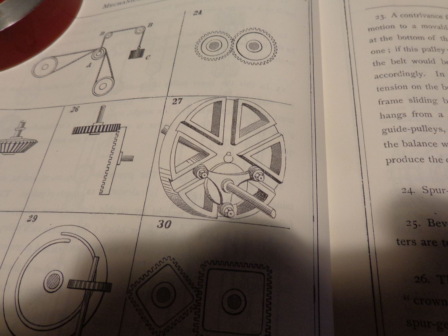
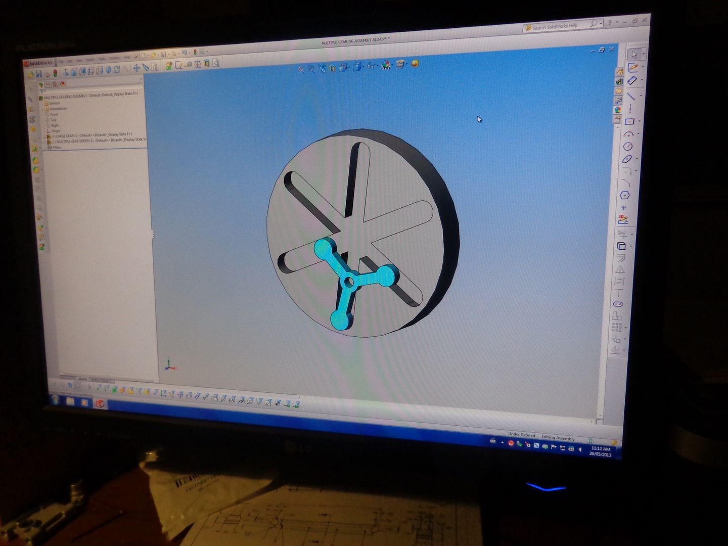
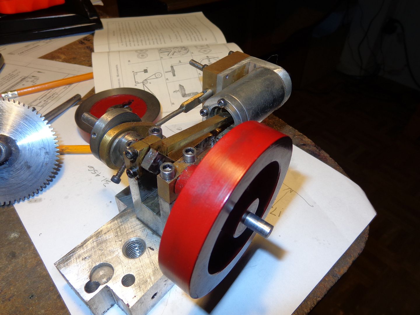
This morning its too cold to play outside, and I'm bored.--Which is not necessarily a bad thing. I have been perusing my booklet "507 Mechanical Movements" by Henry T Brown, looking for some kind of intriguing mechanical "eye candy" to possibly build. This is a little booklet choc full of all kind of nifty mechanical devices that were invented at the beginning of the mechanical revolution. Some of them were great devices, which are still in use today in modern machinery. Some are ideas that worked and were used for a period of time when mechanical things were transitioning from steam power to gasoline power, and some of them were probably only ever built once, just to see if they would work. A device that caught my eye this morning is item #27, which is listed as "Multiple Gearing" with the following description:--"A recent invention. The smaller triangular wheel drives the larger one by the movement of its attached friction-rollers in the radial grooves." There are no measurements nor geometric relationships given, only the picture shown here. I thought "Hmmmm---That's interesting!!! I wonder if I can replicate that and sus out the geometric relationships in Solidworks?" Good wife was still in bed sleeping, so I snuck downstairs to my office, fired up the computer, and found out that "By Golly, I can!!!" Of course the next question was, what do I have to run something like that? A static display just doesn't cut it. In my room devoted to small steam and gasoline engines which I have built over the last five years, there is the sad remains of what once was a very proud "Hit and Miss" air engine originally designed by Chuck Fellows over on HMEM. It ran marvellously, but I had cannibalized parts off it and used them for other purposes, and the main corpse has been laying around for two years now, waiting to be resurrected as something new. A few measurements and some deep thought has suggested that I should be able to use it as the main engine for a dynamic display of this marvelous old "Multiple Gearing" idea. So--as the summer advances and I get downtime from other work and play, I will be building this.----Brian


I have this nifty little book and half worn it out paging through it over and over again. I especially like the oval and square gears. We should all have a copy.

Mark T
 
Of course, nothing in life is easy. I lost all of the 3D cad models of this engine a few years ago when I had a major computer crash. Fortunately, I have many of the files of my different steam engines stored as pdf files on a web hosting site, so I was able to download a set of the plans and recreate all the solid models. When I first built this engine and made the drawings based on Chuck Fellows design, I posted the link as a free download, and I see that it has been downloaded 588 times. Now that I have recreated the models, I can move foreword with the "Multiple Gearing" design.
 
I went thru my random collection of spur gears today, and found a couple the right size for what I have in mind. Last night I decided that the determining factor on how big I made the large disc with the slots in it would be governed by how big a disc I can hold in the chuck on my rotary table. I checked tonight, and the largest is 4" diameter, so this works well with the 3.75" dia. that I had in mind. the design is basically done. Now all I have to do is find the time to make some parts!!!
 
Here we are at step #1. Two pieces of 1/4" brass plate, roughed out on the bandsaw, then finish turned in the lathe using the "double sided carpet tape" method. This is some of the brass plate that some gentleman in the USA so kindly sent me. One of the discs gets the slots cut into it--the other has a stub shaft silver soldered into the center so this thing can rotate when its all assembled.
 
Thanks you BRIAN, DNALOT and JWCNC, - sure helps to fill my mind with ambitious projects again now that I've just got a decent size lathe, - I think that there is enough stuff here to see me out!
 
Brian,

What software do you model with? That background color and fade looks like Allibre's default.

Just curious.
 
I know that the steam engine works. It worked as Chuck's Hit and Miss in its first life, then it was reincarnated as the "Doodle Bug". The part I'm not sure about is the "Multiple Gearing", so that seems like a good place to start. I centered my rotary table under the quill of my milling machine, and with the two pieces of brass still together, mounted on a short 1/4" dia. shaft, I mounted them in the 3 jaw chuck which lives on my rotary table. I wanted my angular divisions to be very precise, so I mounted the divider plates on the rotary table to get a good level of precision. I first drilled thru all the plates with the correct size drill for an 8-32 tap, then drilled clearance holes 1/4" deep thru only the top plate, then lacking a #8 counterboring tool, I used a 5/16" endmill to counterbore for the #8 socket heads. Then I tapped thru everything in place and inserted the #8 socket head cap screws. Then it was just a lot of "back and forth" with a 3/8" dia endmill until I was completely thru the top plate. You will see that the center area of the topmost plate is now gone, but I still have the 1/4" reamed hole in the second plate down.
 
Looks like you have made a good start on your "Radial Grooved Trammel"
I recall looking at the picture of the mechanism in my own copy of "1800 Mechanical Movements" and thinking it was a clever way of off setting two shafts, drive and driven.
Looking forward to your continuing build posts.
Ernie
 
Today I made up the shaft for what I am going to call the "star wheel" and got it silver soldered into place. Then I spent what seemed like an inordinate amount of time machining the "spider", and then careful measuring confirmed that I had "chuffed it up". One arm is perfect from center hole to hole in end of arm---One is .020" short, and one is .020" too long. I'm not sure how I managed that, but working of co-ordinate measurements in the mill without using the rotary table sometimes yields rather unusual results (for me). Its not a total loss though. The holes at the end of the arm are reamed 0.125". Tomorrow I will stop by my tool supplier and buy either a 5/32" or a 4mm endmill and move the holes around a little bit. Since I am making up the shafts that fit into the holes, I can do that. The shafts will be silver soldered into the spider, and I think that in order to work as intended, they have to be "spot on".
 
Well---I can say this much--IT WORKS!!! Its still at the dirty nasty stage, but a bit of time with the fine sandpaper and polishing buffs will take care of that. However, I have "driven" the spider around the starwheel by hand, and it actually does work the way I had hoped. At the last minute, I decided to use 638 Loctite instead of silver solder.
 
Brian,

Either the axle on the three pointed driver would have to move in a wierd pattern or the driven wheel. What kind of pattern does it make? Or am I all wet?

Your stuff is always amazing and I own a copy of that book as well.

"G"
 
You didn't give me a towel. :D It is a cool device, just have to find some work for it to do.

"G"
 
Back
Top