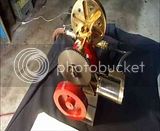
Something old, Something older---

Home Model Engine Machinist Forum

Help Support Home Model Engine Machinist Forum:

This site may earn a commission from merchant affiliate links, including eBay, Amazon, and others.
I don't think so. If you look at the typical crossed universal joint, when it's at an angle, it accelerates and decelerates twice in each revolution.


The axes are parallel, not at an angle like a UV joint. Surface speed, or as most machinist refer to it, surface footage, is a linear conversion of rotational speed based on circumference. Most tooling manufacturers will provide you with a recommended SFM as a starting point for feed/speed calculations.

Check out that PDF I put a couple posts up for formulas.
 
This has been the perfect size of project.---Start one weekend, finish the next weekend. Everything works very well, and gives me another shelf sitter, to go with all the other ones.!!!
 
That looks very good and it looks to be good runner :) Have you thought about painting the large pulley a different colour so that it would be easier to see the triangular piece's movements? Looks very good as it is, it was just a thought I had :)
Cheers,
sam
 
That looks very good and it looks to be good runner :) Have you thought about painting the large pulley a different colour so that it would be easier to see the triangular piece's movements? Looks very good as it is, it was just a thought I had :)
Cheers,
sam
Paint brass that can be polished??? Good Lord man, that's almost sacrilege. I see what you mean though.---Brian
 
Wonderful re-creation of this old mechanism!

I do apologize to everyone for adding this piece of almost non-relevant data before hand. I do not want to distract from Mr. Rupnow's great contributions to this fine forum.

That being said, it was pointed out by another member that the drive would suffer accelerations and declerations. There would be three such per revolution of the three legged member. The torque profile being sinusoidal in nature and having a max velocity point coinciding with the configuration where the three legged member has one leg fully inserted into its mating slot and the slowest velocity with that member in the position with two legs engaged an equal distance in the corresponding slots.

My math is VERY rusty, but the deviation would be a little less than 3%, as best I could figure it. Analytical Geometry is many decades in my past and my memory is akin to a block of swiss cheese these days.

But YES, a very sporadic drive method where consistent peripheral speed is desired, otherwise a beautiful symphony of mechanical motion and a joy to behold as it revolves.

Thank you for the wonderful creations Mr. Rupnow.
 
Black and white stripes and a strobe perhaps. Something like the markings found on those ancient things known as record playing turn tables?
I am guessing it is desired to measure the rotations and see the deviations?

:)
 
attachment.php


Yes. I'm sorry, I can't help but disagree on the speed change. While you have one pin ramping out of the the driven wheel you also have one ramping in. You can take several sample points along the path, calculate rotational speed. If it only had to driving pins at 180 degrees separation I would agree, but you have three with a minimum of two in contact at all times, while one is decelerating the other is accelerating at the same rate resulting in no change in rotational speed to the driven wheel.

I guess I could put pen to paper or either make one myself but that takes time that I'm short on. I'd like to see your calculus - that will convince me. I can't help but think if you were to graph this it would be a perfect parabola. I think at the point where the two driving pins are equidistant you would not have deceleration, you would have found the point where the two velocities happen to be exactly the same, one decreasing, one increasing. But for that one moment, the same.

This is the most I've had to think in a long time. I like it.

old mech.jpg
 
The output speed is constant. This needs no calculus. It is a simple matter of the geometry of an isosceles triangle.

Practically, of course, it has to be constant, or it would not work.

If a spider arm is at angle x from the bottom, its follower slot is at x/2.

Theoretically, the spider could have any number of arms, given an equal number of diametric grooves in the follower.

strange triangulated drive.jpg
 
Last edited:
I used a differrent analytical approach from the old school I was 'learned' in. The mesh of two gears can be simplified into two smooth surface cylinders and speed is calculated from the mesh surface radii. Normal toothed gears have a very small variation in mesh surface radii that is normally ignored in calculating the ratio between them. The mesh surface radii in this case is substantial and the difference between the contact radius when two 'teeth' are engaged equal distance in the slots versus when one tooth is engaged at full depth in the slot is large enough to make a noticeable difference between the driving speeds at those points.

I agree, this has made me think and I am enjoying it immensely.

I may have to model this myself just to find out. :)
 
The output speed is constant. This needs no calculus. It is a simple matter of the geometry of an isosceles triangle.

Practically, of course, it has to be constant, or it would not work.

If a spider arm is at angle x from the bottom, its follower slot is at x/2.

Theoretically, the spider could have any number of arms, given an equal number of diametric grooves in the follower.

First, thank you for confirming what I was already thinking. However, I disagree with your triangle approach as proving a relationship between the angular speed of both wheels. It only proves the relationship for any given Φ that there is an equilateral triangle thus proving the relationship of the pins to the diametric slots.

You can set up any triangle you want, only Φ and opposite are static.
attachment.php


Imagine the spider has one pin. Will the speed of the driven wheel vary in that situation as the pin distance to center of the driven varies?

Triangle on the left, pin is farther from driven center, triangle on the right, closer:
attachment.php


To prove they have the same angular speed you need to set up an equation to determine the angular speed of the larger driven wheel while the pin is traveling from closest to center and vis versa while it is traveling from farthest to closest.

Like calculating cutting speeds around a blended radiused corner to get constant surface feed.

any triangle.jpg


any triangle2.jpg
 
I think you are blinding yourself with science.

You agree there is a linear relationship between the angles. For a constant angular velocity of the spider, you can graph the follower angle over time. Start with both at the bottom, and call the angle zero. Whatever the spider angle is at some later time, the the follower angle will be half that. It will be a straight line graph. The slope gives you the (constant) angular velocity of the follower.
 

Latest posts

Back
Top