What is the life expectancy of the relay? I thought they couldn't cycle but so many times -- ??

You are using an out of date browser. It may not display this or other websites correctly.
You should upgrade or use an alternative browser.
You should upgrade or use an alternative browser.
Model engine CDI easy and cheap
- Thread starter bluejets
- Start date


Help Support Home Model Engine Machinist Forum:
This site may earn a commission from merchant affiliate
links, including eBay, Amazon, and others.
What is the life expectancy of the relay? I thought they couldn't cycle but so many times -- ??
It is using just the coil so life expectancy of a relay doesn't come into it
Ah, that's interesting. I had missed that.It is using just the coil so life expectancy of a relay doesn't come into it
As #180, have added the EDA files here for anyone interested.
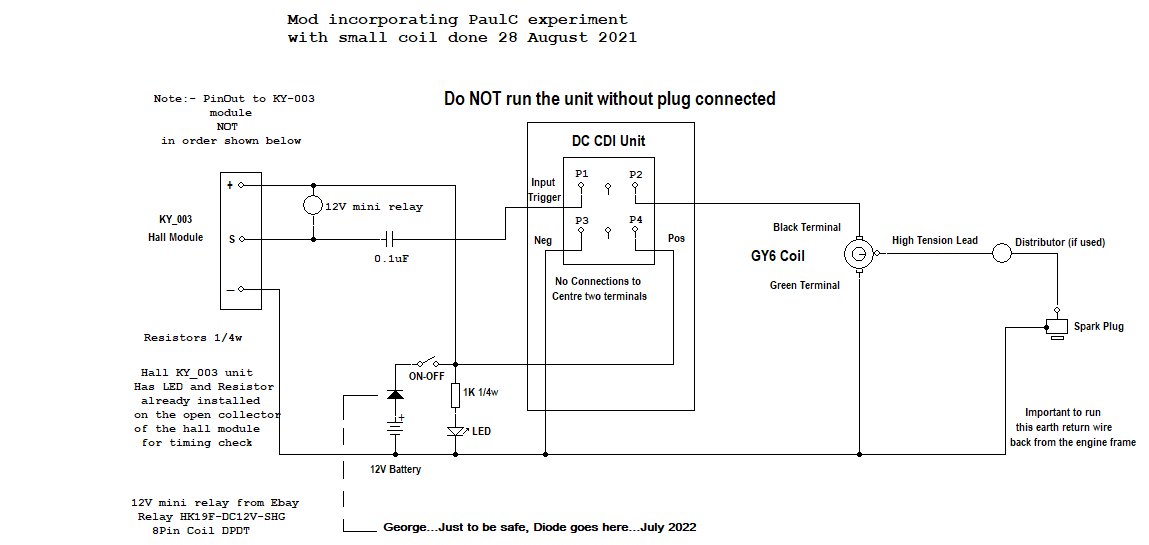
Also the final schematics for Hall Effect KY-003 module operation.
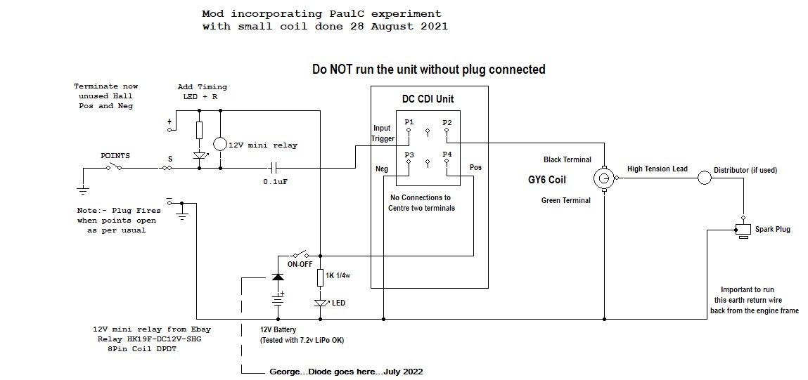
Have also included a version schematics for operation with everyday points if anyone so desires.
Note there is no requirement for the "points condensor" as in Kettering system.
Added one of these units to my old Atkinson engine yesterday and results are really good.
Might pay to note that I ran this points unit on 7.4v LiPo battery and it works fine even at that level.
Must remember though it's max rev requirements are probably 2000 rpm and would suit many old timer engines.
Forgot to add value of resistor for the timing LED in the points schematic....... 1k0 1/4w ...cheers
Also the final schematics for Hall Effect KY-003 module operation.
Have also included a version schematics for operation with everyday points if anyone so desires.
Note there is no requirement for the "points condensor" as in Kettering system.
Added one of these units to my old Atkinson engine yesterday and results are really good.
Might pay to note that I ran this points unit on 7.4v LiPo battery and it works fine even at that level.
Must remember though it's max rev requirements are probably 2000 rpm and would suit many old timer engines.
Forgot to add value of resistor for the timing LED in the points schematic....... 1k0 1/4w ...cheers
Attachments
MarkySparky
Member
Does anyone have the 12VDC CDI module drawn up with a BOM and gerber files and the like? I want to make my own circuit board for an old hit and miss oil jack pump engine. I cant tell you how long I have been looking for this! Please advise.
Thanks in advance.
- Mark
Thanks in advance.
- Mark
I have but it may be protected info.
Anyhow, you won't even start to build it for the price you can buy the complete system, coil and all.
Many have tried their own uC cdi's in the past with varying levels of success/failure, the latter more prominent.
74Sprint (Ray) I think is currently working on yet another approach, as yet unfinished as far as I know.
Details of that are in the forum here.
- Joined
- Sep 2, 2011
- Messages
- 1,342
- Reaction score
- 360
Lloyd, i just now was reading this thread and saw your post. several years ago i was a member of the technology council in SW Virginia and there was mention of someone using technology for the chicken door opener. if i recall the Gov. of Va at the time was even at that meeting. i want to say it was Dutt and Wagner they were mentioning as the egg producer but i could have just assumed that since they are just down the road from me and where the meetings were always held. just sounds like to much of a coincidence that this had to be you that they were talking about. this had to be at least 10 years ago i guess but seems like yesterday.Come on now, don't go talking bad about my chicken projects. It was something far more sophisticated than a simple "Chicken Waterer". It was a "Solar Synchronized Chicken Coop Door Opener". It had to be sophisticated to make up for the deficiencies in the tiny chicken brains. The door had to be coordinated with the seasonal variations in solar sunrise and sunset. The clocks in chickens are embedded, and cannot be re-programmed. Dusk to dawn timers won't work either, and the chickens will either get trapped inside or outside, and always on the wrong side. And several safety interlocks are necessary so that no chickens get mashed in the operating door. In the end, I don't think the chickens cared one way or the other.
i see your location is Charlottesville VA so maybe it was you. but i do recall this being mentioned as a huge inovation and how technology and farming were coming together.
Wow, small world. No, that wasn't me, although I went to VaTech and lived in Floyd County and know my way around that region. Beautiful country, but so is Charlottesville.Lloyd, i just now was reading this thread and saw your post. several years ago i was a member of the technology council in SW Virginia and there was mention of someone using technology for the chicken door opener. if i recall the Gov. of Va at the time was even at that meeting. i want to say it was Dutt and Wagner they were mentioning as the egg producer but i could have just assumed that since they are just down the road from me and where the meetings were always held. just sounds like to much of a coincidence that this had to be you that they were talking about. this had to be at least 10 years ago i guess but seems like yesterday.
i see your location is Charlottesville VA so maybe it was you. but i do recall this being mentioned as a huge inovation and how technology and farming were coming together.
The automatic chicken door was just one of those compulsive projects that you put a stupid amount of hours into and it turns out good, but was it a sensible use of your time, LOL. That door is still working with no repairs and no mashed chickens. It had remote LEDs that were visible from a window in the house to show if the door was open or closed or in operation. Fun stuff for sick minds.
Deleted, sorry, wrong post.
Lloyd
Lloyd
Last edited:
I'm sorry guys that I haven't done much on the programmable ignition lately but the wife has laid down the law with me after I bought 2 snowmobiles. They weren't running but I worked a little magic on them and they fire now but, all the fuel lines need replacing and carbs need to be cleaned, real bad. Anyway I have been working on the yard and house and when that is done I'll finish the programmable ignition. Interesting, both sleds have AC-CDI ignitions with fixed timing and have very little adjustment . . . . for now. TTYLI have but it may be protected info.
Anyhow, you won't even start to build it for the price you can buy the complete system, coil and all.
Many have tried their own uC cdi's in the past with varying levels of success/failure, the latter more prominent.
74Sprint (Ray) I think is currently working on yet another approach, as yet unfinished as far as I know.
Details of that are in the forum here.
Cheers
Ray
MarkySparky
Member
BLUEJETSI have but it may be protected info.
Anyhow, you won't even start to build it for the price you can buy the complete system, coil and all.
Many have tried their own uC cdi's in the past with varying levels of success/failure, the latter more prominent.
74Sprint (Ray) I think is currently working on yet another approach, as yet unfinished as far as I know.
Details of that are in the forum here.
I am not trying to make this for $. I am trying to get an old engine working again for my father's farm. The CDI module I built only works from a plug-in transformer. I want to just build one DC CDI. I don't want to buy it. I know it sounds stupid to everyone that reads this statement, but I just need to build it. if you can help at all my email is [email protected]
Just a bit of an update on what I have been doing. To start with I haven't given up on the programmable ignition, it's right in front of me but, I have been helping out a fellow member (Mark Hamilton) get a more reliable CDI ignition for his 120 year old (I believe) horizontal engine. At the same time I'm trying to work the bugs out of my Sparky-1 CDI ignition and Mark is helping with that by testing it.
When I designed the board and I wanted to try something out with the copper pours on the board. I never really measured the output of this little board and others told me "oh the spark isn't that strong", well they were way off and didn't know squat. Turns out the board is arcing out across 0.070" to the on board ignition coil at between 500-700 volts. I will have to redesign the board the right way. Bread boarded the primary voltage goes to 1,100 volts on 5 volt power supply. Right now using 12.5 volts power supply the current draw is only 0.034 amps! No that is not a typing error. This brings another problem, Mark is using 2 x12 volt truck batteries that are solar charged. The circuitry was never designed to use 12.5 volts, it was meant for 5 volts. So the power output is way to high, never thought I would say that.
I use a CC/CV power supply to limit the current, otherwise it tends to burn things up. We have been looking around to find a cheap current limiter and have tried a few things but, nothing we have tried so far works out. So I'm going to try and design a current limiting circuit I have seen before. If that works then I'll string everything together.
One thing Mark had asked for which, keeps the ignition that he has now and to keep the engine in 1 piece is a RPM limiting cutout circuit. The cutout needs to trip at 500 RPM and remove power to the ignition and stay locked out. Getting something to stay running at 15Hz but trip at 16Hz was not easy (wasted spark). So 450 RPM is ok but, 480 RPM is not. Anyway I ended up using a Frequency-to-Voltage chip (LM2907N-8/NOPB) that is used to make tachometers and it works beautifully and has adjustable trip limit. The chip will work with different signals but can be sensitive to different waveforms. I also found the datasheet and it's formulae to be out to lunch, most of the time. But if you want to make your own tach then this is the chip to use. For the cutout relay (latching) I'm using the standard automotive 30 amp 5 pin relay. You know the pin 30 and 87a stuff. Current draw on this circuit alone is 0.134 amps at 12 volts.
The image below shows the 16Hz (on) and the 2 LEDs show trip limit and cutout on. I don't have a momentary N/C switch in there, I just turn the power off to reset.

There are other ways to use this circuitry as a cheap rev limiter on almost any ignition. Next thing to do is the current limiting circuit and a new board design.
Cheers
Ray
When I designed the board and I wanted to try something out with the copper pours on the board. I never really measured the output of this little board and others told me "oh the spark isn't that strong", well they were way off and didn't know squat. Turns out the board is arcing out across 0.070" to the on board ignition coil at between 500-700 volts. I will have to redesign the board the right way. Bread boarded the primary voltage goes to 1,100 volts on 5 volt power supply. Right now using 12.5 volts power supply the current draw is only 0.034 amps! No that is not a typing error. This brings another problem, Mark is using 2 x12 volt truck batteries that are solar charged. The circuitry was never designed to use 12.5 volts, it was meant for 5 volts. So the power output is way to high, never thought I would say that.
I use a CC/CV power supply to limit the current, otherwise it tends to burn things up. We have been looking around to find a cheap current limiter and have tried a few things but, nothing we have tried so far works out. So I'm going to try and design a current limiting circuit I have seen before. If that works then I'll string everything together.
One thing Mark had asked for which, keeps the ignition that he has now and to keep the engine in 1 piece is a RPM limiting cutout circuit. The cutout needs to trip at 500 RPM and remove power to the ignition and stay locked out. Getting something to stay running at 15Hz but trip at 16Hz was not easy (wasted spark). So 450 RPM is ok but, 480 RPM is not. Anyway I ended up using a Frequency-to-Voltage chip (LM2907N-8/NOPB) that is used to make tachometers and it works beautifully and has adjustable trip limit. The chip will work with different signals but can be sensitive to different waveforms. I also found the datasheet and it's formulae to be out to lunch, most of the time. But if you want to make your own tach then this is the chip to use. For the cutout relay (latching) I'm using the standard automotive 30 amp 5 pin relay. You know the pin 30 and 87a stuff. Current draw on this circuit alone is 0.134 amps at 12 volts.
The image below shows the 16Hz (on) and the 2 LEDs show trip limit and cutout on. I don't have a momentary N/C switch in there, I just turn the power off to reset.
There are other ways to use this circuitry as a cheap rev limiter on almost any ignition. Next thing to do is the current limiting circuit and a new board design.
Cheers
Ray
Update for the original CDI Easy and Cheap.
Recently found that some find the soldering on the small pads difficult and they sometimes damage the pcb traces.
Seemed ok for me though but I just didn't want to have to add the leads for everyone so re-design easier.
Decided to update the CD add-on board to make physically a bit larger and make pads and traces more robust.
Version 1 is obviously the original and V2 the new design.
Same layout, just bigger for "all thumbs".
Also included the Gerber zip file if anyone feels like getting a few made.
I just ordered the new V2 from JLCPCB and costs seem to have risen slightly when one invokes "panalize" (4 pcb per panel in this instance)
Still cheap as @ around AUD $15.00 delivered over 10 to 12 days.
GY6 coils can still be found for around $7 and same for the 4 pin CDI "black box module", with the KY-003 hall modules still cheap as.
Might add that there are approximately 30 of these now out there and running like clockwork.
Note they can be used with the hall effect module KY-003 or with your everyday set of home made points.
Drawings for both above here. #184..... cannot stress enough the importance of running the return ground line from the engine to the negative supply connections as shown.
Attachments
- Joined
- Dec 31, 2010
- Messages
- 783
- Reaction score
- 195
bluejets:
Was there ever a link posted for a CDI module that works with your circuit?
I know you mentioned that some don't work with your circuit. Perhaps even some from the same supplier.
It would be useful if you could post a link to get started. I can take my chances on supply reliability and suitability.
Thanks
The only reference to what you say as I can remember is, this is for the 4 pin DC CDI module which are all the same as far as I know.I know you mentioned that some don't work with your circuit. Perhaps even some from the same supplier.
It would be useful if you could post a link to get started. I can take my chances on supply reliability and suitability.
Obviously my circuit will not work with the HV (300-400v) 5 or 6 pin units.
One link is here anyhow, just about to order a few more.
In this instance from here at least, if one orders over AUD$15.00 worth, (3 or more) delivery is free.
All I have seen as well, have the blue connector with the 4 internal pins to which I solder whatever length leads I need.
If one wants to use a plug with these, it will be the 6 pin auto type plug 2.8mm.
https://www.aliexpress.com/item/1005003571737448.html
The plug_socket come as pairs....use the RHS with the assoc spades (4 not all 6) on the outer 4 locations.
A quick look at the circuit diagrams and the blue socket will soon make sense.
I would advise using the diode as shown in the drawings for reverse polarity protection for, as with many electronic devices, you do not get a second chance.
As a final note, the high tension cable from the coil is Belden HV test lead cable, soldered and heat shrinked to the original, now cut off ht cable.
Video link on testing.........
Attachments


Last edited:
- Joined
- Dec 31, 2010
- Messages
- 783
- Reaction score
- 195
Ok. Thanks for getting all the info together in one place. I'll order the stuff just to play around. That said my driver board (Sage / Gedde - presented elsewhere here) and a cheap COP coil is cheaper and smaller as a whole package. Also I've never run into a practical rpm limit with the coil driver. Besides that CDI's generally produce a very narrow spark whereas a typical coil is much longer duration - a good thing. Most CDI's try to compensate with a multi-spark arrangement.
But I'm always up to test various solutions.
Thanks
But I'm always up to test various solutions.
Thanks
Already posted a circuit and details on a cop type coil from a BA falcon...runs on 3v7 LiPo and NO driver required.Ok. Thanks for getting all the info together in one place. I'll order the stuff just to play around. That said my driver board (Sage / Gedde - presented elsewhere here) and a cheap COP coil is cheaper and smaller as a whole package. Also I've never run into a practical rpm limit with the coil driver. Besides that CDI's generally produce a very narrow spark whereas a typical coil is much longer duration - a good thing. Most CDI's try to compensate with a multi-spark arrangement.
But I'm always up to test various solutions.
Thanks
Obviously you missed it.
- Joined
- Dec 31, 2010
- Messages
- 783
- Reaction score
- 195
I had no intention of being critical. I applaud your efforts. I enjoy all means to an end.
I've seen a few posts here and there about using the three / four wire coils (driver included). Case in point post #112 by Eccentric. I might have missed your particular post .
Seems the way to go considering simplicity and size etc.
So, why did you pursue the CDI solution? Just curious.
I've seen a few posts here and there about using the three / four wire coils (driver included). Case in point post #112 by Eccentric. I might have missed your particular post .
Seems the way to go considering simplicity and size etc.
So, why did you pursue the CDI solution? Just curious.
Last edited:
Had a call from my mate the renowned Duke of Edinburgh Award winner George Punter yesterday and yet another of his creations now up and running on the modified off-the-shelf CDI system I designed.
1/4" spark plug and all.
Said he did the Toyota jump when it first fired up but then he admitted he went a bit too close to the plug lead connection.
I'll post a link to the video when he uploads.
1/4" spark plug and all.
Said he did the Toyota jump when it first fired up but then he admitted he went a bit too close to the plug lead connection.
I'll post a link to the video when he uploads.
Last edited:
As the heading says ...easy and cheap...bugger all to play with and go wrong...anyone can access the parts from anywhere in the world.I had no intention of being critical. I applaud your efforts. I enjoy all means to an end.
I've seen a few posts here and there about using the three / four wire coils (driver included). Case in point post #112 by Eccentric. I might have missed your particular post .
Seems the way to go considering simplicity and size etc.
So, why did you pursue the CDI solution? Just curious.
Can be put together by anyone with any wiring/soldering skills in a few minutes AND guaranteed to work first time, every time.
AS it suits the hall effect module, again easy and cheap.
No need for points manufacture if one so desires, just a 3 x 1.5mm magnet and the stationary module.
Similar threads
- Replies
- 0
- Views
- 246
- Replies
- 248
- Views
- 32K
- Replies
- 2
- Views
- 983
- Replies
- 61
- Views
- 8K