CNC x2 Mill

Home Model Engine Machinist Forum

Help Support Home Model Engine Machinist Forum:

This site may earn a commission from merchant affiliate links, including eBay, Amazon, and others.

Rndmann9

Well-Known Member
Joined
May 30, 2016
Messages
148
Reaction score
27
I'm finally getting around to designing and building my x2 mill! Been kicking this can down the road for a long time.

image.jpg
 
Looks good. Keep us posted.
You may want to consider replacing the solid coupling between the motor shaft and the lead screw with a flexible coupling at some point. It reduces any problems with shaft misalignment and keeps the motor bearing and the lead screw bearings from fighting with each other. Not that the solid won't work. Just makes life easier and often increases available power. Easy to obtain on Ebay to suit shaft sizes. Inexpensive if you shop around.
Gail in NM

s-l1600_50.jpg
 
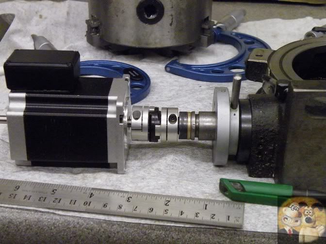
Unfortunately Gail, the only type of coupling to give total out of line control (within reason) is the Oldham Coupling.

These couplings automatically realign themselves by offsetting the acetyl disc whilst turning and cut out any side loads onto the bearings at each end.
I have been using them for many years with no problems at all.

DM31.jpg


DM32.jpg


In the UK you can easily purchase them from here, but you might also find them on auction sites.

http://www.arceurotrade.co.uk/Catalogue/Stepper-Motors/Oldham-Couplings

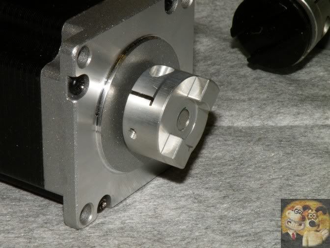
The type you have shown, will still allow side loads to the bearings even though they will allow you to connect to the two shafts, it is the deflected bend that does it, with the coupling trying to straighten itself out all the time.

If you are up to it, you can make Oldham Couplings yourself, but taking account of the time involved, it pays to cough up the cash and buy them.

BTW, if you can't get the correct sized ends for the shafts you are using, you can enlarge the centre hole, BUT ONLY BY BORING, otherwise if you just open them out with a drill, the holes can wander anywhere.
DAMHIK

John
 
Last edited:
Just two cents worth - I snapped a couple of the spring type couplers with table direction changes - Got the little spider type coupling - So far it's Me Proof . . . That, or I'm not trying hard enough to break it .

_61_zps1se9ibcy.jpg
 
John,
You are correct. The Oldham type coupling is far superior to the spring type that I showed.The spring type is OK for VERY MINOR misalignments and is a definite improvement over having a rigid type coupling. I showed it because it is inexpensive and very available in my world. But I agree the Oldham is a superior coupling.
Gail in NM
 
It's not really solid. I'm going to most likely buy one but designed one just in case. Doing some more machining today but it's hot in the shop....so hopefully have some more pics up soon.
 
The one I designed looks remarkably like the one in blogwitch's pic.
 
I'm also not showing the thrust bearings that I will add between the mill body and motor mount block. Haven't decided how I want that yet. I need to get some in my hands to see so I know how I want to add them in. I have an idea but it resides in my head for now.
 
What's the length of those couplings just out of curiosity ? I need it to be around an inch. This was the concept so far.

image.jpg
 
Gail,

You are quite correct about the spring type couplings, they are much cheaper. The 1" Oldham ones cost me, in your money, about $30 for each complete one. But I always look on them as being good insurance, never need to be looked at again.

R,

If you follow the link I gave to Arc Euro, on that first page, it gives the general sizes of the component parts for each size OD.

John
 
Last edited:
I'll check it out. Been roughing out the part that mounts to the mill.

image.jpg
 
I decided to thicken the stepper side a bit so I could recess the screws.
 
Another milestone perhaps more important than the mechanics. Got the brains working I'll get it all tuned up once I get everything put together hopefully soon. Turns out there is a free cam generator add on with one of my drafting programs I use for work so that is an awesome thing (autodesk inventor- with hsm). I work in construction and use revit on a daily basis but inventor is part of my software suite and I use it a lot at home. If your not familiar with it it's awesome for mechanical design. You can model stuff and then make it work before building it. What I did the above models in. ^
 
Little further along. Y assembly is almost finished. Prob start x tomorrow hopefully.

image.jpg
 
Actually I'm kinda leaning towards an angular contact bearing now since it would act as a mix of thrust and roller bearing. 5201 I think is the size I'm looking at at least for the y axis. I would just have to bore the diameter and depth in the end of the t shaped. Piece pictured above.
 
. . . I would just have to bore the diameter and depth in the end of the t shaped. Piece pictured above.

The Y has me thinking . For the X I used a couple of thrust bearing on the right side [might be overkill] - Bored into the existing retainer, each side leaving a web in the middle - Hand crank lock nut does the holding. Other end (stepper end) has one of the regular bearing types to keep shaft and stepper aligned. The Y . . . Only one end has bearing support and not a lot of room to work with . . .

DSCF0018_zps5syyc1fm.jpg


Something will come up . . .
 

Latest posts

Back
Top