I just shocked the living Hell out of myself messing around with this used $10 dual output coil I got the other day. There is more going on here than I know. If it will give me a kick like that, it should certainly fire a sparkplug. I think that a more sophisticated test rig is called for now, other than touching two wires together. Incidentally, the positive feed goes to the red wire with the white stripe. The orange wire goes to the points, then to ground. I'm not 100% sure that the steel laminated bar through the middle has to be grounded or not, but I am going to assume "probably". After I make the last part tomorrow to modify the intake manifold, I will make up a test rig with two real sparkplugs in it and let you know the results. I will also make up a steel "horseshoe" that attaches to both ends of the laminated steel bar to see if that has any effect on the strength of the spark.

You are using an out of date browser. It may not display this or other websites correctly.
You should upgrade or use an alternative browser.
You should upgrade or use an alternative browser.
Opposed Twin I.C.
- Thread starter Brian Rupnow
- Start date


Help Support Home Model Engine Machinist Forum:
This site may earn a commission from merchant affiliate
links, including eBay, Amazon, and others.
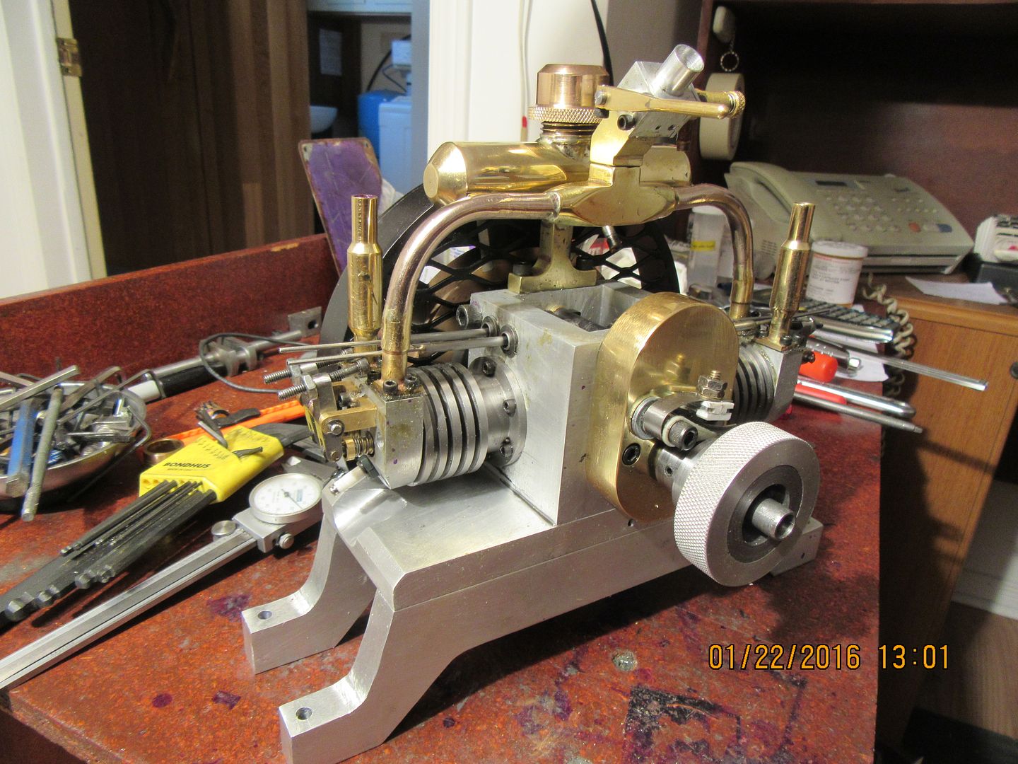
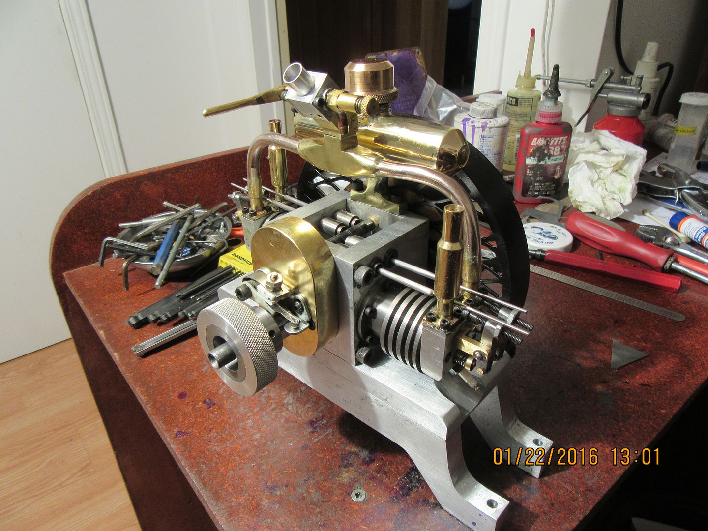
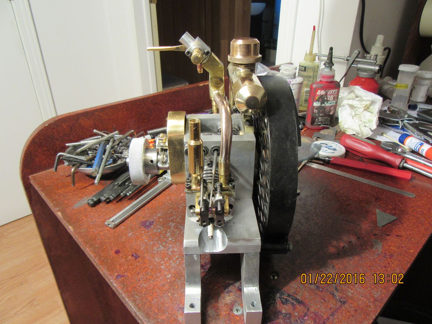
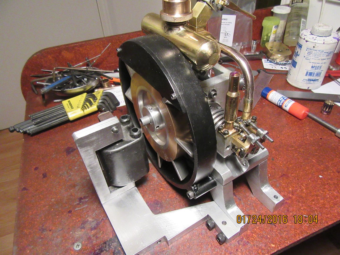
Well, there it is--mechanically finished!!! The pushrods for the rocker arms aren't cut to finished length yet, because I still have to "phase the camshaft" and Loctite the individual cams to the shaft. The gas tank is finished, and all the gaskets are in place. The carburetor clears everything very well with the 45 degree adapter I added between the carburetor and the intake manifold. I think this is the prettiest engine I've built yet. The next big "sorting out" will be the dual output coil and the camshaft phasing. We are getting very close to trying to start this thing.--I won't say a "running engine"---that would be tempting fate!!!


I built a steel "horseshoe" shaped bracket from 3/8" steel to mount the coil on, and using my spark gap tester and a spare sparkplug I have hooked everything up and seem to be getting good results from my used $10 dual output motorcycle coil. I didn't mention it in the video, but I was not using a condenser in this test. I did try with a condenser in the circuit after I made the video, and I think it improves the quality of the spark, but it is rather hard to tell.
[ame]https://www.youtube.com/watch?v=vhy0MA_8bKM&feature=youtu.be[/ame]
[ame]https://www.youtube.com/watch?v=vhy0MA_8bKM&feature=youtu.be[/ame]
Cogsy
Well-Known Member
Brian - I'm not sure how the gaps compare between your tester and the spark plug, but I noticed that around the 1:29 - 1:35 mark of your video the tester appeared to miss a couple of sparks and only the plug 'fired'. If the gaps are substantially different this may be the cause. I've never been overly fussed about plug gaps in model engines but I'm guessing you'll have to make sure yours are close to the same for each plug.
Waiting eagerly for the noisy video!
Waiting eagerly for the noisy video!
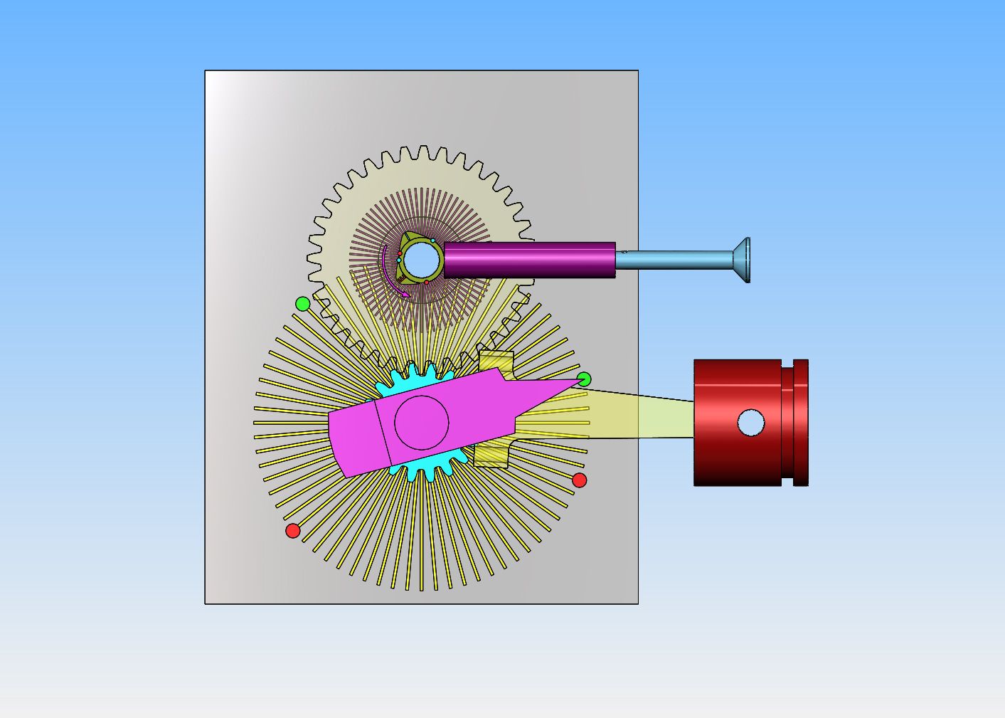
My next move is going to be Loctiting the cam segments to the camshaft, and this has me really nervous.---So nervous that I decided I had to make a 3D cad model of all the affected parts, then after all the appropriate mates were added drag the crankshaft around through 360 degrees a couple of times and watch the cam rotate at half the speed of the crankshaft in the opposite direction and see where the tangency points of the cam flank intersected centerline of the valve lifter. I have simplified my cad model by leaving out the pushrod and rocker arm, but the geometry still applies. This took me a goodly portion of the morning, and after doing it I discovered somebody had given me bad information about separation of the cam lobes!!!----WHAT!!!---COULDN'T BE!!! I decided to take a break and take my lovely wife for a drive down to Orangeville, where my daughter and her husband may buy a house.---I came home and decided to check everything on my cad layout one more time---and discovered I had made a mistake!! The information I was given about cam lobe separation was good. --So---Tomorrow is Loctite time!!
--So---Tomorrow is Loctite time!!
The individual cams are now Loctited to the shaft with #638 Loctite. The shaft was degreased with laquer thinners and sanded longitudinally with 160 grit garnet paper to give some "tooth" for the Loctite to grip. The inside bore of the individual cam segments were degreased with laquer thinners and a cotton swab to get any traces of oil out of the inside. The first cam slid into place was an exhaust cam, and the high point of the cam was held horizontal with the V-notched plate you see setting on the bed of the mill. the rotary table was set at the "0" mark. After a wait of 20 minutes to let the Loctite set up, the rotary table was rotated 102.5 degrees and the next cam, which was an intake cam was slid into place and again positioned with the v-notched plate. Since the third cam in was another intake valve, the rotary table was not moved---the third cam was slid on and positioned 180 degrees out of phase with the second cam in by using the v-notched stick from the opposite side. The rotary table was then indexed to the 180 degree mark and the final cam section slid into place. as you can see in the picture, it's a bit of a gooey mess right now.--That's okay though, because I don't want to wipe any Loctite away and accidently disturb the position of the cams. After a 24 hour set-up time, I will remove the shaft from the rotary table and scrape away any excess Loctite--(it cleans up quite easily with sandpaper).

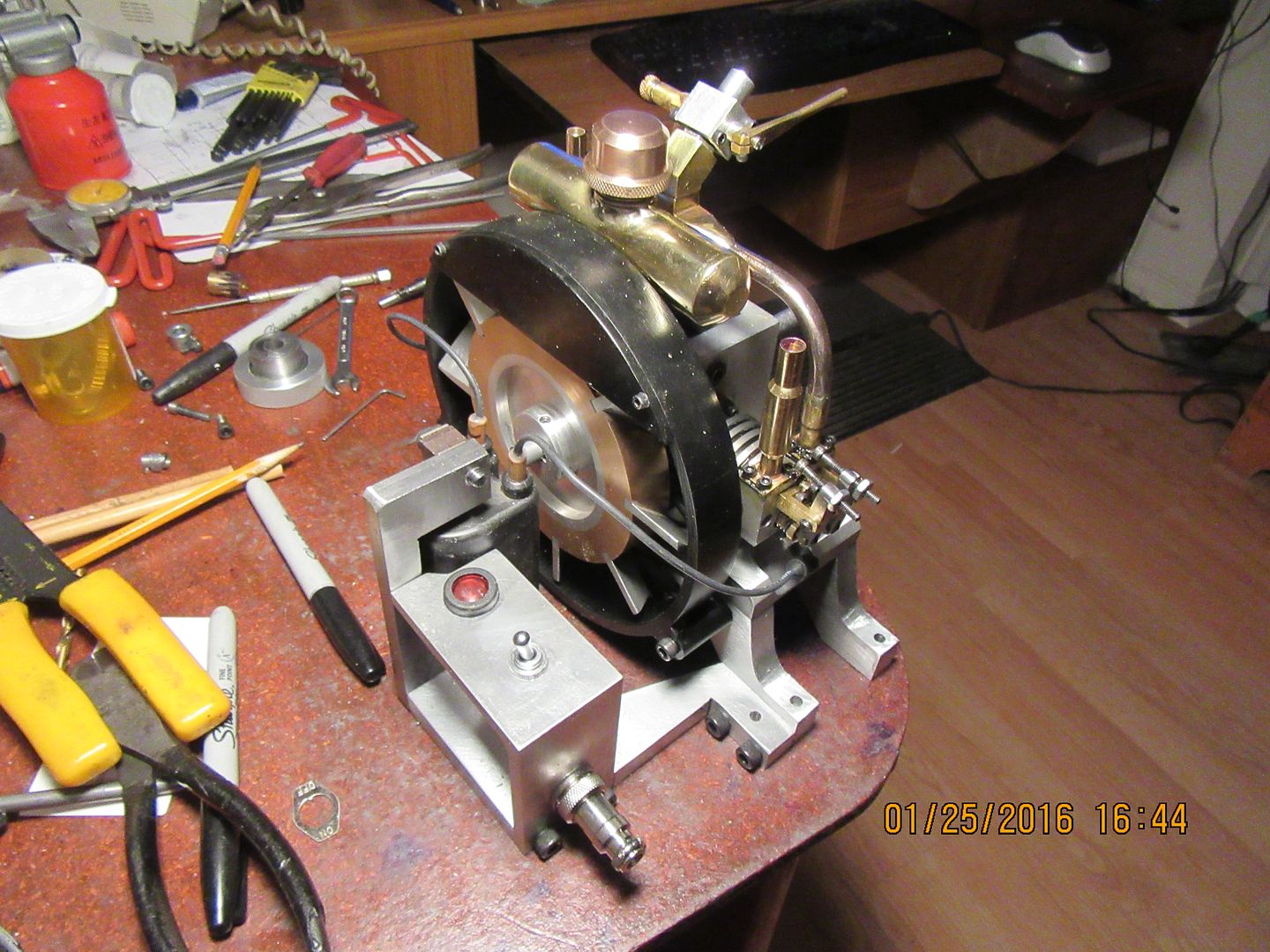
The dual output motorcycle coil is mounted to the back side of the engine. I have one angle bracket to finish and mount for the on/off switch. I removed the large diameter ignition wires from the coil (they simply pull straight out of the sockets.) The ignition wires for the very small Rimfire sparkplugs are only 0.100" in diameter, but I have discovered a nifty trick to use them with automotive ignition coils, or any coil that originally came set up for 0.284" (7 mm) diameter wires. I take a piece of hardwood dowel, turn the outside diameter to 0.284", and drill the center out with a 1/8" drill. Push the small diameter wire through the dowel with some bare wire exposed at the end that fits into the coil, and coat the last 1/2" of the other end where it goes into the wooden dowel with a bit of epoxy. Wood is a good insulator, and it works really well.

I woke up this morning with the horrible feeling that I may have screwed up the cam segment positions for the second cylinder. My intent with this engine is that the cylinders fire on alternate cycles. When piston #1 is at top dead center on compression, ready to fire, piston #2 should be at top dead center on exhaust stroke. So, it seemed logical that the second two cam sections should set at exactly 180 degrees to the first two cam segments and that's the way I Loctited them in position. Later in the day, when the Loctite had set up good, I put the camshaft back into the engine and turned it by hand to watch it's influence on the various valve lifters. As the cam rotated into position to begin lifting the intake valve on cylinder one, the cam right beside it which operates the intake valve on cylinder #2 also began to lift the intake valve on cylinder #2. I thought that seemed a bit unusual, but tucked the thought away into my belfry with the rest of the bats, and went on with other parts of the engine. This morning, as I lay awake in bed planning my day, the thought occurred---My theory of having the cams for the second cylinder at 180 degrees to the first cylinder was absolutely correct.---IF the cylinders had both been on the same side of the crankshaft. However, the cylinders are 180 degrees apart on opposite sides of the crankshaft.---so--today I will heat up the last two cam segments and rotate them 180 degrees.---I'm tellin' ya---This camshaft business is not for wimps or old ladies. I love learning new stuff, but this cam business has me stretched quite a bit beyond my normal limits!!!
cwelkie
Well-Known Member
- Joined
- Dec 19, 2010
- Messages
- 170
- Reaction score
- 60
So close Brian - looking very good!
I disagree with this though:
"I love learning new stuff, but this cam business has me stretched quite a bit beyond my normal limits!!!"
... you figured it out in the end. You continue to do (and share) things many of us wait for guys like you to do before we even try. Thanks for that.
Charlie
I disagree with this though:
"I love learning new stuff, but this cam business has me stretched quite a bit beyond my normal limits!!!"
... you figured it out in the end. You continue to do (and share) things many of us wait for guys like you to do before we even try. Thanks for that.
Charlie
Charlie---I don't mind figuring stuff out---I just wish I would figure it out right the FIRST time around.So close Brian - looking very good!
I disagree with this though:
"I love learning new stuff, but this cam business has me stretched quite a bit beyond my normal limits!!!"
... you figured it out in the end. You continue to do (and share) things many of us wait for guys like you to do before we even try. Thanks for that.
Charlie
---BrianToday we got on/off switch, indicator light, and plug in for wires to battery installed, and sparkplug wires in place.---and changed the position of the two cams that operate the valves on the cylinder closest to the flywheel. The switches aren't wired yet, that will be tomorrows job. At first I was going to wire the indicator light in series with the coil, then I decided that if I did that the light would blink off every time the ignition points opened.---So--I will wire it parallel to the ignition circuit. I will reinstall the cam tomorrow and start buttoning everything up.

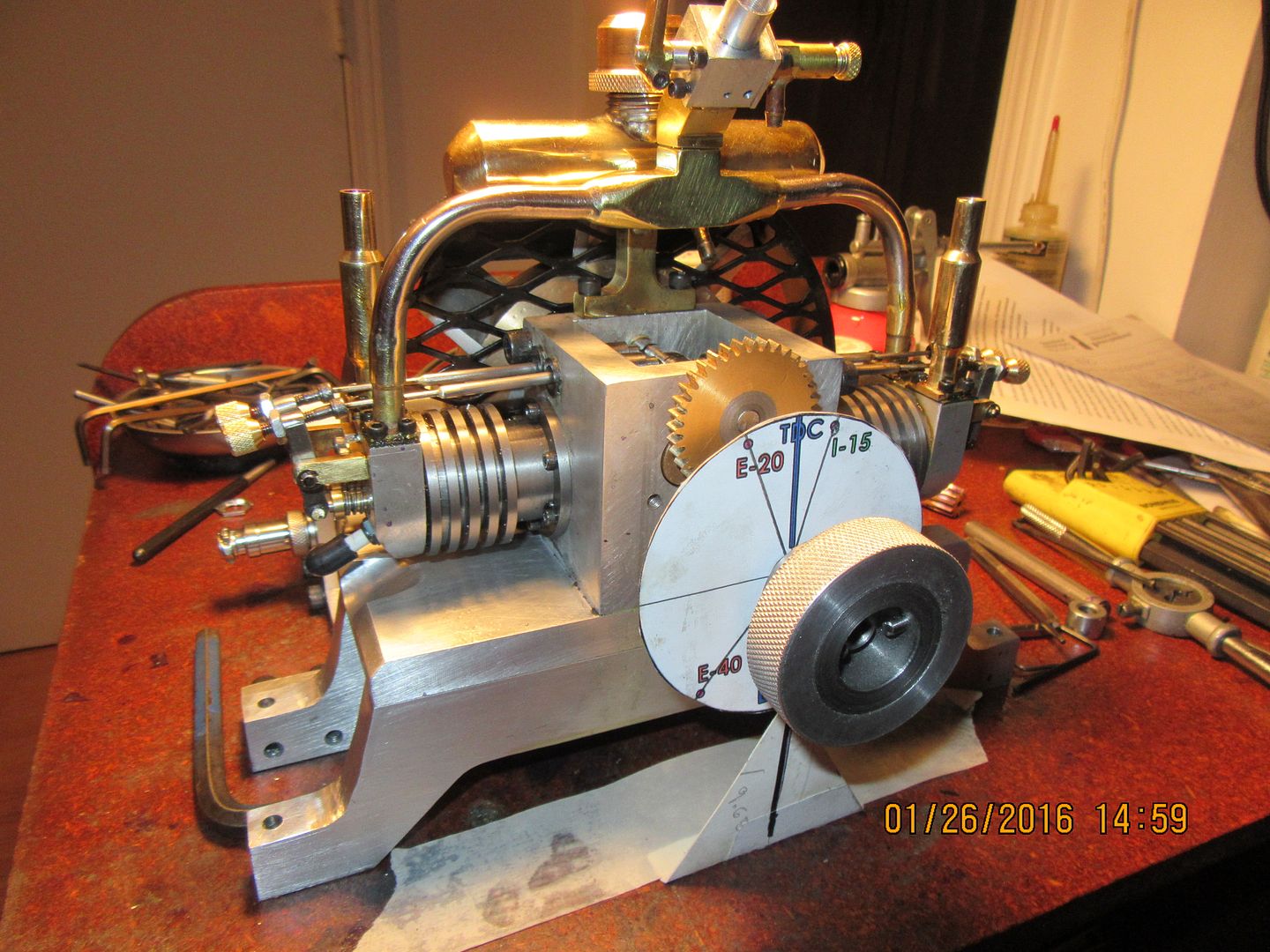
I'll tell ya right now!!--Setting valve timing ain't for sissies!!! I've been at this since I got up this morning, but some of the time was spent cutting the pushrods to length and adjusting the valve lash, some of it was spent machining knurled brass "handles" for the end of the valve lash adjusting screws, and a LOT of the time was spent setting valve timing, then , resetting it, and resetting once again. Things tend to move when you tighten them up. I may not have it absolutely dead nuts right, but it's mighty close!!!

After a long and somewhat tedious day, I have everything back together and buttoned up and seem to have reasonably good compression. This is a rather subjective thing at this point, because with the new Viton rings in place the engine is pretty stiff. I can feel considerable difference now with the valves set and the pushrods in place. Tomorrow I will tackle the wiring, and if all goes well, I may try and start the engine.
- Joined
- Sep 19, 2015
- Messages
- 274
- Reaction score
- 80
Although I'm not a machinists boot lace, I've been following along and I really like your build.
Best of luck.
I can't wait to hear it sing.
Cheers
John
Best of luck.
I can't wait to hear it sing.
Cheers
John
Thanks Johno---I'm always glad to hear from the Aussies.---Brian
Wiring is finished, and it's time to start the engine--I'm working on it right now. Have had a few exciting "pops and farts" but no joy yet. The heavy break-in oil that I had in the cylinders is fouling the sparkplugs before it has a chance to actually start and blow all the oil out of the cylinders. I just took it outside and with the sparkplugs out injected gasoline into both cylinders, swished it around good, 2 or 3 times repeatedly, then blew the cylinders out with my air hose at 100 psi. The engine is setting out in my main garage now, reeking of gasoline. I will let it dry out for an hour and then have another try. That was the only thing i didn't like about this design, was the sparkplugs laying almost at the bottom side of the cylinder. If the engine floods, or you have any residual oil in there, it fouls the plugs and then you can't clear them until you remove them from the engine and dry them off.
Okay--First round of "attempts to start" is over. Even after flushing the break-in oil out of the cylinders, it's not firing. I have double checked the sequence of the valve timing and the ignition timing, and they are right on spec. The sparkplugs are giving a nice crisp spark (At least when they are laying out on the cylinder head). Those exhaust stacks are positioned perfectly to do the old "Pucker up and blow your guts out" trick. If neither valve is up on the cam, and you can't blow down the stack while holding the exhaust valve open under finger pressure, that shows that your intake valve isn't leaking. If you can't blow down the stack while the intake is closed and the exhaust is open, that shows that your combustion chamber and head gasket isn't leaking. if you can't suck air thru the stack while holding the intake open and the exhaust is closed, that indicates that the exhaust valve isn't leaking.---Very crude and rudimentary tests, yes, but they do show up "gross leakage". Of course, nothing seals perfectly on a brand new unrun engine. It's all a matter of "degree" of leakage. I'm not ready to tear anything down yet. Next trick will be to put a pulley on it and drive it at about 500 RPM with my half horse electric motor, while tweaking the fuel mixture with the ignition "on" to see if I can get it to start firing.
canadianhorsepower
Well-Known Member
- Joined
- Oct 22, 2011
- Messages
- 1,671
- Reaction score
- 324
Brian,
to my opinion the intake runner are way to long for
such a small AND low RPM engine.
GOOD LUCK
to my opinion the intake runner are way to long for
such a small AND low RPM engine.
GOOD LUCK
Things are looking up!! with the engine being driven by my electric motor, I have tweaked fuel mixture and timing to the point where the engine is firing consistently on one cylinder, and inconsistently on the other. It is very cold and fairly dark out in the main garage and I've had enough for today. I think that now I have to play about with the ignition timing. The secret to this driving an engine with a motor is to get the engine firing, even if it's not running under it's own power. Every time it fires, it helps seat the valves a little more, until the combustion chamber becomes air-tight. Of course this won't fix badly ground valves, but if the valves are very "close" to being a good seal, this just adds the finishing touches.---more tomorrow.
Similar threads
- Replies
- 61
- Views
- 8K
- Replies
- 31
- Views
- 3K