


zeeprogrammer
Well-Known Member
- Joined
- Mar 14, 2009
- Messages
- 3,362
- Reaction score
- 13
Rick (black85vette),
Let me know if you'd rather I post elsewhere...
Took a run at making the Z extension mod on the X2 today. Overall it went well but I wanted to post a couple of observations and I'm wondering if I did something wrong...
First the observations...
a) The template they (LMS) give you to drill the two holes at the top is not to scale. Measure instead.
b) It was not clear to me where center was. Center of the column? Or center of the dovetail. I used the dovetail but I don't think it matters other than you should use the same reference for the hole on the back of the column. But even that's not critical.
c) The instructions don't explicity say (at least I didn't see it)...but remove the motor.
d) When you loosen the rack and/or insert the new one...you will see the handles of the head turn as you push or pull the rack.
e) The Z stop is the last thing to attach. Also, at some point they talk about moving the head all the way up...if you do, you'll run off the old rack and it can be difficult to get it back on.
f) I believe the X distance given for placing the support on top of the head is too short. When all is said and done, the two shafts do not appear parallel to me.
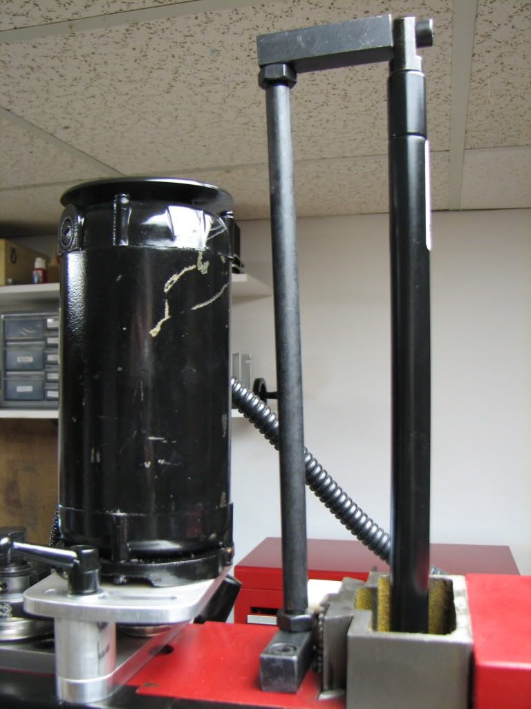
Looks worse in 'real life' than in the picture.
[EDIT: Hold comment until I get a chance to look at this closer. I think there's a part from the torsion spring assembly in the way that needs to be removed first.
My biggest concern follows...]
[EDIT: Woke up in the middle night calling myself an idiot. (Not unusual.) I realized the lack of lower Z was due to the same problem. I needed to remove the torsion spring.]
g) Sure seems like I lost a couple of inches down below. Not that I'm unused to that...but I didn't expect it here...
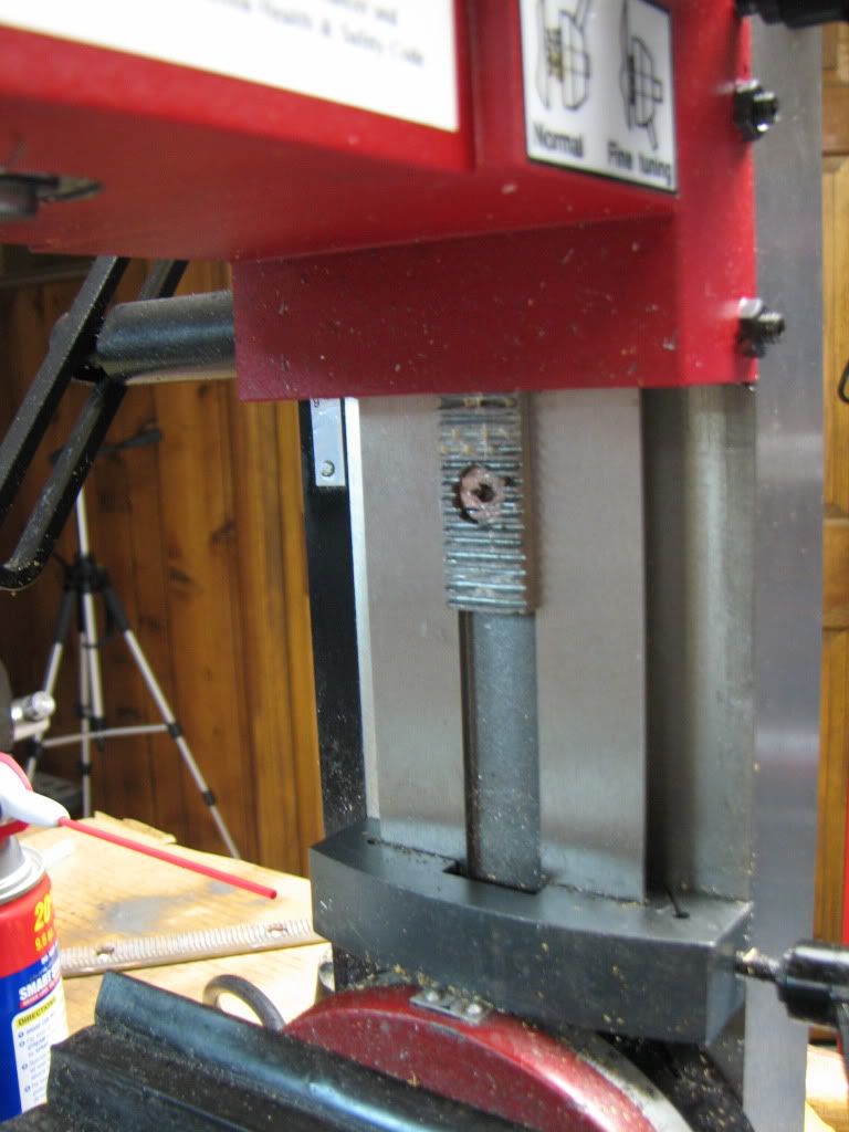
That seems to be a function of where the hole is drilled in the back of the column and where the spring rod is attached.
So that's the bit I'm wondering if I did right...
Anybody else who's done this see that?
You would think it could go another 4" but if you do, then there won't be enough spring rod at the top end. Maybe 2"? In other words...instructions say to put the hole at 12" from top...what did you guys do?
For all that...you get maybe 2" at the top...but if that's at the loss of the bottom...I'm not so sure this is worth it.
Let me know if you'd rather I post elsewhere...
Took a run at making the Z extension mod on the X2 today. Overall it went well but I wanted to post a couple of observations and I'm wondering if I did something wrong...
First the observations...
a) The template they (LMS) give you to drill the two holes at the top is not to scale. Measure instead.
b) It was not clear to me where center was. Center of the column? Or center of the dovetail. I used the dovetail but I don't think it matters other than you should use the same reference for the hole on the back of the column. But even that's not critical.
c) The instructions don't explicity say (at least I didn't see it)...but remove the motor.
d) When you loosen the rack and/or insert the new one...you will see the handles of the head turn as you push or pull the rack.
e) The Z stop is the last thing to attach. Also, at some point they talk about moving the head all the way up...if you do, you'll run off the old rack and it can be difficult to get it back on.
f) I believe the X distance given for placing the support on top of the head is too short. When all is said and done, the two shafts do not appear parallel to me.
Looks worse in 'real life' than in the picture.
[EDIT: Hold comment until I get a chance to look at this closer. I think there's a part from the torsion spring assembly in the way that needs to be removed first.
My biggest concern follows...]
[EDIT: Woke up in the middle night calling myself an idiot. (Not unusual.) I realized the lack of lower Z was due to the same problem. I needed to remove the torsion spring.]
g) Sure seems like I lost a couple of inches down below. Not that I'm unused to that...but I didn't expect it here...
That seems to be a function of where the hole is drilled in the back of the column and where the spring rod is attached.
So that's the bit I'm wondering if I did right...
Anybody else who's done this see that?
You would think it could go another 4" but if you do, then there won't be enough spring rod at the top end. Maybe 2"? In other words...instructions say to put the hole at 12" from top...what did you guys do?
For all that...you get maybe 2" at the top...but if that's at the loss of the bottom...I'm not so sure this is worth it.
") )
)


