You are using an out of date browser. It may not display this or other websites correctly.
You should upgrade or use an alternative browser.
You should upgrade or use an alternative browser.
Westbury side paddle
- Thread starter Herbiev
- Start date

Help Support Home Model Engine Machinist Forum:
This site may earn a commission from merchant affiliate
links, including eBay, Amazon, and others.
Herbiev
Well-Known Member
- Joined
- Jan 6, 2011
- Messages
- 2,360
- Reaction score
- 310
Gerhardvienna
Gerhardvienna
You shock me! If that `s "not a lot", what is???http://s1237.photobucket.com/user/H...B-45F0-BC94-67ED18C4E1AB_zpswxwvliky.jpg.html
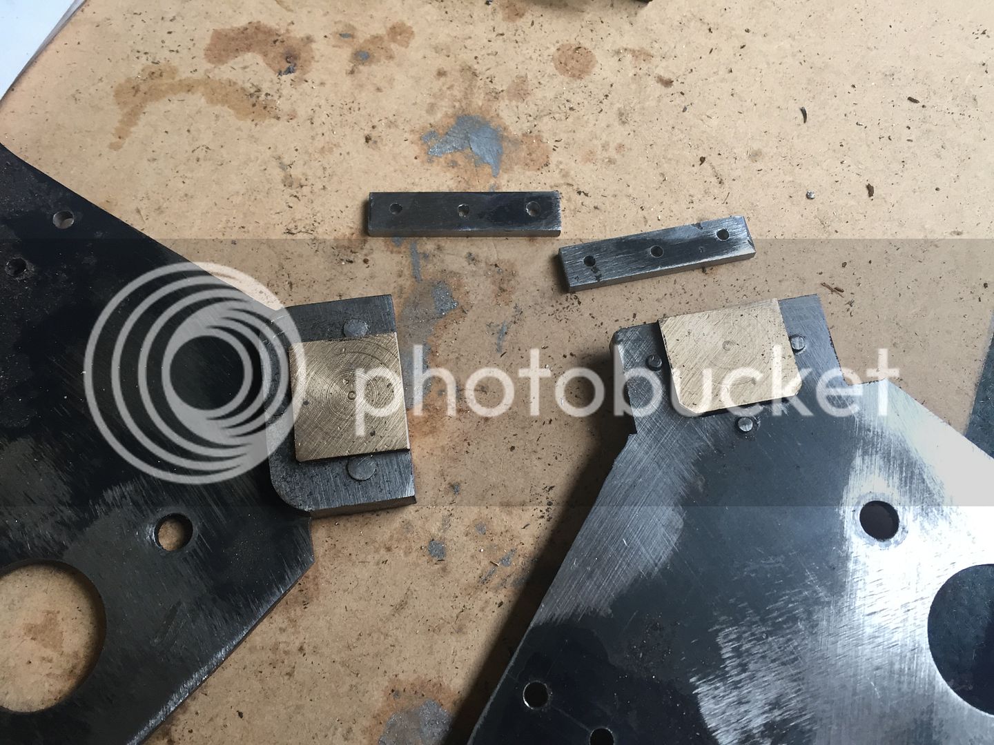
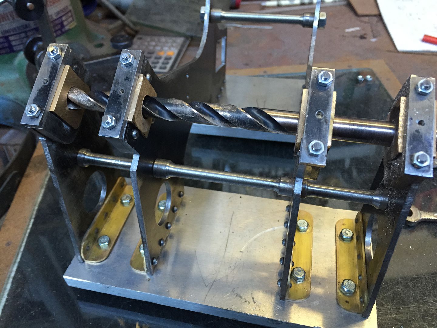
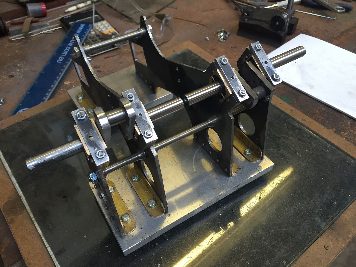
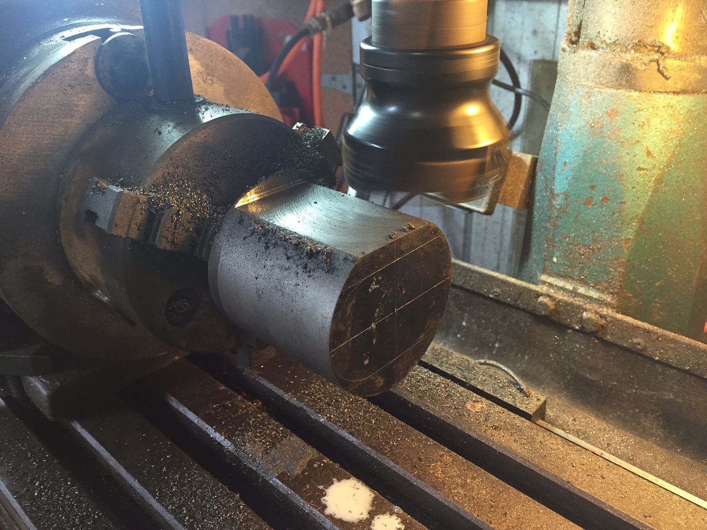
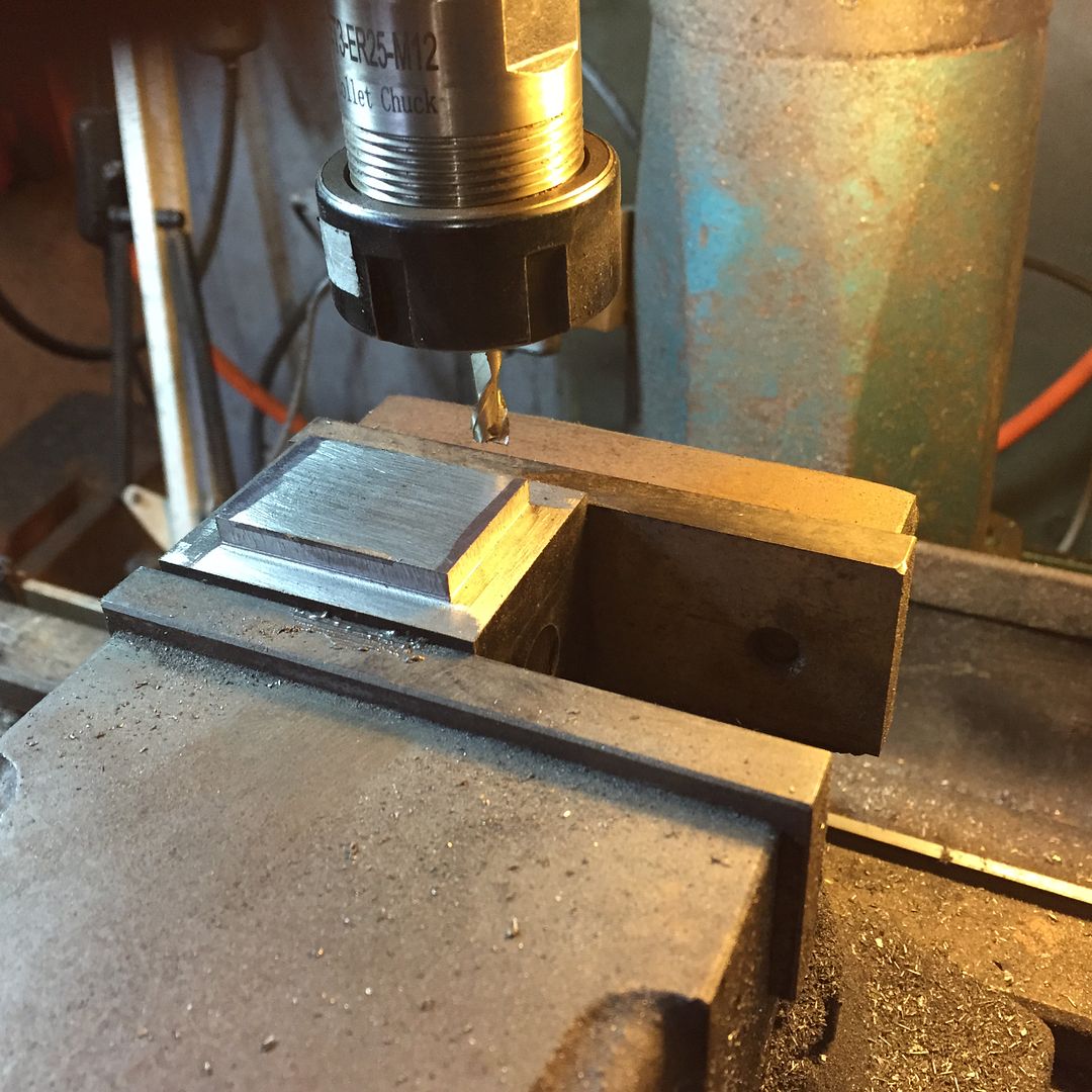
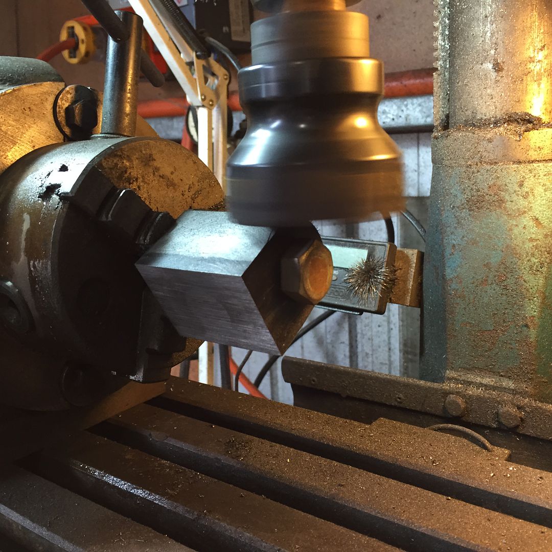
Not a lot of progress ............................
Looking forward to your next steps!
Regards
Gerhard
- Joined
- Jun 4, 2008
- Messages
- 3,285
- Reaction score
- 630
I made built-up cranks. Decide whether you are going to build the water pump. If not, then the inner shafts of the crank can be made longer to just fit a simple coupling.
- Joined
- Nov 14, 2009
- Messages
- 675
- Reaction score
- 104
Yep,it was built up shafts for me,much easier
Don
Don
- Joined
- Nov 14, 2009
- Messages
- 675
- Reaction score
- 104
You dont hang about do you,looking good
Don
Don
- Joined
- Jun 4, 2008
- Messages
- 3,285
- Reaction score
- 630
Just the converse here. Too hot to be outdoors.
Gerhardvienna
Gerhardvienna
Hi Herbie
Thats fast!
While I`m waiting for my materials, you make the chips fly:fan:
Regards
Gerhard
Thats fast!
While I`m waiting for my materials, you make the chips fly:fan:
Regards
Gerhard
- Joined
- Jun 4, 2008
- Messages
- 3,285
- Reaction score
- 630
You'll notice that the cylinder cover is drawn rotated 90 degrees. The flats on the flange are shown horizontal while they are vertical when mounted (they are the mount points for the crosshead guide bars).
Notice the mounting holes by the flats need to be countersunk to avoid conflict with the guide bars. If you rotate the hole pattern 15 degrees you avoid that conflict and can use the same screws all around. Of course you'd need to rotate the holes on the cylinder to match.
Notice the mounting holes by the flats need to be countersunk to avoid conflict with the guide bars. If you rotate the hole pattern 15 degrees you avoid that conflict and can use the same screws all around. Of course you'd need to rotate the holes on the cylinder to match.
Gerhardvienna
Gerhardvienna
If you rotate the hole pattern 15 degrees .................................
Hi kvom
Could you please show this "for dummies" (ME!!) on a drawing? This will help me, when I find some time to build that engine..........:hDe:
Regards
Gerhard
- Joined
- Jun 4, 2008
- Messages
- 3,285
- Reaction score
- 630
WRT to rotating the mounting holes, it's advisable to draw the cover in CAD and see if there is interference with the size of fastener you plan to use. Metric, imperial, and BA screw heads all have different sizes.
Gerhardvienna
Gerhardvienna
- Joined
- Jun 4, 2008
- Messages
- 3,285
- Reaction score
- 630
Actually it's best to ignore that advice. I was going by memory, but today I went to look at my partial build, and doing the holes that was will not fit as the screw heads or bolts will interfere with the bars. I had decided to just use the 6 holes on the sides (45 degrees apart) and skip the top and bottom ones. I used 5-40 screws, and the head of a flat head capscrew is .28" in diameter, so too large. Even 4-40 is too large unless you trim the head.
Gerhardvienna
Gerhardvienna
Trimming the heads was what I was thinking about. As far as I`m not building this engine at the time, I`m just "collecting" the tips and hints to avoid mistakes:hDe: Thanks for advice!
Regards
Gerhard
PS.:In my post #2/page 1 in this thread I forgot the last PDF-File, Side 14! It is placed now in the named post, just some finishing notes, no drawings. SORRY!!!!!!!!!!!!!!!!!!!!!!!!!!
Regards
Gerhard
PS.:In my post #2/page 1 in this thread I forgot the last PDF-File, Side 14! It is placed now in the named post, just some finishing notes, no drawings. SORRY!!!!!!!!!!!!!!!!!!!!!!!!!!
Last edited:
Similar threads
- Replies
- 13
- Views
- 1K
- Replies
- 25
- Views
- 3K
- Replies
- 0
- Views
- 245


