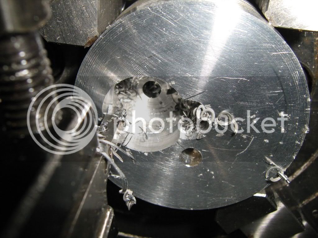
I started to build this engine when it was published in Model engineer magazine in the 80's. I am now going to try and carry on where I left off. I have to work on a tight budget but have ordered the three gears it needs. I managed to find in my box of aluminium the piece for the timing case so thought I would make a start only to discover the first operation is to drill and ream a 5/32" hole and I dont have a reamer that size. I got a shock when I found prices around £16 for one. I have read about making D shaped reamers but can't decide if it would be more trouble than it was worth.
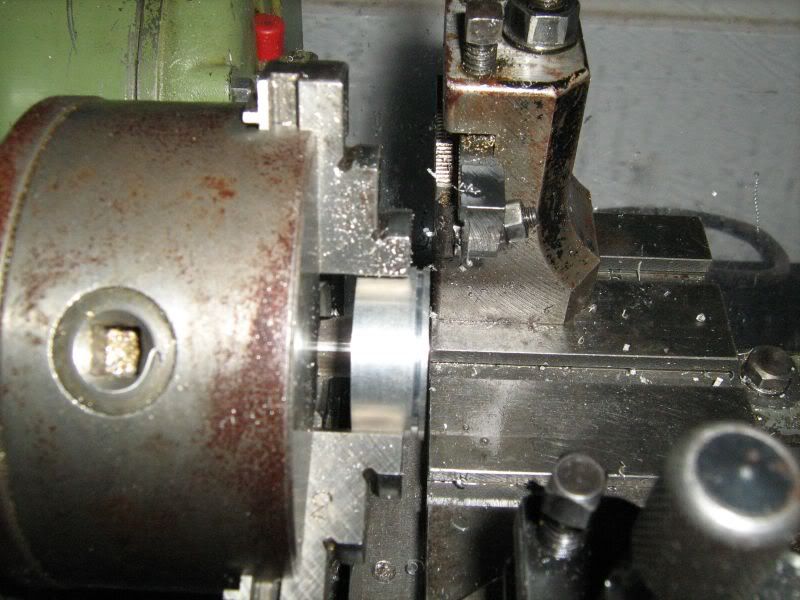
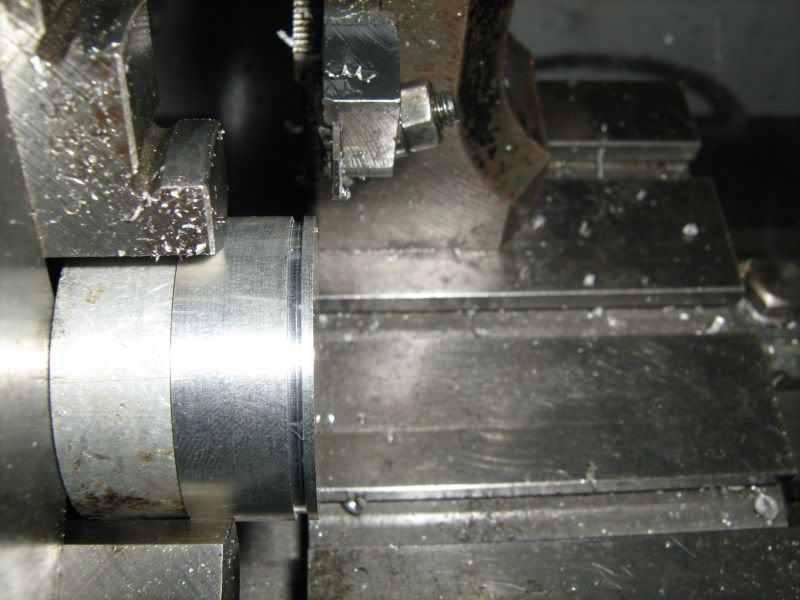
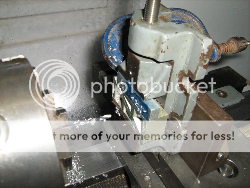
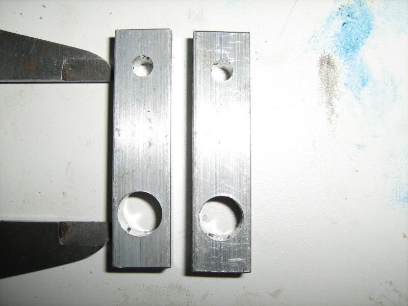
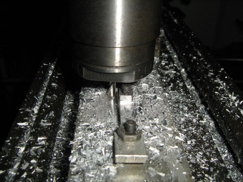
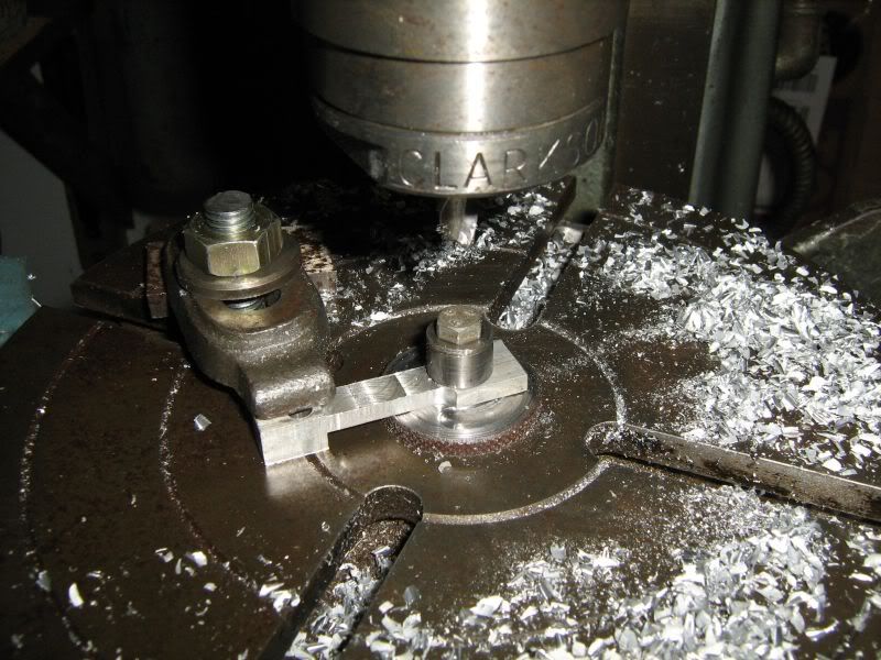
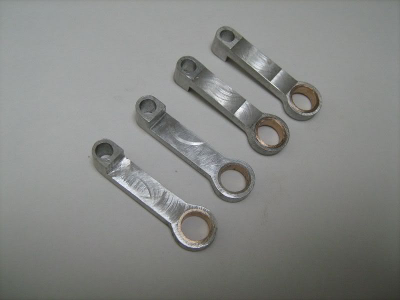
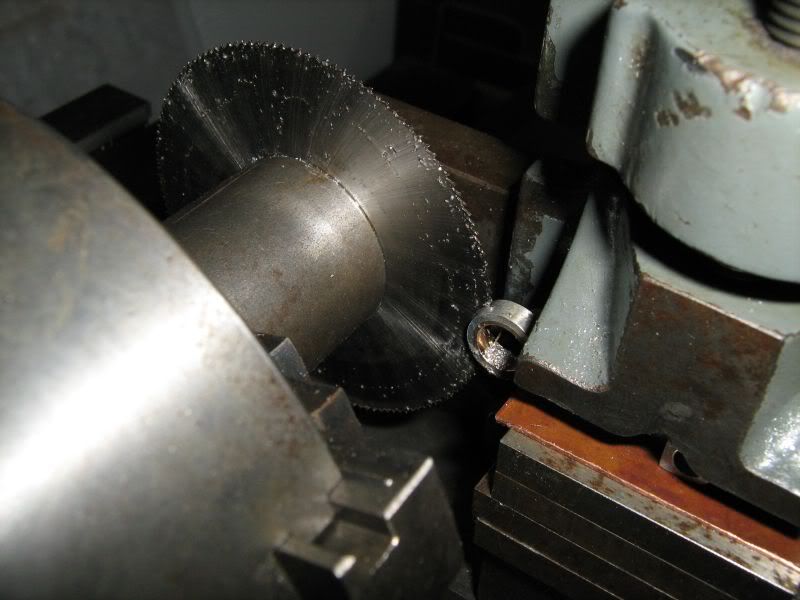
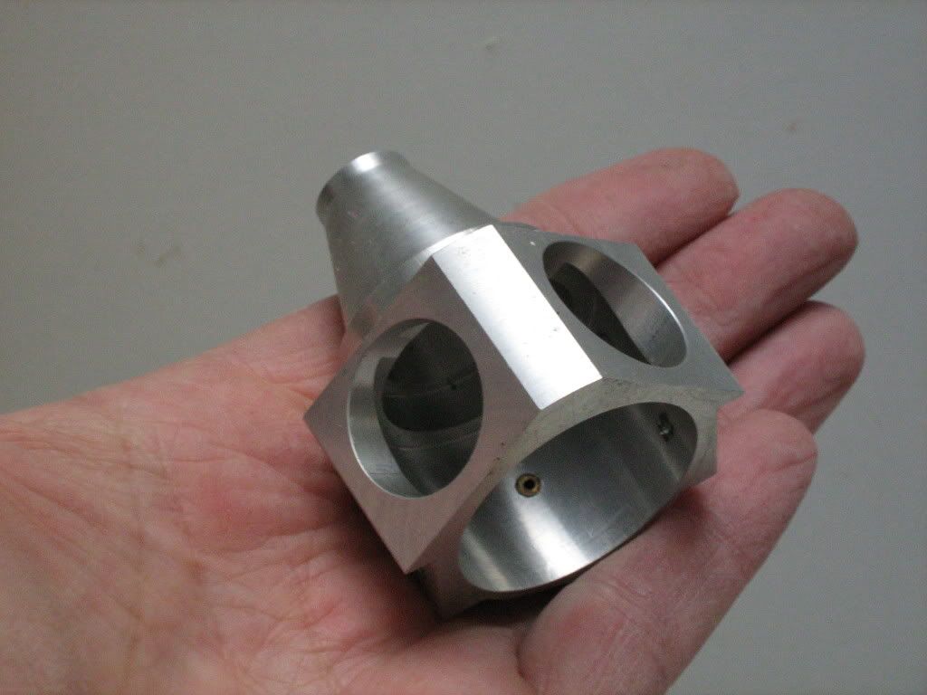
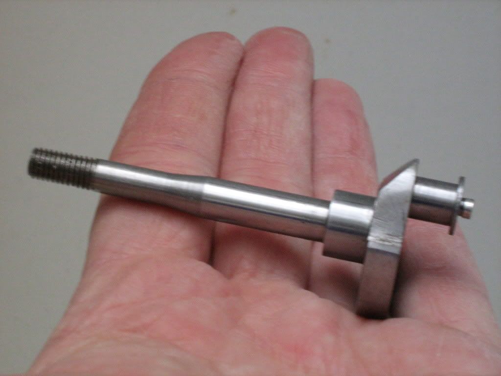
Anyway here are the photo's of work so far.
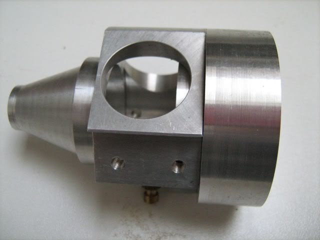
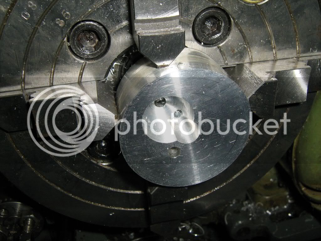
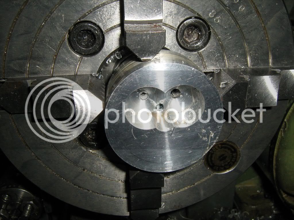
Crankcase
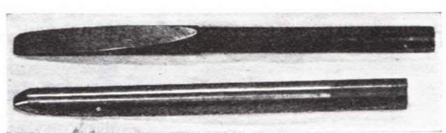
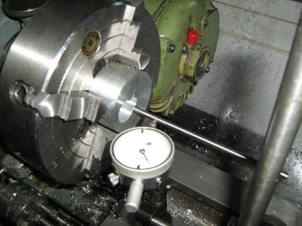
crankshaft
Anyone here built one?
Mo.
Anyway here are the photo's of work so far.
Crankcase
crankshaft
Anyone here built one?
Mo.