Using a rotary table

Home Model Engine Machinist Forum

Help Support Home Model Engine Machinist Forum:

This site may earn a commission from merchant affiliate links, including eBay, Amazon, and others.

steamboat willie

Well-Known Member
Joined
Jun 2, 2012
Messages
67
Reaction score
7
Hello!
I find it easier to ask silly questions rather than making stupid (and expensive) mistakes, so here goes:
I have recently acquired a Vertex 6" rotary table to use under a small milling machine and while much of its operation is intuitive I would like to be able to read up on how to use it properly before any damage is done.
Can any member of this august body direct me to a treatise on how to properly use a rotary table, incliding clamping the job, setting out radiis etc. I know it is all pretty basic stuff, but I want to advance the sophistication of my mistakes...:D
Many thanks!
Steamboat Willie
 
Mr. Steamboat,

If you're new to rotary tables, I know of a good DVD
on the subject. I don't wish to 'commercialize' this
site, so if you wish you can contact me off-site.

The DVD is aimed at newbies, and covers setup, calculations,
fixtures, dividing plates and a lot more stuff.

Hope this helps,

Lex
 
Hi Chucketn!
many thanks for the web addresses relating to the rotary table. I was aware of much presented in these sites but was more after information on safe clamping methods, and setup of the mill/rotary table. For example I have to make two (for want of a better description) tombstone shaped supports for a small steam engine (read make replacements for yet something else broken in transit - must have been Football Day down at the mail exchange when my parcel went through). I was thinking of mounting the brass (5mm thick) on top of a piece of perspex and allowing the cutter to penetrate the perspex to ensure adequate depth of cut. Is that an acceptable practice? Also, is there any specific way in which the workpiece is to be secured to the work table of the rotary table?
I will now return and reread the links to which you so kindly referred me.
many thanks!
Cheerio!
Steamboat Willie (aka Bill)
Canberra, Australia
 
Hi Willie,
Like you I made same mistakes.
Was a miracle,my first three jobs went thru unscathe.Subsequent jobs were castrophic.
Made my own 3" Rotary Table with a bought out Japanese worm & wheel which cost me S$48 while imported "Branded but made in China would cost me S$300.My DIY Table ,gear set and material came up to S$58.See fotos.Latest job was a serrated propeller drive washer.Made a mistake dividing by hand wheel count.Went to the scrap bin.The next piece was OK.

The last foto shows the steam engine with speed governor and weights which require the use of rotary table to turn the sphereical parts.Free hand machining would very odd looking brass balls.


Gus from faraway Singapore.

IMG_0424.jpg


IMG_0583.jpg


IMG_0440.jpg
 
Hello Gus!
Thanks for your reply! That's one fancy looking engine there! Its one thing to build an engine, but something else quite again when you make the equipment that you then use to build your engine. I dips me lid good sir to a job beautifully done.
Thanks for your comments. I am pretty sure I know what I have to do but just lack the confidence and experience to venture forth lest I bugger up something irrepairably, meaning the rotary table of course. I have been told that that is something that is pretty hard to do if you take care, but they also said that the Titanic wouldn't sink too...
I shall continue on...
Cheers!
Steamboat Willie.
 
I also have a 6" Vertex and am well pleased with it.

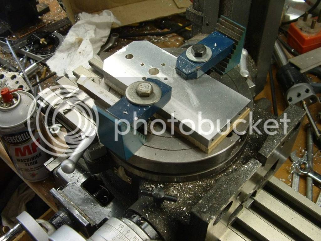
Typical flat clamping with "T" nuts and stepped clamps etc - the use of scrap under the job is mandatory when cutting all the way (don't ever try to work a fraction away from the RT face) - my favourite packing material is 6mm MDF. Use Aluminium or other uniform thickness scrap for accurate work.

If you have to work all around a job then you must use 3 or 4 clamps and remove and replace as required to dodge the cutter path. On some jobs you can preplan where the voids are going to be to provide intermediate "tooling holes" for bolting to the RT - these will be further machined away later.

When doing round jobs use the central MT3 hole and a drawbolt - I often turn up sacrificial MT3 stubs in Aluminium to suit the bore of the job. When you are after dead nuts accuracy then rather clock it.

When holding with only a single central drawbolt be careful that the cutter forces do not rotate the work - particularly in the direction that will loosen the bolt - avoid climb milling other than light final finishing cuts.
Use multiple securing points wherever possible.

When performing angular operations try to start at datum zero (or 90 / whatever whole number) far less chance of making maths errors - sometimes this is not an option and you are forced to clock and use whatever datum value you get - be careful with the maths - check and double check - it is just too damn easy to make a hash of it - especially when changing direction - plan all your angular values in advance and check them. Write it down - don't rely on memory.

Ken
 
Steamboat---I find that 99% of the things I do with a rotary table demand that the parts I'm working on must be held in a chuck. So---I made an adapter plate and mounted a 4" three jaw chuck on my 6" rotary table. It involved a bit of frustration to get the chuck mounted exactly in the center, with zero measurable run out, but I did. The only time I get into trouble is having to ream something held in the chuck. My mill runs out of headroom, but I have shortened a couple of reamers to suit my set up and it works fine.---Brian
 
When performing angular operations try to start at datum zero (or 90 / whatever whole number) far less chance of making maths errors
Ken

Whenever I need to mill an arc on the RT I draw two lines at start and end positions with a permanent marker on the face of the table, less chance to go over the limits.

Roberto
 
If you don't want / can't use a "sacrifical" plate under the workpiece for some reason, you can start with a blank a little thicker (say 1 mm), do your job on the RT until you are 0.75 mm above the table, then flip over the piece in the vise and mill away the last slice.
 
Sacrifical plates are great, either aluminium or steel. Using them allows you to put in tapped clamping holes where you like. Great for clamping odd shaped parts.

Paul.
 
Brian, Roberto and Ken,
Thankyou all for your advice and assistance. It is these pragmatic bits of wisdom that are exactly the sort of thing that I need. I hadn't thought of using MDF as a base, but on reflection it is manufactured to a very exacting tolerance and is an ideal flat surface. I have always been aware that the glue in MDF is extremely hard on tool edges, notably saws, and plane and chisel edges. I would imagine that the small amount of contact a milling cutter would have with MDF should pose no trouble at all. Thankyou for that tip, and the tip of using a plate of aluminium as well.
I have for many years kept a pad and pencil next to my lathe - its indeed comforting to read that others do it too, because I thought it was just me and an idiocyncratic a sign of the early onset of dementia! It is indeed comforting to know that others do it too!
So, many thanks for your postings kind sirs! Your advice is most welcome.
Cheerio!
Steamboat Willie
PS Roberto - I like your beam engine picture on your name plate! Any chance of an extra photo or two?
 
Thanks also Paul for that advice - to use a steel plate not only as a sacrificial plate but also as a mounting plate.
Just the sort of practical advice I was after!
Steamboat Willie.
 
Following on from Brian's comments - I also have an adaptor plate which can hold my lathe's 3 & 4 jaw chucks - this is convenient in that I can take the work directly from one to the other.
Mine does not have an exact location (clearance holes) and has to be clocked.

rtmtg1.jpg

rtmtg2.jpg


rtmtg3.jpg


rtmtg4.jpg


Regards,

Ken
 
Hi Willie

MDF is good for sacrifical plates but tends to expand rapidly if it came in contact with water, oil or other liquid substances, so you need to avoid cutting fluid.

This is a pic of my wood beam engine with a better resolution (sorry for the quality, but this is the best I can do with my cheap digital camera). You can find the plans here (#1 on the list):

http://www.john-tom.com/html/ElmersEngines.html

Roberto

wood_beam.jpg
 
I too put a 3-jaw chuck on my rotab, but one with 2-piece jaws. With aluminum soft jaws in place, I mill a pocket for the diameter I need, and then can accurately remove and replace the work.
 
Ken I,
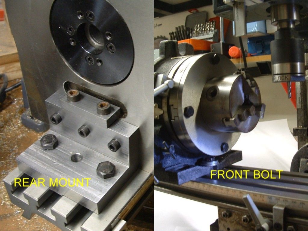
Many thanks for the trouble that you have taken to photograph and post the method of mounting a rotary table onto a milling machine bed. Your photos have answered most of my queries. One query still remains, and it is this: The rear register on the back face of the rotary table (the 'T' shaped slot) is essential to the effective mounting of the table on the mill. Why then is the depth of this indent only about 2mm? I know that it just has to hold it there, but 2mm seems very little to support the downward force to secure the mill to the table given the loads that it must handle against cutters and the like. It obviously works, but why so little purchase? Also, in your first photo you show three horizontal umbrako bolts in the vertical face of the mounting bracket. What do these do/screw into please?
Many thanks again for your time and trouble - it has helped me enormously!
Cheerio!
Steamboat Willie.
 
Prof65, that is lovely. How about starting a build thread for it? I am absolutely enthralled by beam engines.
 
Steamboat - 2mm may not seem like much but it would literally require tonnes to break it out and its only for location.

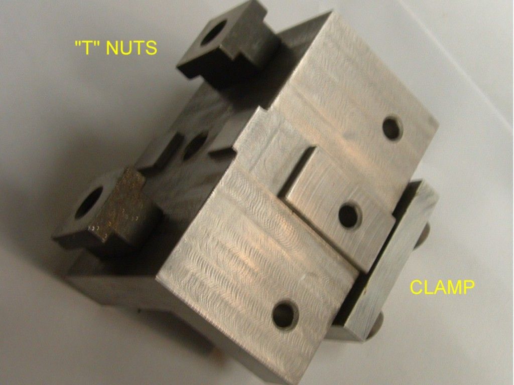
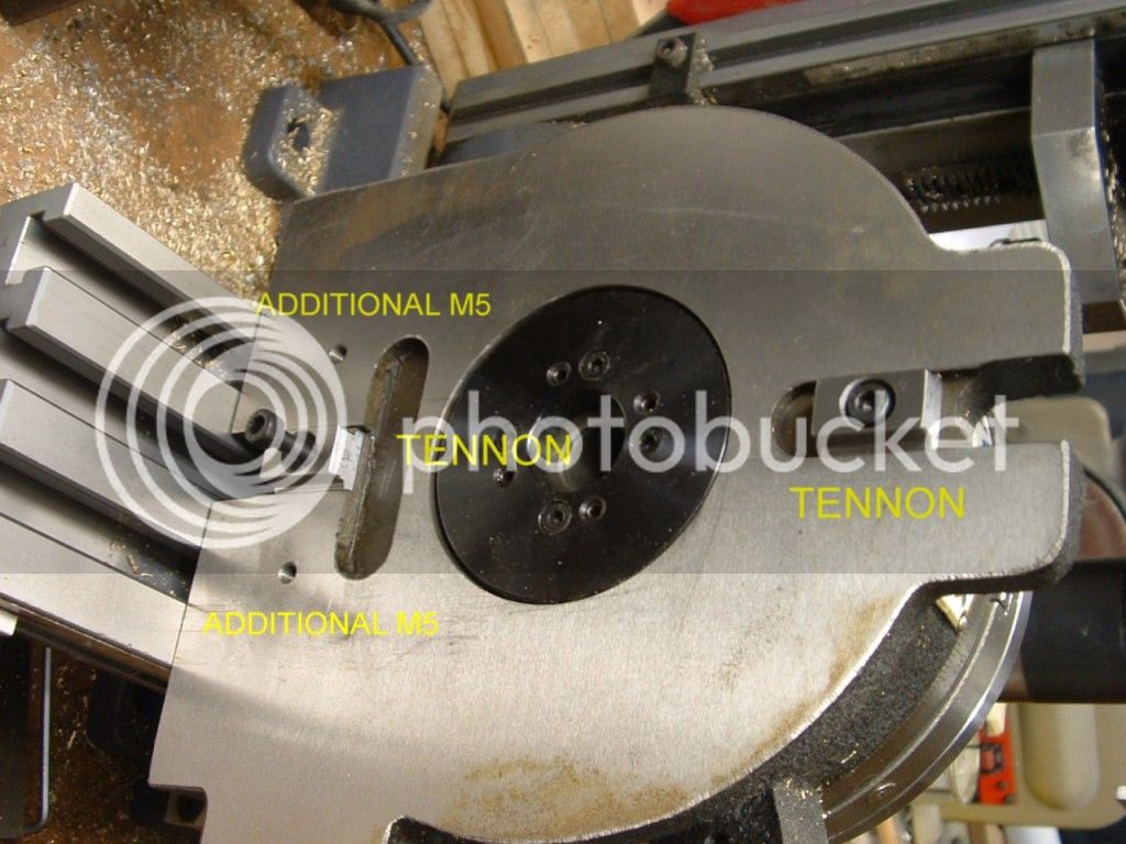
The bracket I made was because the "T" slots in my minimill wouldn't work for the RT axis horizontal - the centre bolt goes into an existing M5 in the Vertex head - I drilled and tapped an additional two holes - maybe one would be enough but I prefered more.

I also made the tennons - the adaptor bracket acts as a squaring tennon as well. This allows me to slap it on the table and not have to bother clocking.

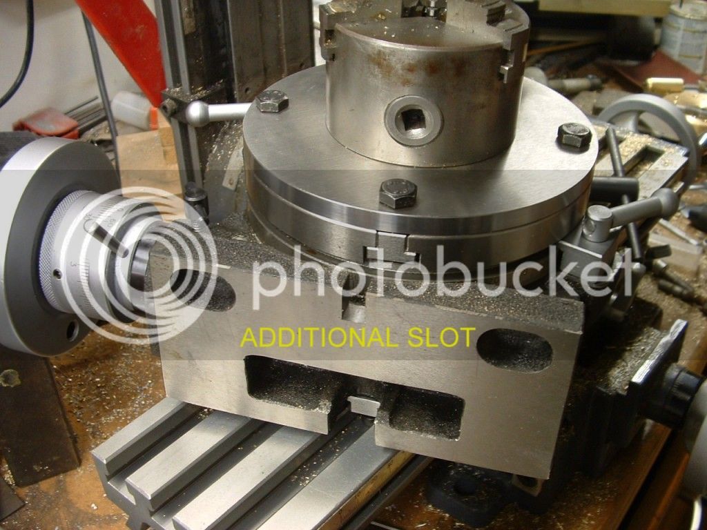
Just for reference I also milled the slot in the front for the foward clamp and also added two M8 holes which allows me to use the RT as a right angle plate when its flat on its back.

The photos are from previous posts that have vanished.

Here's a couple more :-

eb6rtflat.jpg

Some worked clamped on an MDF backing.

eb6mtend.jpg

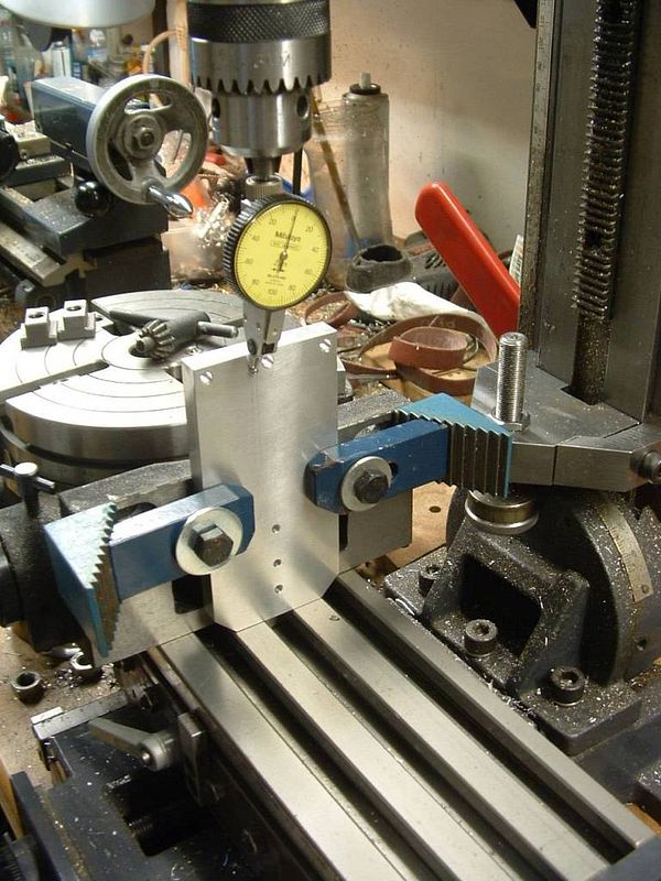
Using the butt end as a right angle plate (didn't have one at the time).

Regards,
Ken
 

Latest posts

Back
Top