Twin D/A Oscillator.

Home Model Engine Machinist Forum

Help Support Home Model Engine Machinist Forum:

This site may earn a commission from merchant affiliate links, including eBay, Amazon, and others.

dvbydt

Well-Known Member
Joined
Oct 27, 2010
Messages
114
Reaction score
4
I had better get my first build log on this forum down on paper or it will end up in finished projects! The inspiration was this advert on the Internet :-

http://www.prestonservices.co.uk/stationary.htm

A great looking engine but not one I copy.

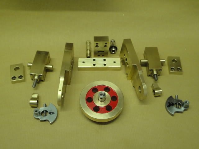
With a 12 ins flywheel, it was too big to do full size and I have no casting facilities. Searching on the Internet, Elmer did both horizontal and a vertical oscillators, but of course, I had to do one my way! Looking at what I had for materials, the flywheel had to be made from a 2.5 ins diameter blank and the body from 2 x ½ ins stock. (In the UK some bar stock is still sold in Imperial sizes.) The throw on the crank was to be 10 mm, so with a stroke of 20 mm, 16 mm seemed about right for the bore.

Using these sizes, I sketched out the rough design :-

TOjpg.jpg


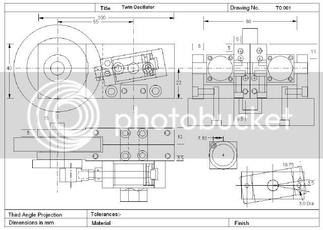
This is just a first draught and I am constantly changing it as I make this build.

Ian
 
Started on the cylinders using round stock and made a plug gauge to 16.00/16.05 mm.
Faced to length and bored out to plug gauge size.

CylinderBlanks.jpg


Roughed milled the blanks and finished with a flycutter.

Flycutting.jpg


Started on the pivots.

Roughing.jpg


Note the centre drill.

Ian
 
With a tool mounted in my boring head, I then turned the pivot oversize.

Pivot.jpg


Then it could be mounted in the collet chuck on my lathe.

TurningPivot.jpg


Finished the turning.

Cylinders.jpg


Beginning to look interesting!

Ian
 
Thats a neat way of producing a cylinder for holding in the chuck - never thought of doing that before.

The only thing wrong with watching a thread from the beginning is that it takes sooo long. More please :D
 
Thats an interesting design Ian, and I like your use of the boring head.

Keep them comming

Stew
 
Thanks for taking an interest. See photo further down where I use the mill to turn the crank pin.

Tapped.jpg


Cutting the "O" ring groove in the end plate whilst it was still in bar form.

Oringgroove.jpg


End plates were then milled square but the edge with the port in, was left 0.25 mm proud.
Then they were drilled.

EndCapDrilling-1.jpg


Ian
 
The cranks were roughed out in a 4 jaw on the lathe.

CrankBlank.jpg


Then the centre was drilled and reamed on the same set-up as the crank pins were turned with the boring head, so as to get them in line.

CrankPin.jpg


Mounted in a brass jig and milled.

MillingCrank.jpg


Ian
 
More build photos.

CrankPinJournal.jpg


The Body Plates have been machined to size and clamped together, they are drilled and reamed.

BodyPlates.jpg


More milling and then the Air passages are drilled.

AirPassages.jpg


Ian
 
The piston rods are stainless steel so they were screwcut M5 then cleaned up with an M5 Die.

ScrewcuttingM5.jpg


The inlet/exhaust manifold has to be bolted onto the main plates so two "O" ring recesses were cut with a 6mm slot drill. No side load on the drill chuck, so this is OK.

ORingMilling.jpg


This is the piston, rod and end plate assembly.

PistonAssembly.jpg


Ian
 
Now I have reached the assembly stage (on a temporary base).

FirstAssembly.jpg


Does it run? Yes it does but leaks air due to my drilling error, easy to fix. Does it rev? Yes but it is a bit unbalanced and vibrates on the table. Since the cranks are at 90 degrees, to enable self starting and four pulses per rev, it was to be expected. I am going to remove some weight from the crank pin area anyway. The "O" rings on the piston cause some stiction, so, instead of 20% ring squeeze, by deepening the groove, I have reduced this to 10%.

Started on a proper base.

FlywheelClearance.jpg


And cleaned off machining marks.

AlltheBits.jpg


Next photo is just a tease.

Ian
 
Ian,
Very nice and very quick, I'm still thinking about the drawing.

A very nice model.

Dave
 
Dave, not really that quick. I had it built to the first assembly stage before I asked the Moderator if it might be of interest. The confidence shown by the experts on here who can start a log with the first bit of swarf, is really impressive.

This is the completed engine.

View3.jpg


And as promised, the video.

<iframe title="YouTube video player" width="480" height="390" src="http://www.youtube.com/embed/AlaB3aKpenc" frameborder="0" allowfullscreen></iframe>

Slow speed is about 250 rpm and fast 2,300 rpm.

There are still a few minor things to do. Crankshaft bearings will be replaced with ball races,
the taper pins finally fitted and a perspex cover to keep the dust out.

The next build will be a V8 air motor. (But I may be some time).

Ian
 
Fitting two ballraces has made the motor run very smoothly. A bit of work on the port faces eliminated most of the air leaks so it will now run at about 100 rpm at 10 psi. Working with Perspex is not my favorite job and it took some time to get this dust cover finished, but there it is on display, at last :)

Ian

Display.jpg
 

Latest posts

Back
Top