


Hi Everyone
I have been in the shop for a new thing:
You may remember that i had presented a micro-turbine more than two years ago...
However, I have built another turbine with a 20 mm turbine wheel.
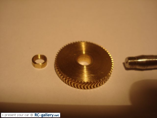
The Wheel with the locking nut and part of the shaft (with a cone on it to carry the turbine wheel)
When i was running the turbine for the first time, i really got scared by the sound it was making. There was an imbalance and the sound was absolutely terrible!
Well, i immediately tried to balance it. First attempt was to use two razor-blades locked in the vise with a distance piece between them. Then i have put the turbine with the shaft on the two blades. But it dit not work so well...
Though i could run the turbine now. But i was not very pleased by the sound and the bearings would run rough after only a few times running running it...
I then was thinking about another method of balancing it and all the time thought about doing it with magnets in a Way that the turbine wheel is completely suspended in air because of the magnets. But i never realized it and after a while i forgot about the turbine.
Independet to this, one day i crossed air bearings on the internet. And also forgot about them...
Well and last week i had a flash of genius and decided to build an air bearing balancing tool for my turbine wheel:
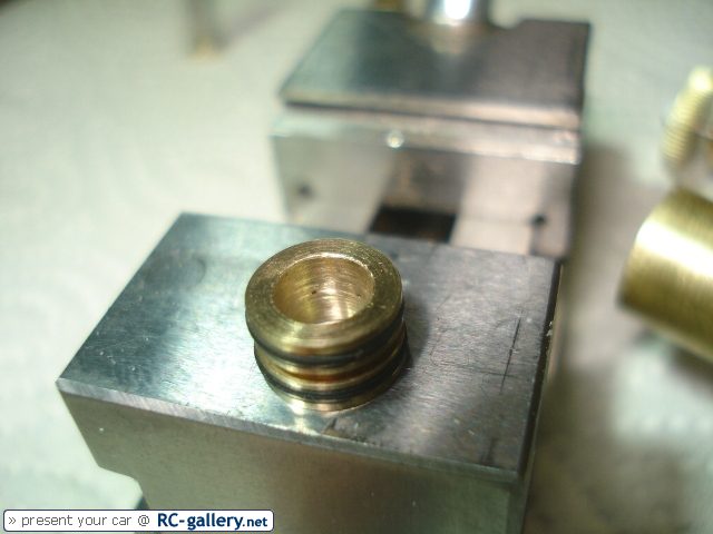
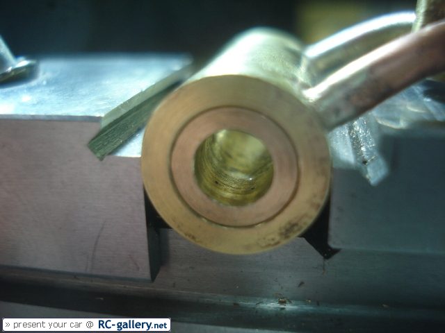
The air bearing consists of two sleeves with six small holes in a circumferential array. The holes have 0.3 mm diameter...
The Sleeve has 5mm bore and 8mm outer diameter and the groove in the middle brings the air to all of the six holes. The two o-rings seal the groove to the side...
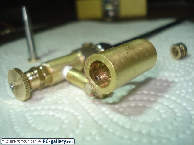
Here you can see the bearing block with the air supply hole. (In the background the air control valve)
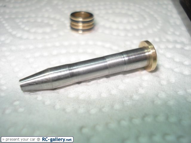
The shaft... (turned between centres...!) The cone will hold the turbine wheel and next to the cone and the brass disc you can see the bearing surface on the shaft.
The brass disc works as an axial bearing to prevent the shaft from moving out of the sleeves. The clearance between shaft and sleeve is in about 0.01 mm; Shaft has 4.95 mm diameter and the sleeves have ben reamed with a 4.97mm reamer.
Sleeves in the bearing block...
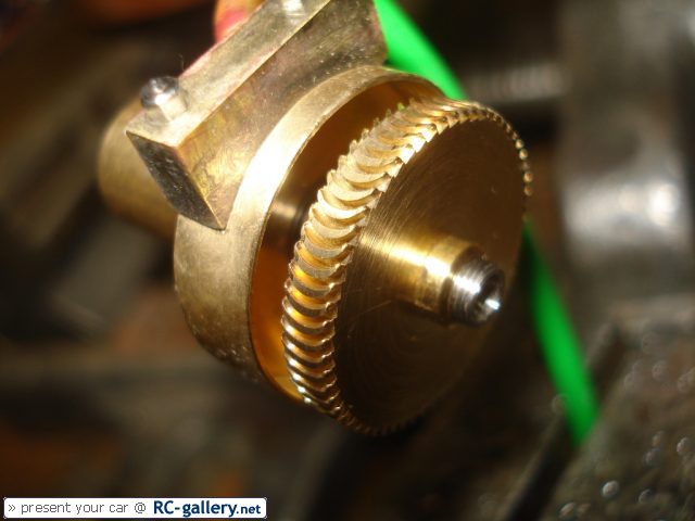
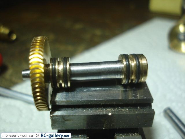
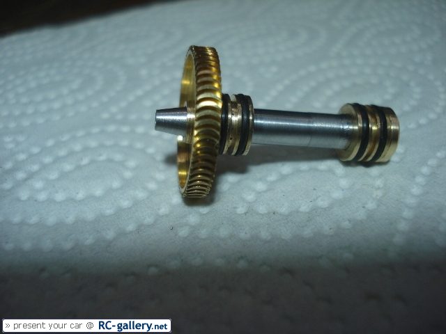
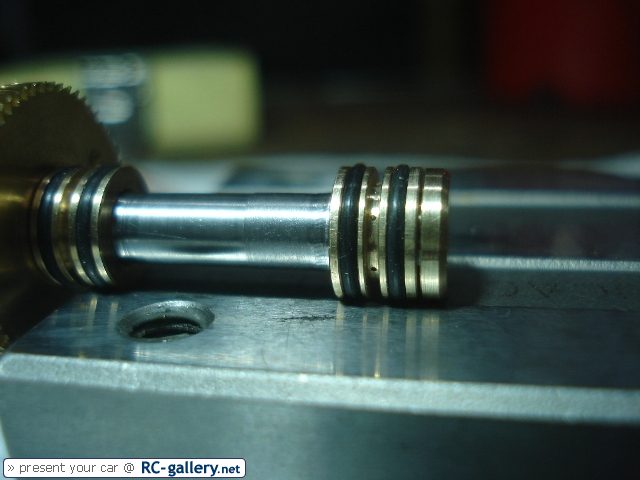
And some pictures of the turbine wheel together with the shaft and the sleeves:
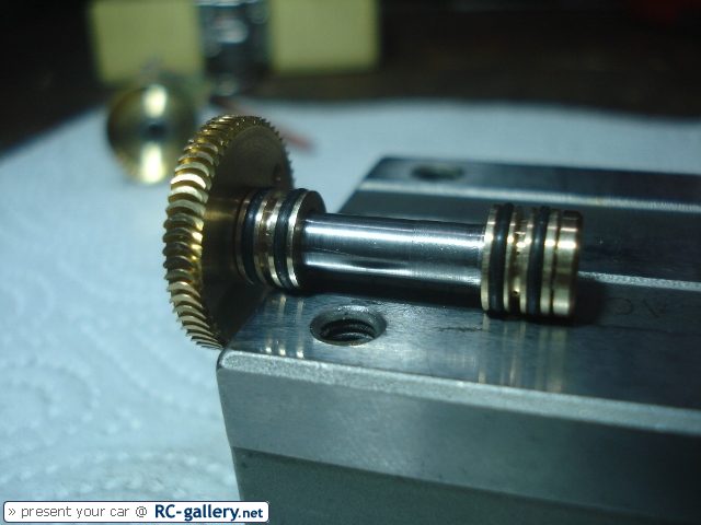
Again easy to see: the 0.3mm holes in the sleeve...
Cheers Florian
I have been in the shop for a new thing:
You may remember that i had presented a micro-turbine more than two years ago...
However, I have built another turbine with a 20 mm turbine wheel.
The Wheel with the locking nut and part of the shaft (with a cone on it to carry the turbine wheel)
When i was running the turbine for the first time, i really got scared by the sound it was making. There was an imbalance and the sound was absolutely terrible!
Well, i immediately tried to balance it. First attempt was to use two razor-blades locked in the vise with a distance piece between them. Then i have put the turbine with the shaft on the two blades. But it dit not work so well...
Though i could run the turbine now. But i was not very pleased by the sound and the bearings would run rough after only a few times running running it...
I then was thinking about another method of balancing it and all the time thought about doing it with magnets in a Way that the turbine wheel is completely suspended in air because of the magnets. But i never realized it and after a while i forgot about the turbine.
Independet to this, one day i crossed air bearings on the internet. And also forgot about them...
Well and last week i had a flash of genius and decided to build an air bearing balancing tool for my turbine wheel:
The air bearing consists of two sleeves with six small holes in a circumferential array. The holes have 0.3 mm diameter...
The Sleeve has 5mm bore and 8mm outer diameter and the groove in the middle brings the air to all of the six holes. The two o-rings seal the groove to the side...
Here you can see the bearing block with the air supply hole. (In the background the air control valve)
The shaft... (turned between centres...!) The cone will hold the turbine wheel and next to the cone and the brass disc you can see the bearing surface on the shaft.
The brass disc works as an axial bearing to prevent the shaft from moving out of the sleeves. The clearance between shaft and sleeve is in about 0.01 mm; Shaft has 4.95 mm diameter and the sleeves have ben reamed with a 4.97mm reamer.
Sleeves in the bearing block...
And some pictures of the turbine wheel together with the shaft and the sleeves:
Again easy to see: the 0.3mm holes in the sleeve...
Cheers Florian
 (Total sucess Thm: )