I never use inserts so I know almost nothing about them. I looked at the pictures of the inserts in the last link and what I see are flat top inserts with chip breakers. They have to be flat top when they can be used either right or left hand and can be rotated to three different positions, so no back rake is possible.
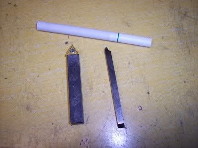
Your quote earlier that the slope on the insert was built in would make me think that the insert would be thinner on one side than the other and that should be noticeable on the picture of the insert with two adjacent cutters
Further on my example of a bit with a side rake having the right side at the wrong angle and give an incorrect thread form if you cut the full thread with a single pass. If you cut that same thread with two passes you reduce the error by cutting with shorter portion of the sloping edge. But, no matter how many passes you take, if the cutter angle is wrong the thread form will be wrong except it will be in small steps.
I know that back and side rake improves the performance of normal turning tools but you also have to have both left and right hand tools. I am just having a hard time getting to the idea of cutting with both sides of a tool with a sloping top.
The only other approach I can see is to take very small DOC and then ignore the small error.