The Maryak 10

Home Model Engine Machinist Forum

Help Support Home Model Engine Machinist Forum:

This site may earn a commission from merchant affiliate links, including eBay, Amazon, and others.
bentprop said:
Am I right in assuming"Oliver porting"is the exhaust on both sides of the cylinder?I'd never heard the term.
I'll follow your project with interest.Regards.Hans.

Hans,

My apologies for not attempting to answer your question earlier. :-[ Oliver porting refers to the method of achieving fuel transfer from the crankcase to the cylinder. Named after the inventor, the idea is 4 holes drilled at an angle through the cylinder such that the top of the hole inside the cylinder is the start of transfer. On the outside of the cylinder these holes mate to, (in my case), grooves in the block and the grooves provide passage of the fuel air mixture from the crankcase to the cylinder.

The method obviates the need to make and glue in place a transfer port cover plate.

My last engine had exhaust ports each side of the cylinder and it was the only space available to me to put them.

The design is mostly suck it and see and without input such as yours and Sandy's would be mostly suck and very little see - another expensive paperweight. ::)

A quick check shows that total transfer and exhaust port areas are now more than 3 times the size of the 3cc engine. Hopefully that's around the mark.

Best Regards
Bob
 
kf2qd said:
Well there is teh old Cross-Flow, Schneurle, and Perry.

Thank you. Okay, I need a book to study. Suggestions anyone?

I have a copy of an article that was published in Model Aviation back in the '80s that explained the various porting methods.

That would be a good starting point. (Is that MAN?) I really should renew my subscription someday.

Again, my thanks.

Best regards,

Kludge
 
Kludge,

Hi, below is a very basic explanation of the 2 stroke cycle.
smiley-confused009.gif


2stroke.jpg


Best Regards
Bob

 
;D ;)

Hi Guy's

Bob....... I am pleased my e-mail ramblings made some sort of sense.

Looking at your latest mods...I think you have got it more or less sussed out.....just a few minor points though.

I have attached a few more ideas for you to look at....most are aimed at getting the required ports in whilst reducing the crankcase SUB_PISTON volume which will assist in getting a good transfer pressure.

The first issue is that your proposed transfer passages (in the crankcase) leave a very small land between the liner exhaust ring OD and the passage, possibly giving a sealing problem. A small change to the lower liner skirt dimension and port spacing will sort this as shown on the attached drawing, albeit it makes the liner a little more complicated to machine...but not by much. (You may need to zoom in on the passage diagram to see the detail)

The other main item is the venturi for the inlet port on the crankshaft.... your going to need a much larger inlet port..... I did some rough diagrams (using your timing diagram as a reference for angles) to establish the required inlet port width... and the results are shown on the attached drawings...... (hint....the port came too close to the crankweb at the original angle) I think you will see what I am getting at.

Even allowing for the liner skirt mod etc, they will certainly fit in to your existing crankcase.
I just hope you have not gone to far with the machining .

I hope they make sense. :p :p ::) :big: but shout if you need any clarification.

Best regards.

SandyC  ;D ;D

View attachment Maryak 10 Crankshaft porting.pdf

View attachment Maryak 10 transfer port mods.pdf

View attachment Maryak 10 venturi mod.pdf
 
Sandy,

Thanks again for your input :bow:

Attached is a PDF of my approach to the inlet port timing in the crankshaft.

The opening and closing of the inlet is achieved by milling a flat across the crankshaft 0.143" deep 56 deg before TDC.

I would appreciate your comment.

The crankcase mods I am still absorbing.

Best Regards
Bob :)

View attachment M10Csp.pdf
 
;D ;D

Hi Bob,

Interesting this......
 
If you compare your angle for the port (56deg BTDC) to my suggested one (54.99deg BTDC) you will see that the difference is created by the larger venturi bore on mine. But it does show we are not wildly away from each other on the calculation.

Nothing wrong with your theory for cutting the shaft port and for a smaller capacity engine this would probably work out just fine.

Your proposed method would certainly give you a port, however, if you cut the slot straight accross the shaft, at your proposed 0.143" depth, you would end up with a port of some 3/16" long(assuming you used a 3/16" cutter) by only a little over 1/8" wide.

Even slotting to the vee lines on your last drawing your port would still end up less than 3/16" wide.

If you recall, from my OLIVER e-mail...... the TIGER (2.5cc) has a shaft port some 1/4" wide x approx 5/16" long.


I have since taken a look at my old MERCO 61 (10cc) engine and it has a rectangular shaft port (similar to the OLIVER TIGER) which is some 1/2" long x 0.385" wide with the transfer bore through the shaft at 0.385" dia....... I think you will agree there is a considerable difference...... hence my major concern that yours was, even with your size increase, still going to be far too small for purpose and would result in a poor fuel/air transfer into the crankcase even allowing for sub piston induction...... which the MERCO 61 also has.

It was this that prompted me to take a closer look at your proposed/revised porting..... and hence the latest suggestions.

Now the MERCO 61 has a shaft dia of 1/2", whereas yours is only 7/16" so I thought the suggested bore/port/venturi (0.275" dia's) dimensions were about as large as could safely be accomodated in your shaft....which would leave a wall thickness of 0.081"....which should be sufficient given that your shaft is probably not going to be hardened.

The MERCO has a hardened and ground shaft and being a GLOW engine has a much lower compression ratio and can therefore get away with less wall thickness around the shaft port (MERCO has 0.0575" walls).... since yours is a DIESEL (compression ignition) with much higher compression ratio........ your shaft will be subjected to much higher loading..... hence the thicker wall thickness required on yours.
From a fuel transfer point of view though, there is not much difference in the requirements for each type.

By drilling the venturi inlet at an angle to the shaft you get 3 benefits...... first you get cleaner transfer, with fewer sharp bends to create turbulance...... secondly you get a LONGER port which increases the fuel/air transfer volume for the same WIDTH of port than you would get by drilling straight down.
Thirdly.... you can reduce the depth of the passage required through the shaft which helps with crankcase sub-piston volume and also results in a stronger shaft.

Lastly Bob...... please take all my suggestions as JUST THAT...suggestions, but based on my experiences and also dimensions of already existing engines of similar capacity...... after all it is your engine and you must make it as you see fit, that is how it should and must be...... please don't think you have to accept any of my suggestions as being the absolute..... they are not intended that way...... just guidance..... I am sure others in the group will have other ideas and knowledge, such as GailinNM...... it would be nice to also hear from him/them on this subject.

Keep happy.

Best regards.

SandyC ;) ;) ;)


BTW the suggested 0.275" dia for the venturi is the INTERNAL bore...... the outside (of the carb body)will obviously need to be  larger and any thread required (counterbored). :p :p


Kludge said:
Thank you. Okay, I need a book to study. Suggestions anyone?

Best book I've found on the subject is "Two-stroke performance tuning" by A. Graham Bell (Haynes ISBN 1 85960 619 9) also "Motorcycle Tuning Two-Stroke" by John Robinson (ISBN 0 7506 1806 X).

When I'm not "playing" in the workshop I race Superkarts - which use highly tuned 2 stroke engines. Our 250cc engines produce around 90+ bhp or 360 Bhp/litre. Lots of noise and power when they are going but lots of dollars when they go bang!
 
Sandy,

Once more I'm in your debt :bow:

Have been at it for another 4 hours or so trying to get things straight in my mind. (If you want a difficult job try that one ::)).

Think I've got it all now
eyecrazy.gif
eyecrazy.gif


Have a look at where I'm at with the drawings. I varied the sizes a little, (to suit the equipment on hand) and things look reasonable although there are a couple of degrees overlap between inlet and transfer. I don't feel that it's terribly significant, but that's all it is - A Feel
headscratch.gif
idea1.gif
mgscratchchin.gif


Best Regards
Bob


View attachment M10Csp.pdf

View attachment Maryak10_4.pdf

View attachment Maryak10_5.pdf

View attachment M10time.pdf
 
Hi, folks,

Bob & Kermit, thanks for your drawing & google reference respectively. I downloaded the book and have taken a bit to grok it in fullness. One thing is answered (or, more accurately, refreshed me on) was why the intake charge didn't head right back out the exhaust which seemed kind of wasteful.

Gjn, I shall look at those books most definitely. I have a project where I'm undecided at the moment if it will be powered by 2-stroke or 4-stroke engines but in either case bumping up the available power to whatever they can handle without breaking anything would be most convenient. They're about 1/10 the size of the ones you play with (25-35cc) but I suspect the problems are pretty much the same.

Hmmm ... expensive noises ... a friend of mine on the mainland used to own a couple of dragsters back in the 60s. The engine life exectancy for a season was about 1/2 hour total run time. He claimed that if the engines didn't blow up at the end of the last run for the season they were overbuilt. :)

BEst regards and, again, my thanks,

Kludge
 
;D ;)

Hi Bob,

Now that is looking more like it. ;D ;D 8)

No need to feel in debt my friend, I am most pleased to assist in your quest. After all, that is what this site is all about.


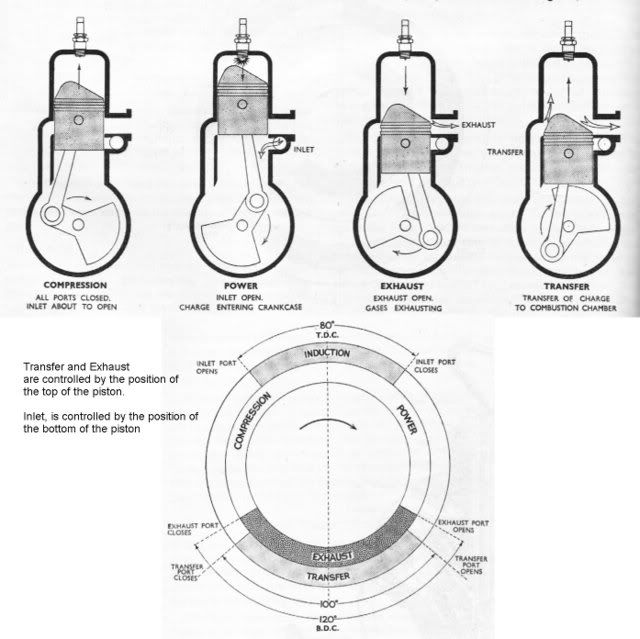
Looking at your original and revised timing diagrams, I can understand the change to the INLET timing…. that makes perfect sense given the larger port opening.

What I don’t understand though is why the exhaust, transfer, and sub-piston induction timing have changed…. (Unless you have changed the piston geometry or something else).

The revised transfer port PCD location/angles should not have changed the opening/closing position/angles…… the steeper entry (drilling) angle was primarily to give more crankcase-sealing surface under the exhaust flange but the top of the port (in the cylinder wall) should still remain in it’s original location.
The other advantage of the steeper angle is that the fresh (incoming) charge will be directed more towards the top of the cylinder… and away from the open exhaust ports…. Thus helping to purge any remaining spent gasses.

Since I can see no dimension changes to the exhaust port, either in location or height from the crankshaft centre and the exhaust port remains the same 0.2890” I am at a loss as to why the exhaust timing has changed.
Just as with the TRANSFER ports timing, given the same port location, this/these would be determined by the top edge of the piston.

Similarly, the same goes for the sub-piston induction, since the bottom of the piston relative to the exhaust port determines this.

HAVE you changed the piston dimensions?… or perhaps the con-rod length?, or the location of the gudgeon pin (wrist pin) in the piston relative to its length?

DAH!!!…….. WHAT GIVES on this?????? :-\ :-\

The overlap between the INLET opening and TRANSFER closing IS a problem….. Especially since the EXHAUST ports are also still OPEN.
This will allow the inlet to suck some of the fresh charge and/or some fresh air (via the open exhaust ports) back into the crankcase and reduce the draw through the carb…. Leading to a weaker charge in the crankcase for the next cycle.

This, however, can be remedied quite easily by changing the INLET port location/angle on the crankshaft to 53deg BTDC (which should give a timing gap of 0.5 deg between TRANSFER CLOSING and INLET OPENING) or 53.5deg BTDC, which should bring the timing to equality.

I would go with the 53 deg BTDC.

Naturally this will also alter the INLET closing point to 21 deg ATDC but, since you are in the sub-piston induction part of the cycle; that should not present any real problem.
This will not alter any of the other port timing.

Having said this….. There may be some mileage in reducing the sub-piston induction period if you find that you are getting a consistent weak mixture ….. this can be done by making the length of the piston skirt (below the gudgeon pin (wrist pin)) a little longer…. However this can be done at a later date…. if necessary. (Make a new piston).

Keep going my friend, you are almost there. :bow: :bow: :bow:

Best regards.

Sandy ;D ;D ;D ;) ;) ;)
 
Sandy,

Thanks for everything. I have attached the latest timing diagram and after a bit of fiddling around advancing the inlet port from mid point to TDC 55.5 to 48 mid point to TDC have arrived at a no overlap setting. Also attached are all the engine measurements relative to this.

The timing calculator is from Ron's site (http://www.modelenginenews.org/) and always gives slightly different answers from those obtained using CAD. From what I can gather this has to do with the fluid dynamics incorporated into his calculator.

Best Regards
Bob

View attachment M10time.pdf
 
;D ;D ;D

Hi Bob,

Great stuff, well done.

From what I can gather this has to do with the fluid dynamics

?Would this be the AMBER NECTER or the other one? :D :D :p :p :big: :big: :big:

Well that's the theory part sorted, now all you need is to build it......... Oh!..... and more AMBER NECTER. ;D ;D

Best regards.

Sandy ;) ;D ;D
 
SandyC said:
Well that's the theory part sorted, now all you need is to build it......... Oh!..... and more AMBER NECTER.

Thanks, I am a definite fan of inspirational and medicinal amber nectars of any persuasion even scotch whiskey. :big: :big:

Best Regards
Bob
 
Hi All,

Yet another update as the build progresses and I find where things fit as drawn and on the job mods to make things drawn as fitted. ::) ::)

Best Regards
Bob

View attachment Maryak10.pdf
 
Hi,

Have added another page re the Venturi and Throttle/Spray Bar.

The Venturi is drawn as made and the Throttle/Spray Bar are my starting points for making it.
wow.gif


Again draw as you machine as you draw.............etc.

Best Regards
Bob

View attachment Maryak10.pdf
 
Back
Top