The Junior

Home Model Engine Machinist Forum

Help Support Home Model Engine Machinist Forum:

This site may earn a commission from merchant affiliate links, including eBay, Amazon, and others.

Gazzaleach

Active Member
Joined
Jan 11, 2013
Messages
31
Reaction score
9
Hi Guys,
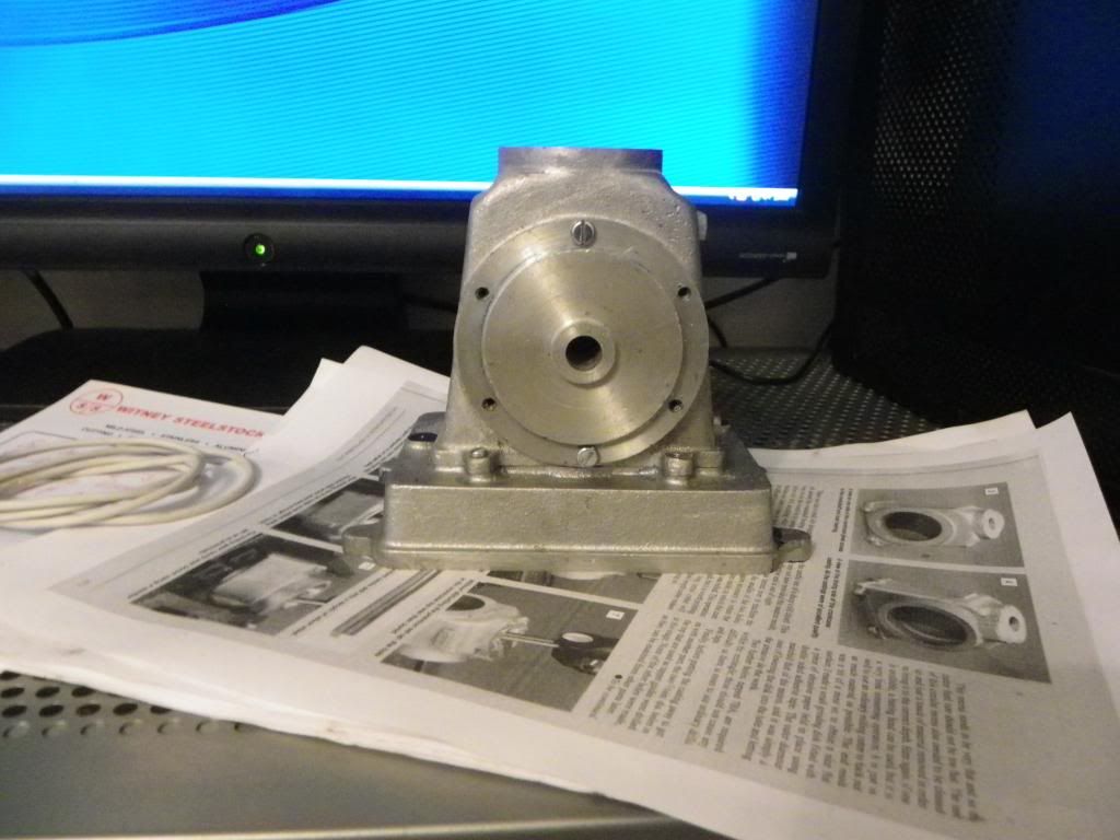
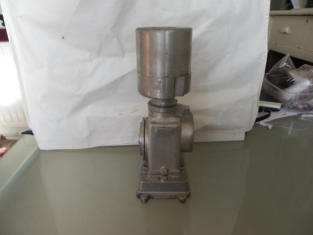
Well my flame eater is almost finished I had to order some better bearings today to complete so while I have a little down time I thought I would dig this little model out which is something I started about 7-8 years ago.

At the time my only machine was a Warco lathe/mill combo so the parts that have been started are going to need a little fettling but this is not going to be a rushed job and will try and do a bit when time allows, Im currently converting all the drawings to metric.

Now the real down side is that over time things have gone missing and this includes the two flywheel castings,con rod casting, and the timing plate casting and also the number two drawing, I spoke to the company that made the kit and they want almost £80 for two flywheel castings which i`m not prepared to pay so I shall be making all the above missing parts from bar stock or plate. They also wont supply me with the missing drawing unless I buy said castings :wall:.

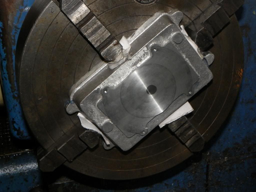
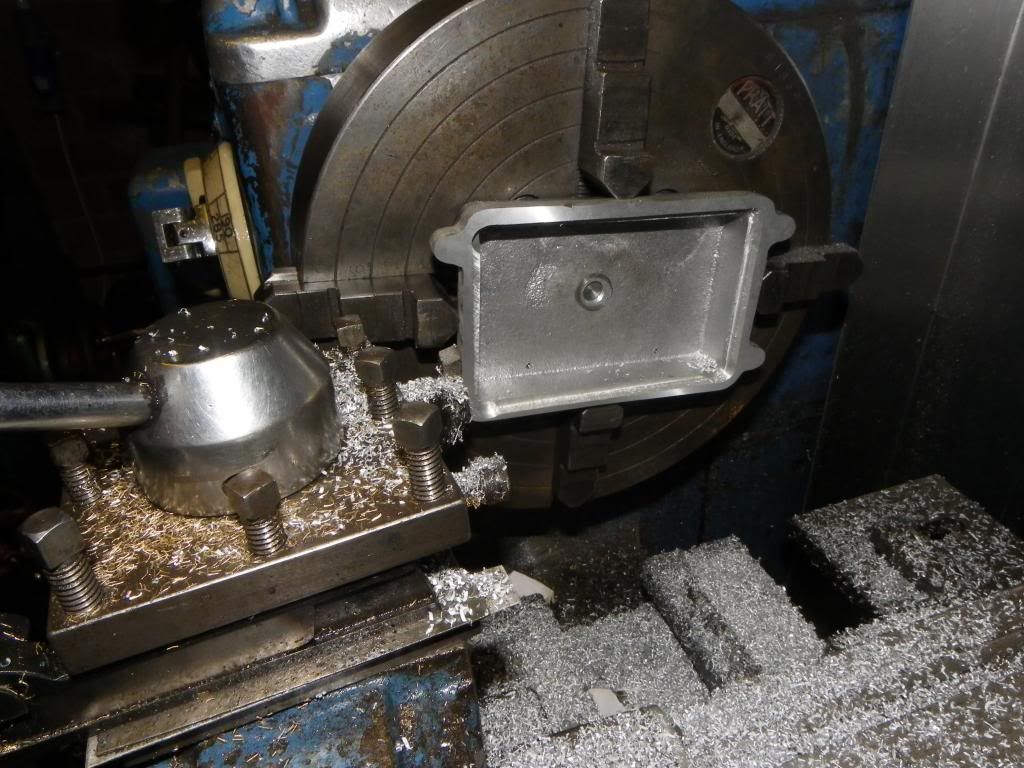
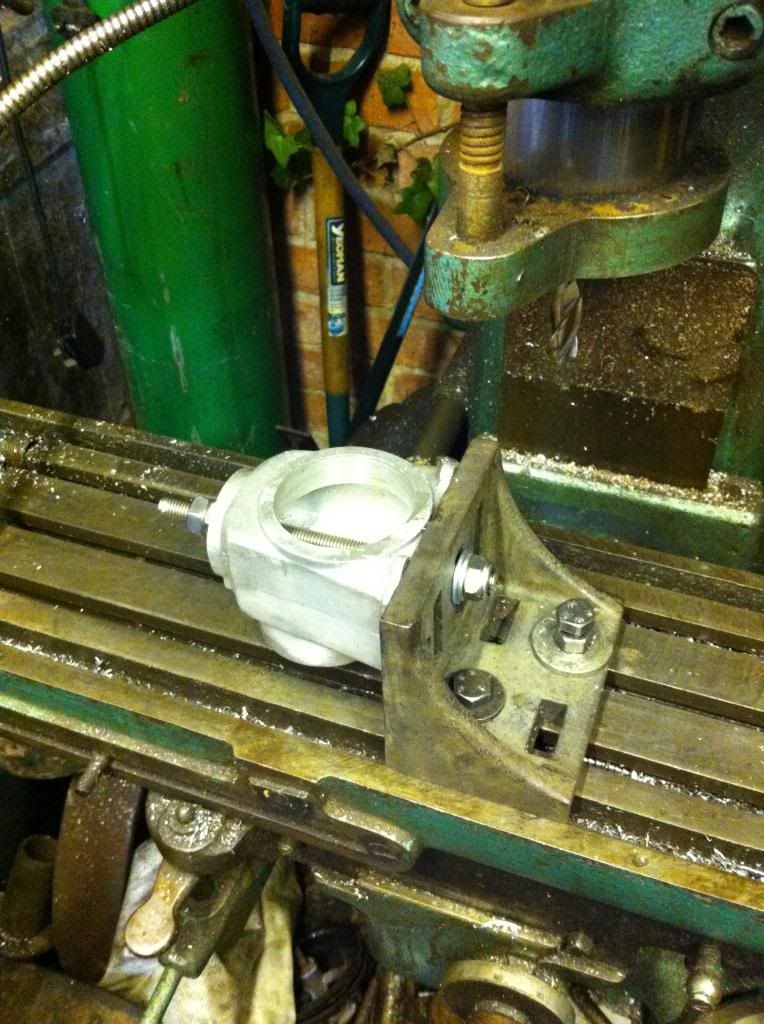
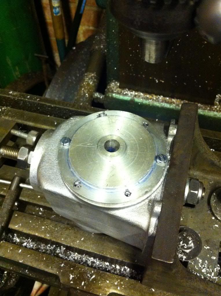
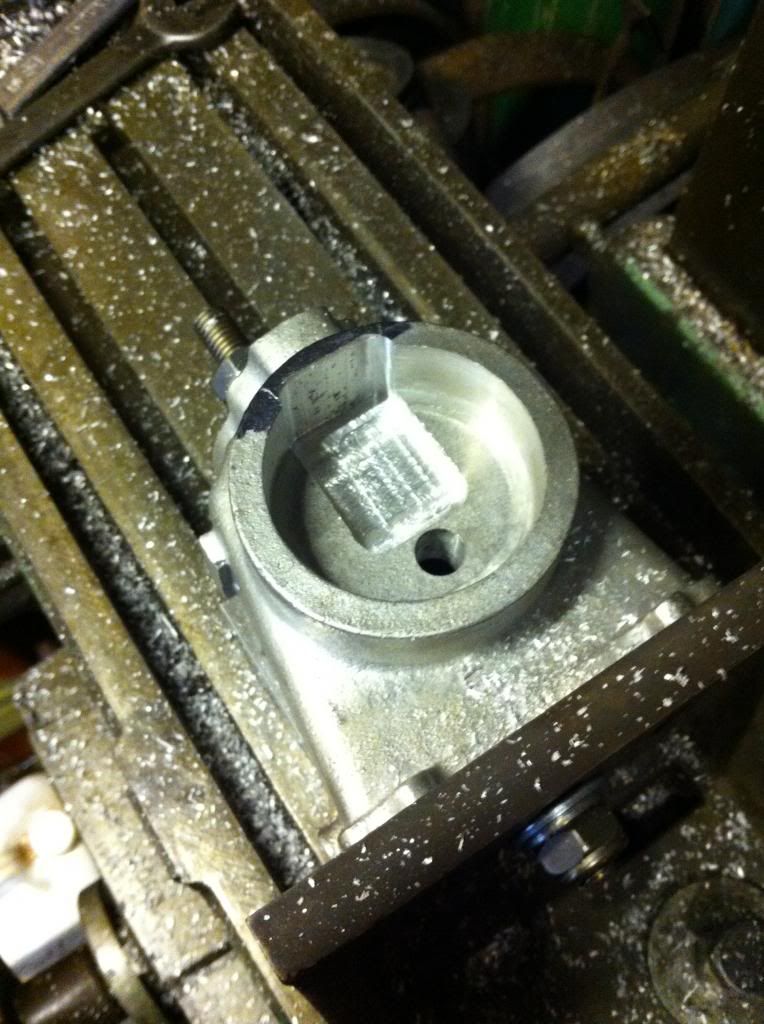
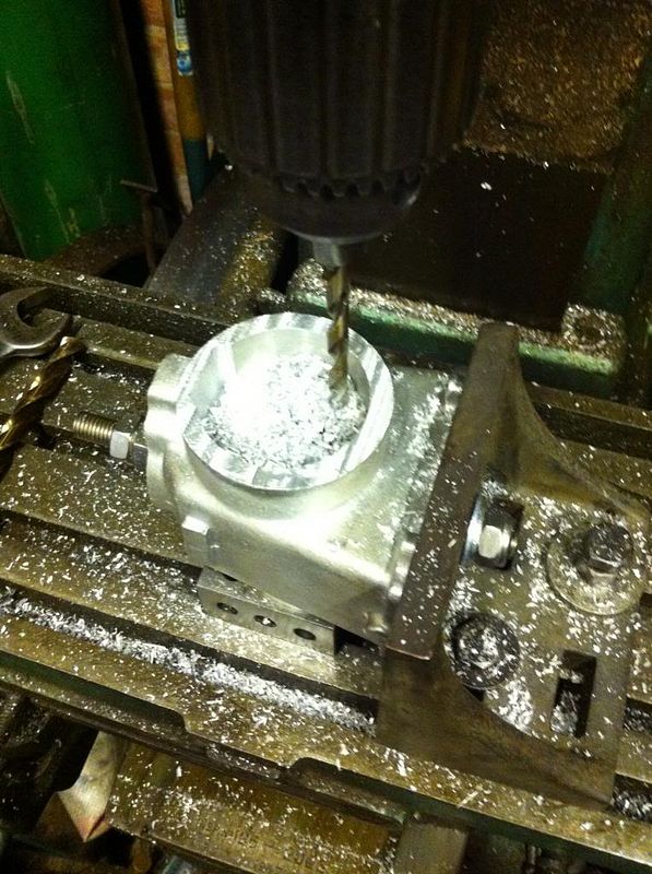
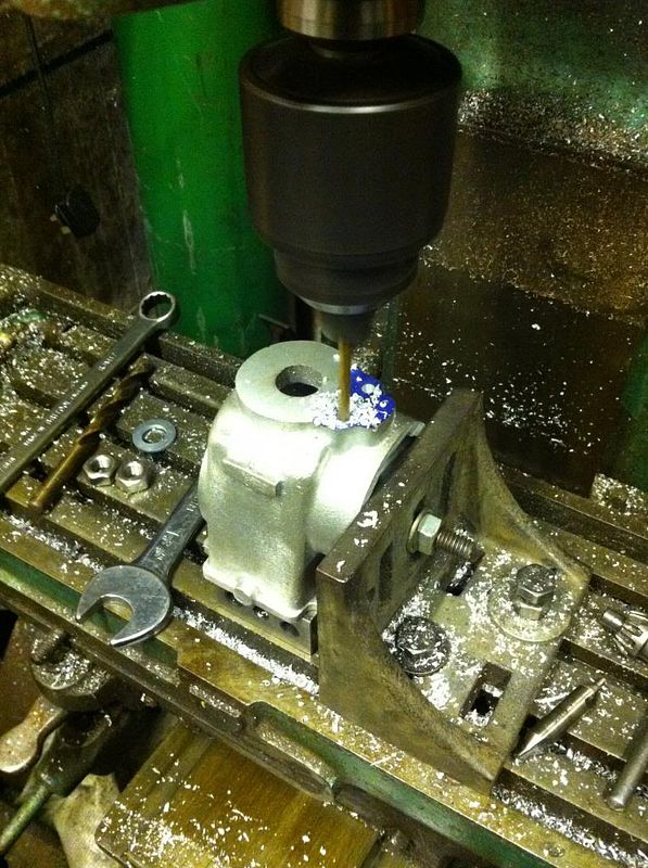
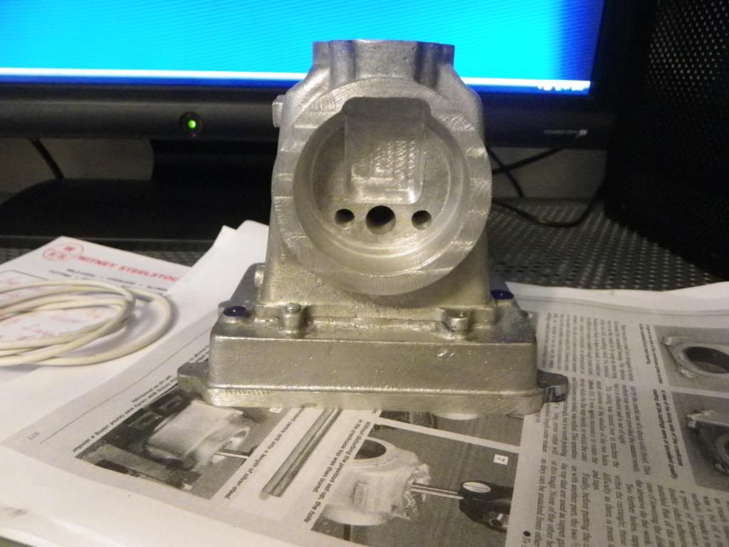
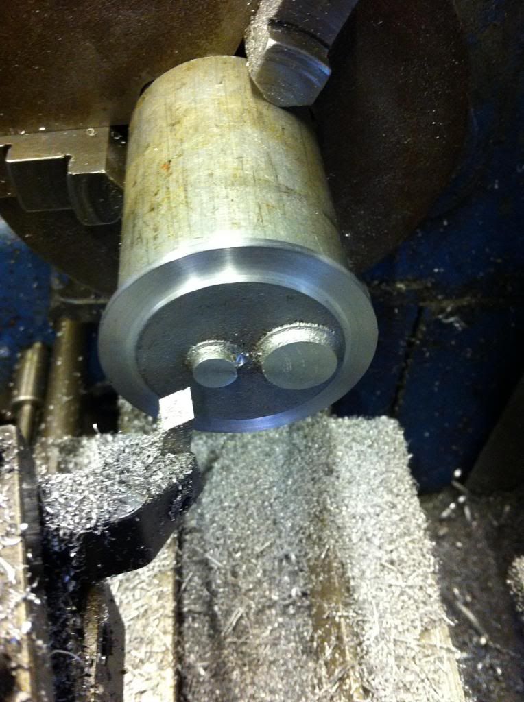
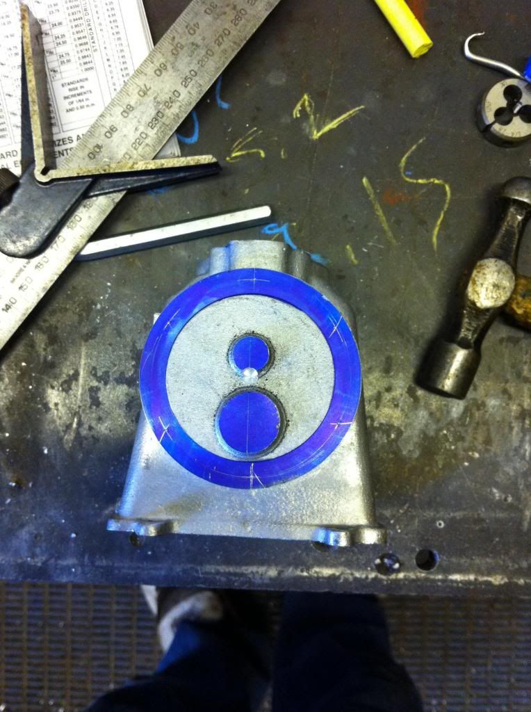
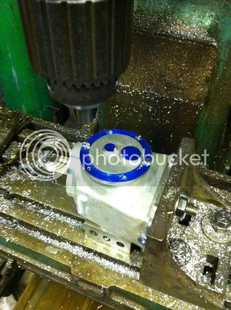
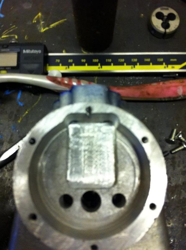
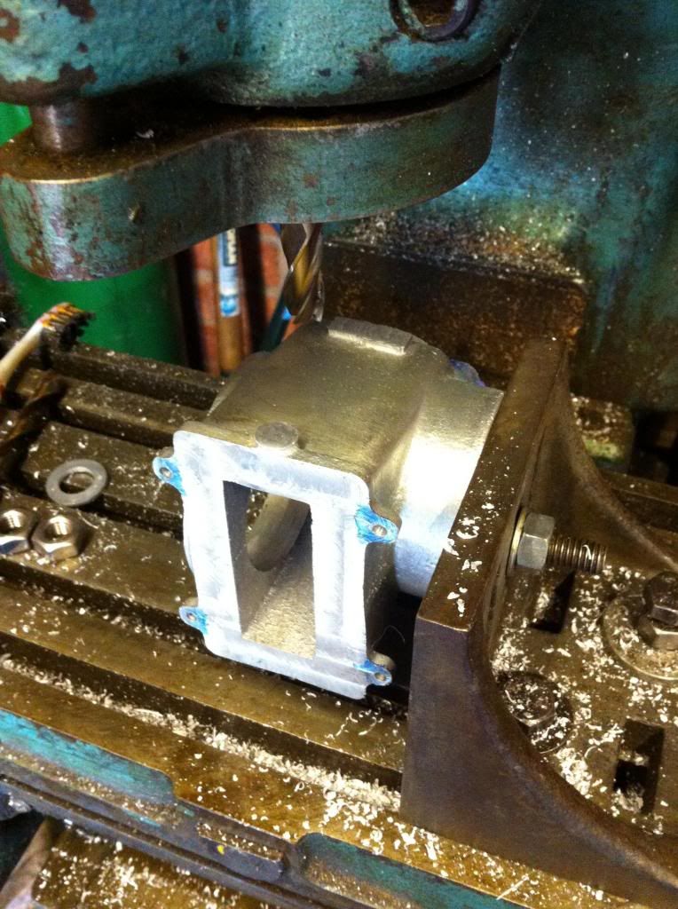
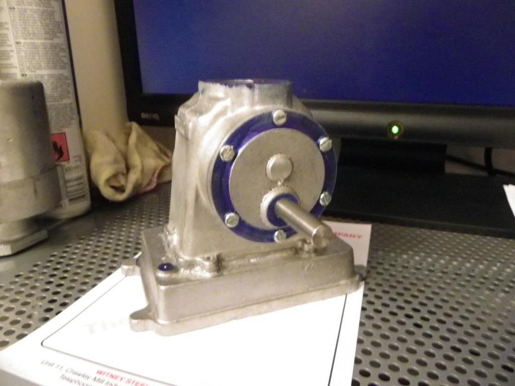
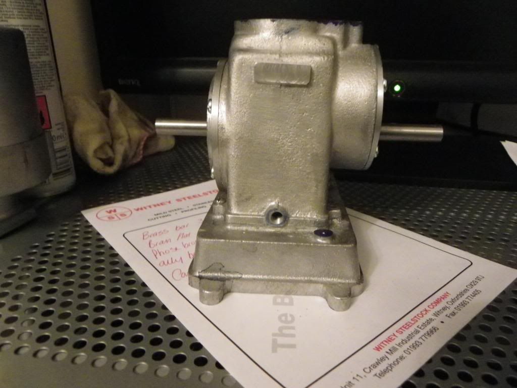
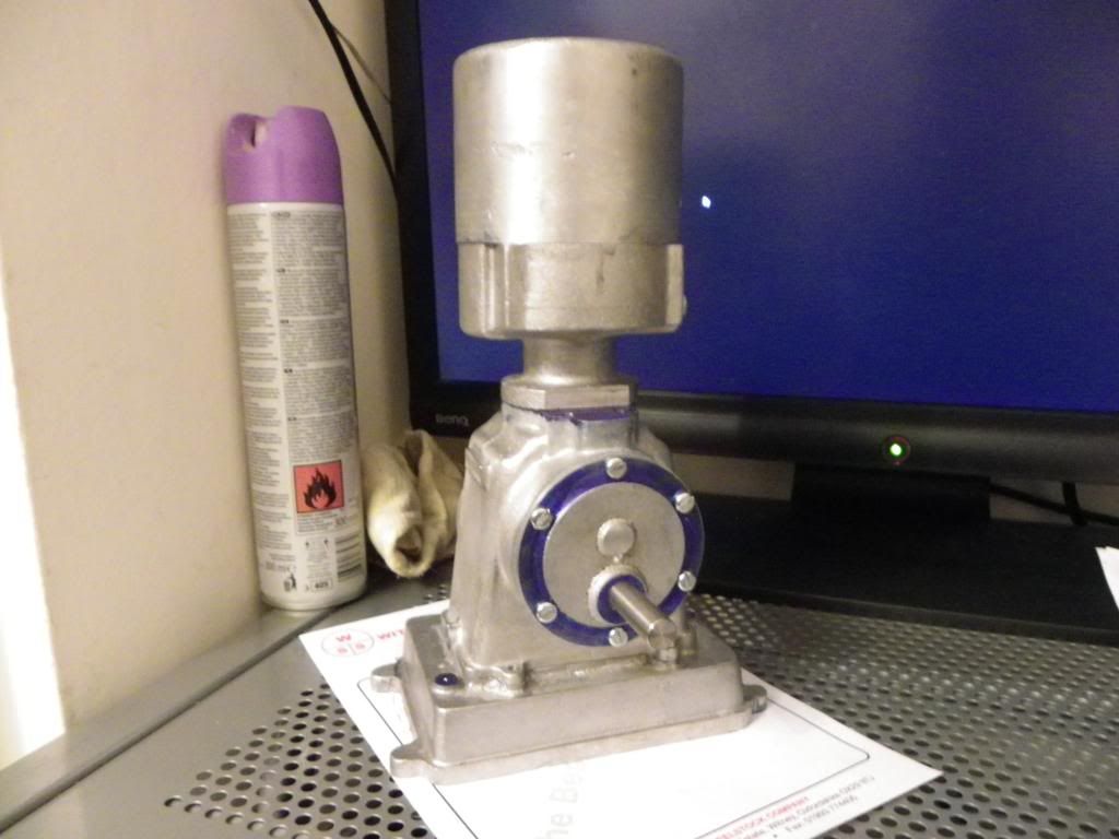
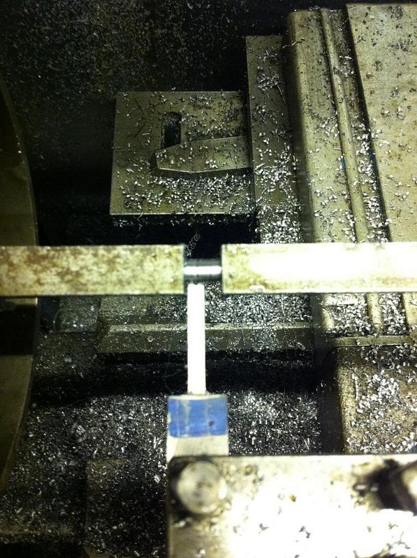
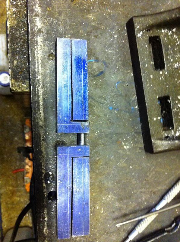
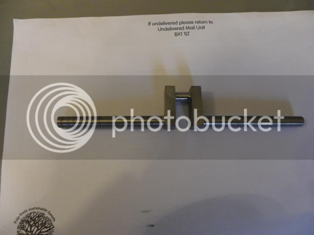
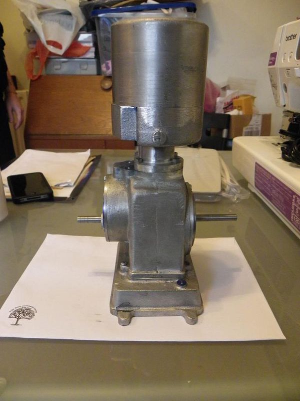
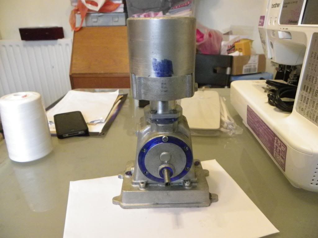
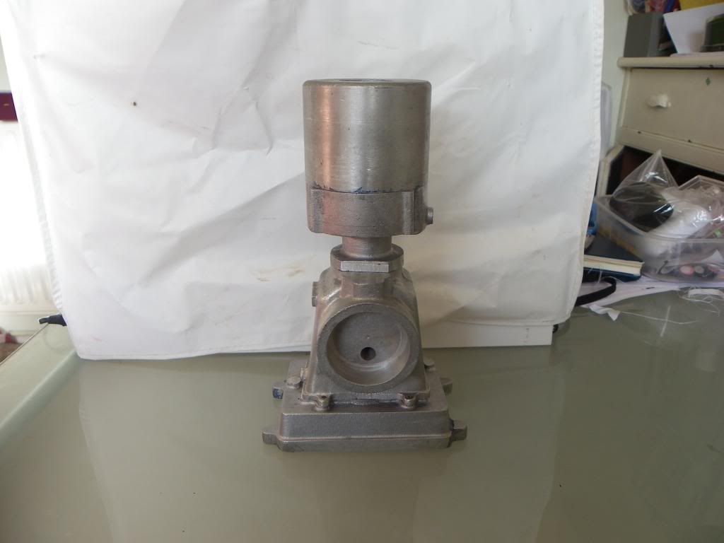
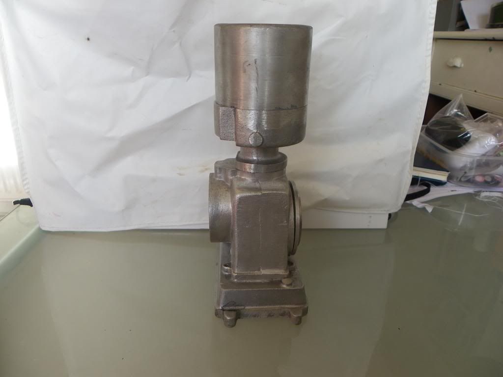
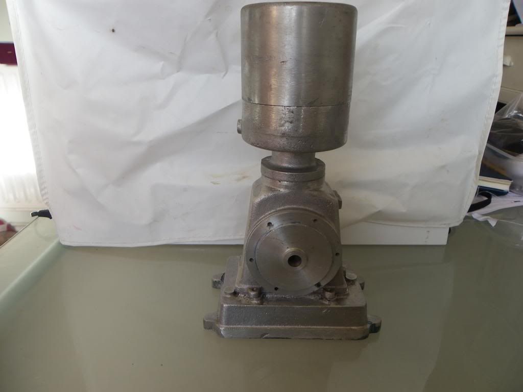
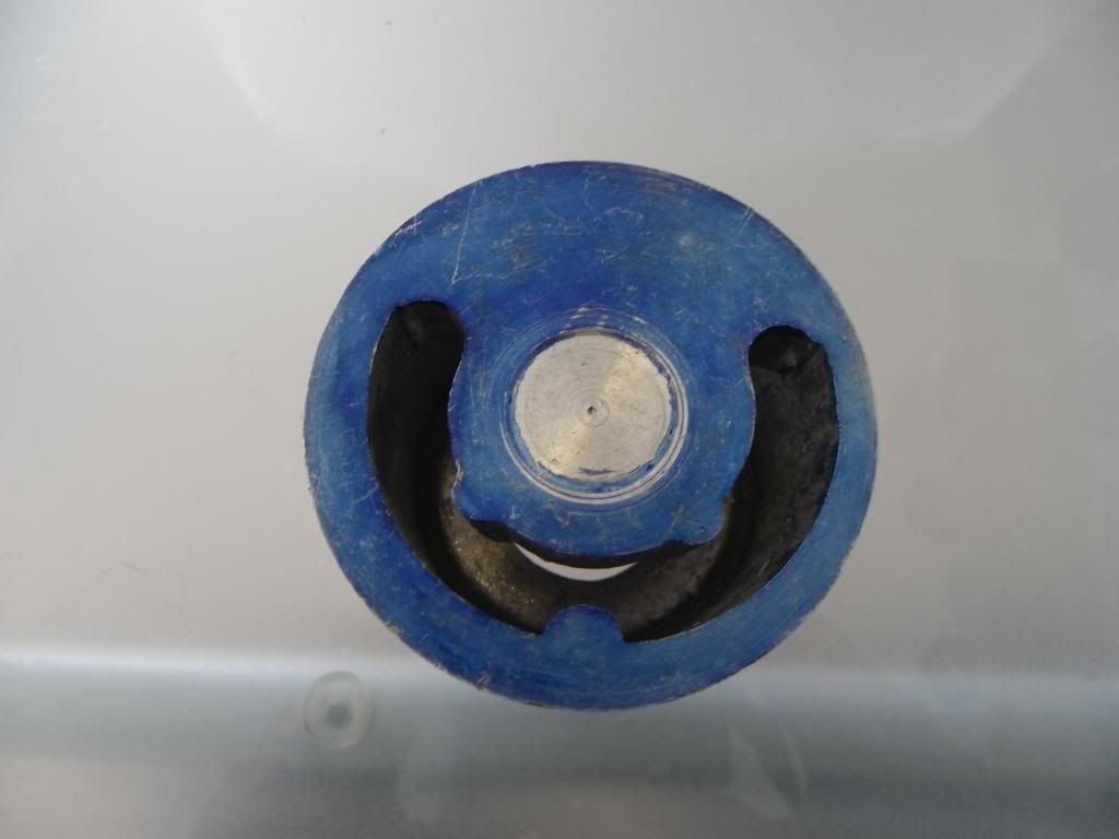
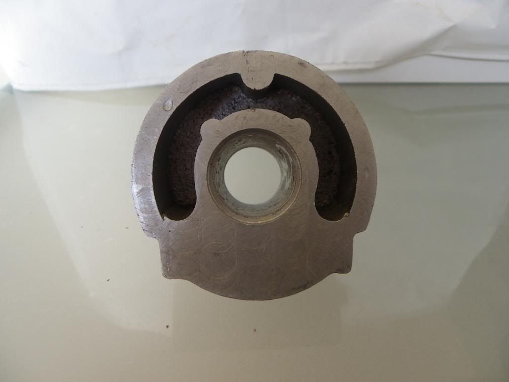
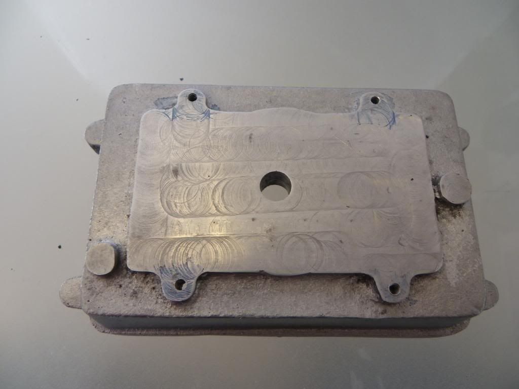
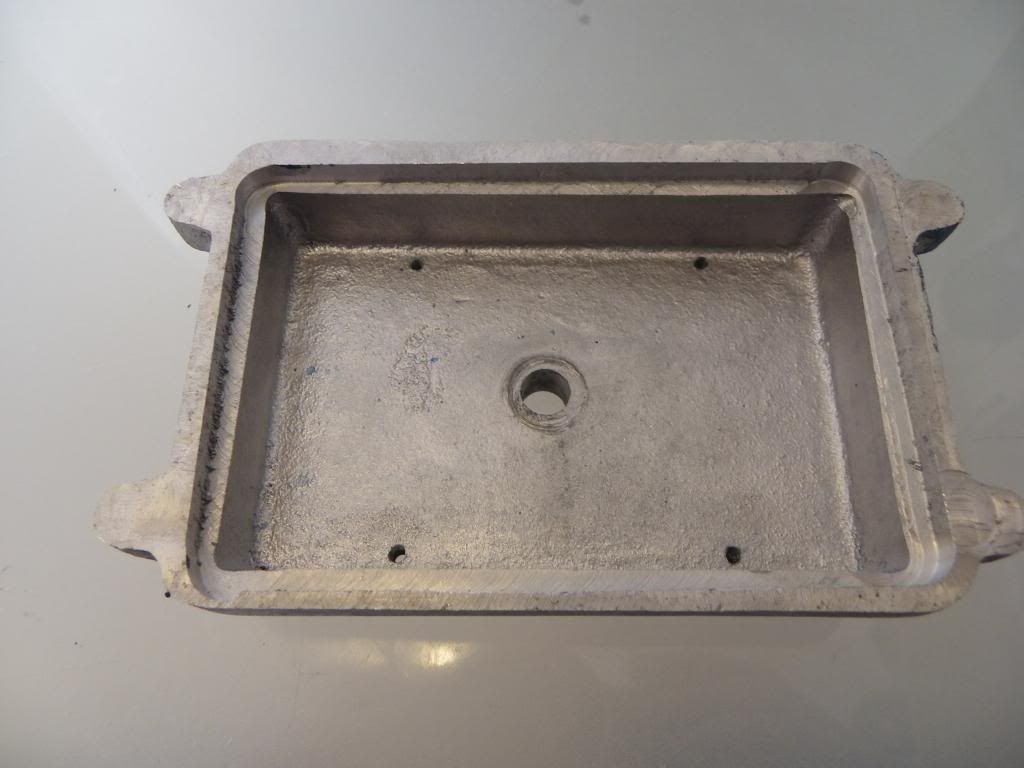
Below are some pictures and again any advice would be great .

cheers Gaz


IMGP0004_zps475e3e61.jpg


IMGP0003_zpsdbc73b29.jpg


IMGP0002_zps7502bafc.jpg


IMGP0001_zps87864f21.jpg


IMGP0006_zps5e78ead9.jpg


IMGP0007_zps99c7f206.jpg


IMGP0008_zpsdefb9593.jpg


IMGP0009_zps9415c722.jpg
 
Last edited:
You are 'lucky' that the flywheel castings have gone astray. They would have been ali, and the engine will struggle to run using them, although there have been dodges to get round the obvious lack of weight. The new castings are cast iron.

Stan Bray did a write up on constructing this engine in ME during the '90s. You may be able to get copies and find out the missing dimensions from there. I'm away from home at the moment, but when I get home I could look up the issue numbers for you, if required.

Dave
The Emerald Isle
 
Cheers dave,
I did have a copy of the build diary but that has also gone missing, I plan to make the flywheels from cast iron bar stock my only big challenge will be the piston rings is there a how to on this forum? I wouldn't say good work so far there seem to be loads of mistakes but lucky for me I couldn't of read the drawings correctly when I first started as there is plenty if material to remove and start a fresh.

Cheers Gaz
 
PM me if you want any of the articles scanned.

You could possible also get away with stuart flywheels or even the cheapies that RDG do, think they have one about 4" dia
 
Hi Jasonb
I've sent you a quick pm also I was looking at the cast flywheels you suggested not sure though, the cost of the cast iron with postage is around £20 I guess it all boils down to time and effort.

Cheers gaz
 
Just a little update I thought I would start by cleaning up the base plate and also plug the hole that was made when i had no real understanding of how to hold/machine this part.
So I started out tapping the hole M10x1 and as I did not have a length of bar the right size in aluminium I made the plug from stainless and fitted it with some loctite.

The next task was just to machine the two faces to the correct size, I then came in doors and laid out all the holes to be drilled which i may do tomorrow its far to cold in the workshop to play today.

cheers Gaz


IMGP0003-1_zpsf2293e8c.jpg


IMGP0004-1_zps4b155119.jpg
 
Much better finish on the parts already.

J
 
Made a little progress on the crankcase casting today, Ive been putting this off for a while as i was unsure if i could do it.

Started off ensuring the bottom of the casting was flat and mounted it to an angle plate ready to drill and tap six 5 BA holes for one of the crankcase end plates.

IMG_0185_zps49958bae.jpg


The cover already had the holes drilled so was just a matter of spotting through and drilling and tapping one at a time.

IMG_0186_zps398d89b8.jpg


whilst in this set up the face was trued up with flycutter, the casting was then flipped over ready to machine the space for the cam followers, This was a little awkward to see what your cutting!

IMG_0187_zpsf749e9bc.jpg


Again while in the setup the face was trued up and the two 1/4 holes for the oil passage was drilled.

IMG_0188_zps1cb83da1.jpg


The last task of the day was to drill the two tappet follower holes on top of the casting the other hole for the breather was left untill later.

IMG_0189_zps98eceb3e.jpg


below are some pictures of the progress so far it all still needs cleaning up and tool marks removing.

IMGP0001_zpsd89f4f7f.jpg


IMGP0002_zps8757e582.jpg


IMGP0003_zps012353bf.jpg


cheers Gaz
 
Cheers Dave,


I found the timing gear cover this morning which was a bonus machining it was a pain in the arse but turned out ok in the end.

IMG_0195_zps11c8cdf0.jpg

Started out by machining the back side flat in the 3 jaw light cuts as there was not a lot to hold onto. I then chucked up a length of aluminium bar trued the face and super glued the timing cover to it. Again some light cuts to the required thickness.

IMG_0197_zps5700b60f.jpg

IMG_0198_zps71977077.jpg

All the bolt holes where layed out and the cover again super glued to the crankcase.

IMG_0199_zps969ce474.jpg

The holes where then drilled and tapped 5 BA same as the other side.

IMG_0200_zps54642716.jpg

when the cover was removed one of the holes was on the edge of the casting now the thread holds when everything is tightened up so should i leave it or try and fix it?

IMG_0201_zpsc39bbb49.jpg

With the crankcase mounted on the I trued up the boss on the side for the throttle linkage and also drilled and tapped the oil drain hole.

IMG_0190_zps1fa4d446.jpg

IMG_0191_zps1ec29ea8.jpg

IMG_0192_zps8740fe61.jpg

IMG_0193_zpscc6c40ad.jpg

Last task for today was to drill and ream the hole for the crankshaft.
IMGP0002_zps59ef3fa2.jpg

IMGP0003_zps7831db08.jpg

IMGP0005_zpsdcc866aa.jpg

Hope this isnt becoming to picture heavy and pointless.

Many thanks Gaz
 
There is no such thing as too many photos Gaz!
Im following along.
Pete
 
Gaz

I love to see other people's photos primarily to see the setups and also the finished product. So, keep them coming.

Vince
 
when the cover was removed one of the holes was on the edge of the casting now the thread holds when everything is tightened up so should i leave it or try and fix it?

IMG_0201_zpsc39bbb49.jpg

Many thanks Gaz

Gaz

I'm a bodger, so don't take what I say for Gospel!

The screw seems to be holding some, so you could use some car body filler or better still JB Weld if you have any for a belt and braces job. Just fill in the broken-through part of the wall and if there is room, spread a bit more in the crank cavity to give it a bit more strength. Bolt on the cover again with the other screws and run the tap through cover and body. Should then be fine.

Dave
The Emerald Isle
 
Cheers for all the comments guys, as regards to the half a bolt hole i think i shall leave it untill the cam and gears are in place then check for clearance.

Not much progress over the last couple of days i have managed to get all the castings bolted together and ive made the crankshaft.

few pictures below cheers Gaz

Oh one last thing how do you go about cleaning the ends of the crankshaft up my fixed steady is far to large to hold, so would the mill be ok?

IMG_0204_zpsbd30fbf4.jpg

IMG_0205_zps3e60f0ae.jpg

IMGP0002_zps92e640aa.jpg

IMGP0004_zps49ebd88d.jpg

IMGP0005_zpsd9145979.jpg
 
Back
Top