- Joined
- Dec 2, 2008
- Messages
- 971
- Reaction score
- 8
Happy New Year to all
New year and a new engine begins to take form.  This is a further development of the wobble plate engine that occurred to me as I was finishing up the Weeble that I posted last month.  I have spent a fair amount of time studying the various configurations of axial cylinder engines like the swash plate, the dynacam, the flexible rod, the Z-axis, the bent axis, the elbow and other types of wobble plate mechanisms. There have been many critical evaluations written that mainly focus on high friction loss that have doomed these engines to the category of curiosity.  So being the curious type, I jumped in to see for myself.
The first engine of this type that I built was the Chevron 10 that I posted here previously.  It is a perfect example of the critics viewpoint.  High friction taken to the max.  Even allowing for the poor execution of the design, it was a nightmare to get it to run at all.  I have heard that builders of the elbow engine say that they have to be built "loose" and becauseof that the leak air and oil.
I started looking at swash plate engines like the Mitchell Crankless Slipper Plate engine featured in Home Shop Machinist.  The builder of this engine says that the slipper plate bearing must ride on a  continuous oil film on the plate and at high RPM, throws oil everywhere.  I guess that is why commercial swash plate pumps and motors are fully enclosed, to provide an oil bath to the components and not to the observer.
I the switched to wobble plate designs and focused on the ball pivot mechanism because of its simplicity.  I designed and built the "Weeble" and was amazed at the relative lack of friction.  Even roughly built, it spins freely and achieves high speeds easily.  I have not published any plans for the Weeble but would be happy to post a .pdf or .dxf of my working drawings if anyone is interested.
The Weeble is a ball pivot swash plate design that uses a single ball and socket to control the pivot point of the wobble plate and two control rods that prevent the plate from revolving and getting its arms all tied in a knot.  That is one of the things that bothers me about this engine type.  The need for an added mechanism to prevent rotation of the wobble plate.  A Google Patent search turns up many examples of wobble plate mechanism and all require some gimicky looking mechanism that destroys the symmetry and seem like an inelegant solution to the problem.  My first approach to the problem was a fifth arm on the spider with a ball at the end that traveled in a fixed channel on the frame.  I ditched this in favor of the two brass rods that capture one of the spiders arms.  It works just fine but I just don't like the looks of it so I did my best to hide it.
A  few days spent on the boat before Christmas showed me the answer. Hanging on a bulkhead was a brass oil lamp that is free to tilt both fore and aft as well as athwart ship but it dosn't rotate! It is mounted in a gimbal, two pivot points at right angles that allow full wobble but no rotation.  Gears started turning in my head.
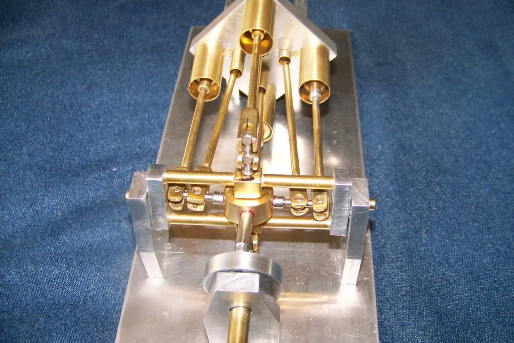
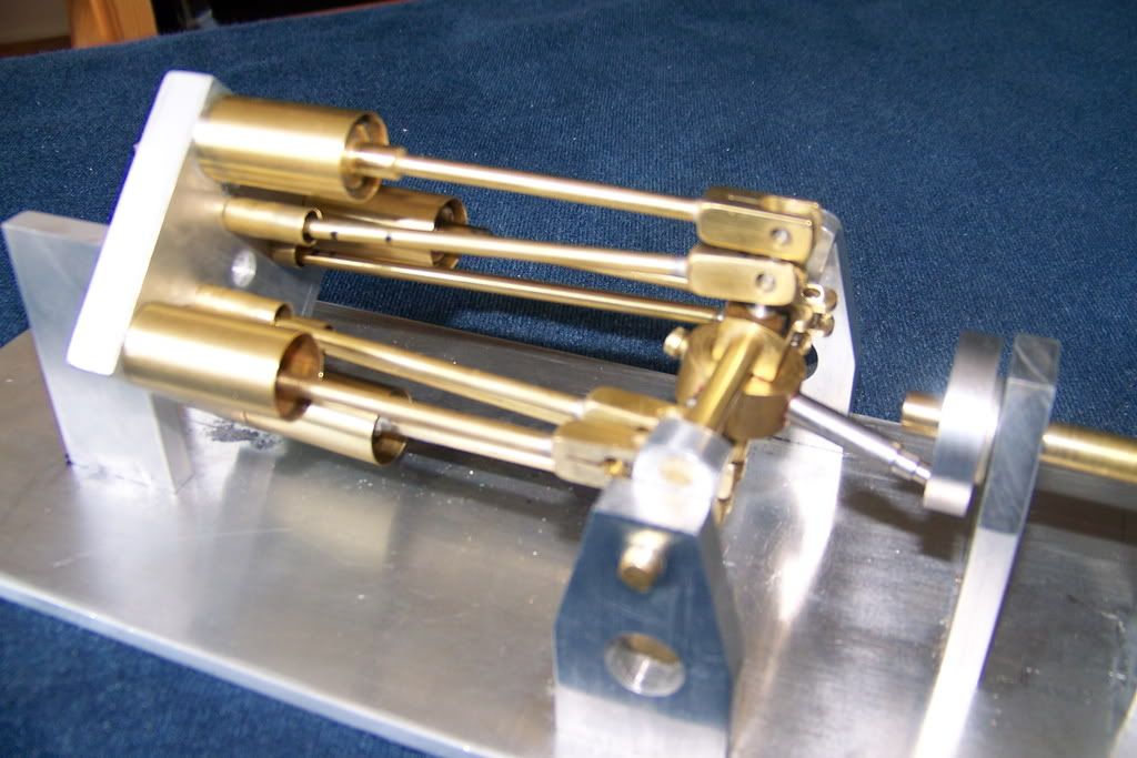
I have not completely settled on the whole design but I had to build a gimbaled wobble plate to test my theory.  Several designs that looked good on paper had serious limitations in execution. Here is what I have settled on for the gimball mechanism.  It provides wobble without rotation and is completely symmetrical. 
The completed gimball engine will borrow many design elements from the Weeble but I hope to be able to eliminate the other design element that bothers me. The rotary valve will be replaced by individual piston or spool valves. The design of the valve gear is my next hurdle.  Shop time is limited so this may be slow.
Best to all
Jerry


New year and a new engine begins to take form.  This is a further development of the wobble plate engine that occurred to me as I was finishing up the Weeble that I posted last month.  I have spent a fair amount of time studying the various configurations of axial cylinder engines like the swash plate, the dynacam, the flexible rod, the Z-axis, the bent axis, the elbow and other types of wobble plate mechanisms. There have been many critical evaluations written that mainly focus on high friction loss that have doomed these engines to the category of curiosity.  So being the curious type, I jumped in to see for myself.
The first engine of this type that I built was the Chevron 10 that I posted here previously.  It is a perfect example of the critics viewpoint.  High friction taken to the max.  Even allowing for the poor execution of the design, it was a nightmare to get it to run at all.  I have heard that builders of the elbow engine say that they have to be built "loose" and becauseof that the leak air and oil.
I started looking at swash plate engines like the Mitchell Crankless Slipper Plate engine featured in Home Shop Machinist.  The builder of this engine says that the slipper plate bearing must ride on a  continuous oil film on the plate and at high RPM, throws oil everywhere.  I guess that is why commercial swash plate pumps and motors are fully enclosed, to provide an oil bath to the components and not to the observer.
I the switched to wobble plate designs and focused on the ball pivot mechanism because of its simplicity.  I designed and built the "Weeble" and was amazed at the relative lack of friction.  Even roughly built, it spins freely and achieves high speeds easily.  I have not published any plans for the Weeble but would be happy to post a .pdf or .dxf of my working drawings if anyone is interested.
The Weeble is a ball pivot swash plate design that uses a single ball and socket to control the pivot point of the wobble plate and two control rods that prevent the plate from revolving and getting its arms all tied in a knot.  That is one of the things that bothers me about this engine type.  The need for an added mechanism to prevent rotation of the wobble plate.  A Google Patent search turns up many examples of wobble plate mechanism and all require some gimicky looking mechanism that destroys the symmetry and seem like an inelegant solution to the problem.  My first approach to the problem was a fifth arm on the spider with a ball at the end that traveled in a fixed channel on the frame.  I ditched this in favor of the two brass rods that capture one of the spiders arms.  It works just fine but I just don't like the looks of it so I did my best to hide it.
A  few days spent on the boat before Christmas showed me the answer. Hanging on a bulkhead was a brass oil lamp that is free to tilt both fore and aft as well as athwart ship but it dosn't rotate! It is mounted in a gimbal, two pivot points at right angles that allow full wobble but no rotation.  Gears started turning in my head.
I have not completely settled on the whole design but I had to build a gimbaled wobble plate to test my theory.  Several designs that looked good on paper had serious limitations in execution. Here is what I have settled on for the gimball mechanism.  It provides wobble without rotation and is completely symmetrical. 
The completed gimball engine will borrow many design elements from the Weeble but I hope to be able to eliminate the other design element that bothers me. The rotary valve will be replaced by individual piston or spool valves. The design of the valve gear is my next hurdle.  Shop time is limited so this may be slow.
Best to all
Jerry


")