The Boxford Files

Home Model Engine Machinist Forum

Help Support Home Model Engine Machinist Forum:

This site may earn a commission from merchant affiliate links, including eBay, Amazon, and others.

CrewCab

Well-Known Member
Joined
Apr 21, 2008
Messages
1,175
Reaction score
8
Some of you might have noticed from another thread that this hunk of "old iron"


boxfordall.jpg


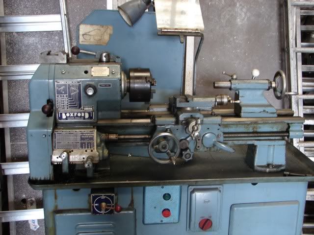
is about to take up residence in my workshop


this lathe could well be older than me :eek: ........... certainly takes me back to my schoolboy machining days ;D

I'd been thinking of changing the little 9"x20" to a British version ......... mainly to gain a little more mass and to have the benefit of a gearbox and power feeds. I'd been looking at a lot of Myfords (which seem to command very high prices) but a big thank you to Bogsie :bow: for putting me onto the trail of the Boxfords, they seem a lot more machine and can be had at more sensible prices.


Any way, it's a Boxford AUD Mk2, which is a clone of the 9" Southbend for our American listeners ;)

Spot the similarities

Southbend1.gif


There is a wealth of information about these on the web but some of it is a little conflicting, the AUD is the model "A" (Screwcutting Gearbox and Power feeds in both directions) with UD ....... UnderDrive, the motor is in the base / cabinet. The total weight is over 600lbs so that's the first hurdle.

Transporting it home should be OK, it can be loaded into my van with a fork lift, at my end we can have the use of an engine lift to get it out ......... but ........... to get it into the workshop it has to go through 2 x single doorways up 2 steps, then down one step, so methinks dismantling it may be the best way forward.

In principle it seems straightforward, but two points concern me a little ..............

"1) If the lathe has a gearbox, leave it in place - and try not to remove a lathe from an under-drive stand; a compound was used to stop coolant getting into the wrong places and effectively sticks the lathe down; once broken the hardened sealer has to be chipped off and the joint remade.
2) Apparently the drive belt is continuous and will need to be cut."


So ......... does anyone out there actually have experience of taking one of these apart .......... or ...........am I going to be the HMEM Guinea Pig ::)

CC

 
Congrats! It looks to me like you have yourself a real gem there!

My wheels are turning here... Do you have to make any corners once you get inside, or is it a straight shot to the shop? I have a possible idea for you that might help move the machine. If you can get the lathe off of the stand, you might be able to build a skid for the lathe and use that for the move. Let me know your situation and I'll draw up a quick sketch.
 
I recently got a Warco 280VF which weighs about 190kg, as the engine crane would not fit through my side gate I bolted the lathe to some 2" thick timber and then used several bits of 2" PVC pressure pipe to roll it round the back to the workshop, scaffold pole would probably be a bit better as even the thick wall of the pressure pipe was giving a bit.

Jason
 
Wow,
I never read those warnings :-\

First off on the two I have moved for others if there was any sealant it had long gone and in any case silicone is a far better modern sealant that the gorilla snot they had years ago.

Drive belt, one has link belt so that was easy to split. on the other I took the countershaft of it's plumber bearing and slipped the belt off leaving it dangling from the lathe headstock.
Once apart everything was moved on a small pallet and pump up truck and then re-erected with the trusty folding crane.

Two good men can do this without the pump up truck and crane.

.
 
Thanks guys, the lathe weighs 276Kg / 608lbs so it's a tad lardy, I suspect the cabinet itself is fairly substantial ...... weight wise ::)

Stripping it down might not be a bad idea anyway but if I can get it straight into the workshop first that would be nice.

Access is .......... through side door of house (up 2 steps) into utility room, 90o Right Turn, straight on for 10 feet, (and it's only 3 feet wide), down 1 step (only 2") into workshop, straight on for 12 feet then rotate 90o to position on back wall.
I'll fire up Crap-O-Cad and do a sketch ;D

CC
 
Cheers John, sounds like it's quite do-able then, must admit I thought silicone would be the material of choice, I suppose it depends on the year of manufacture ............ I'll try and find out once I get the serial number.

Dave
 
If it's anything like Harrison's used it's more like that old Boss White they glued apprentices to steam pipes with.
Dries like concrete and you need a welders chipping hammer or a Kango to get off.


Up a step, thru a door 10 feet to the right etc.
Sounds a doddle. if you can't get it onto a trolly or such like don't bother with rollers they are a total waste of time, you spend more time poking the band things under then a little.

Get 2 lengths of 1/2 round bar or 3/4" black angle, vee uppermost, drop these down like tram rials and just push the machine along the rails.
The point contact will allow it to move as if on rollers and you can go 8 to 10 feet at a time, if you have to go up or down steps use two planks with shorter pieces of bar on them.

Once you have used this method you will never go back to rollers and bits of tube.

Me and Ower Gert put this into position one Sunday morning before church using only 4 lengths of 1" angle, a 3 foot pry bar and 17 cups of coffee.
The roller wasn't in the chuck at the time ;)

STEADY1.jpg


.
 
JASONB: Not trying to hijack this thread, but I was very interested to hear you own a WARCO 280vf, I'm currantly talking to WARCO about importing one of these lathes into canada so if it wouldn't be too much trouble could you please tell me how well you like this lathe, overall accuracy, dislikes, ect.
Pete
 
John Stevenson said:
Me and Ower Gert put this into position one Sunday morning before church using only 4 lengths of 1" angle, a 3 foot pry bar and 17 cups of coffee.

I'd have thought more coffee would have been required :D

Blimey John, your swarf collection probably weighs more than my lathe 8)

CC
 
Hi there
AS an ex plumber i can tell you of the easiest way to remove Boss White and most other old pipe sealants................................ heat with a blow lamp, Just hotter than warm usually works a treat you can also remake or stop a leak with this method. Just don't try it on pipes that contain flammable liquids. Actually an electric paint stripper would do equally well.

Kind regards

Malcolm
 
My thoughts on the move are to leave the lathe and stand intact. The only problem this will present is the it will be top heavy!

Two people could do the job, but to play it safe I'd have a third. I think that I would place the whole unit on a sheet of plywood that is not but a slight bid larger than the footprint of the machine, and attach it with some method (screws, bolts, straps,etc). Once you have it on a flat surface, you will be able to move it around without too much trouble. Use some small diameter plastic pipe (PVC here in the states) cut into lengths about 3" wider than the width of the machine as rollers and once the lathe is on the floor you can easily roll it where you need it to go. Have enough rollers on hand that the machine will be on three or four at all times. Just place one in front of the machine as you are moving it along. If your floor is fragile, use a couple of sheets of paneling or Masonite to protect the floor. Move one sheet in front of the other until you clear the area needing protection. Also know that there will not be enough strength in the plywood to hold the weight of the machine, but this will give you a safety margin in case things go awry.

Bring your lathe to your first doorway, and then pick it up with a hoist (assuming one can fit there; if not, then you might look at breaking the cabinet and lathe apart for the move) and set it up on some blocks that are of the same height as you kitchen floor. Place your rollers under it and move it into the kitchen and prepare for the turn. I think I would have the heavy end go in first.

The turn will be some careful persuasion to the unit to get it to slide on the pipes. Be mindful that you don't want to tip the unit, and this will be the most likely place it will happen. Once you have the machine turned the direction you need, then move it across the kitchen floor until you reach you next step. Again, have the heavy end in the direction of travel.

The 2" drop shouldn't be a huge deal, but be cautions as this is where it can run away from you. Let the lathe roll out over the drop off as far as you can to reach the balance point, and then gently let it rock down to a waiting pipe and continue forward. Stop the unit when the back side reaches the drop off. If you have the light end of the machine, then maybe two people can let it down slowly to keep from having an abrupt drop.

Once you have it on the shop floor, you are well on the way. Move it to you location, and get it close to the area you would like it to set. If yo can get your lift in the area, then do so. Remove the unit from the plywood by picking the unit up, or sliding it off (if you are sliding it off, watch the tip over hazard!) and set it down on the floor where it needs to be.


I have moved my lathe in much the same fashion, and it worked very well. I have a 13x40 and it weights around 1300lbs. I did use PVC pipe in 3/4" diameter, and I didn't have any issue with it trying to collapse. And I did it with only one other person, my wife.

As with any big move like this, have a back up plan no matter what you decide to do. Think the whole operation through, look for the snags and try to avoid them before you have your machine sitting in the middle of the kitchen! Have a contingency in place for each step of the operation (i.e. making the turn) and make sure you have the tools/materials on hand to implement the plan should you need to.

Keep safety a priority, and watch for pinch points and never let yourself get between the machine's direction of travel and an immovable surface. Whom ever you have to help, give a thorough briefing on the operation before you start, and this will make things run much smoother. It will also prepare the help for the possible hazards and they will know better of what to watch for during the move.


I hope that all makes sense! If not, then I can elaborate or make a few sketches.

Congrats on the lathe and I am looking forward to seeing some parts come off of it!

W/E
 
CC: This may sound very simplistic, but how about making a cardboard cutout of the foot print of the lathe, hand wheels and all, and then walk it through the hallway to practice which way you will turn to make the corner. If it is tight, this may save time when you actually get it into the house, you will know which direction to go at the 90* corner instead or trying and finding out the other way might have been easier.
Good Luck---don
 
First off, let me me say that you have acquired a fine lathe. I bought a new Boxford about 1970 but I think it was an older model than yours. The dealer delivered it to my shop (commercial building) so I didn't have to move it. However, it is a South Bend clone and I have moved two of those several times. A lathe is top heavy and tipping one over can be disastrous to the lathe and to the human body that it falls on.

I moved a 10 x 24 Logan underdrive into my basement shop this summer by myself, except for help with the bed. This trip was up steps 30" to the main floor, down the hall, turn to go down the stairs with a right angle turn half way down, then immediate turn at the bottom through a door. This is also an 800 pound lathe and I would not consider moving it by hand in one piece in confined areas.

I have a detached garage, so I took the lathe apart and did the cleanup in the garage before moving it into the house. Everything on a lathe is easy to take apart and put back together. I take everything off a lathe except for the headstock on the bed. Every piece can then me moved on a cheap two wheel dolly. On the underdrive model, you have to pull the spindle out to change the belt, but to move it, you only have to remove the countershaft. I removed everything from the underdrive pedestal to clean and check the components and make it light enough to move by myself. Two men can move that pedestal with the drive still inside if you have a dolly. An alternative to the cheap (made in China) rubber tired dolly is to rent an appliance moving dolly which has tie down straps and stair climbing tracks.

If you and your friend are capable of man handling 800 pounds, then just pick it up and carry it into the shop.

 
Stan, now I've got the serial number it looks like it was made in early 1971 ,<edited to read> "1972", anyway should have it home shortly than I'll eventually decide on which method to go with to get it into place.

Right, while I'm here ;D

I'm getting to grips with the single point threading and to be fair I believe most of my stuff will probably be metric ......... but ......... there will be some imperial threads I would like to be able to cut definitely 8, 12 and 20 tpi ......... does anyone know what teeth gears I'm gonna need .......... I am reading up about it slowly, but the sinking in is taking a while :(

CC
 
Dave,

There has been a bit of a discussion going on about such a thing, and until all the results are in, you might be on your own a bit.

Marvelous Marv and his accompanying proggies might be the two main things to hire for your assault on it.

Personally, I would give Tony Griffiths a call to see if he has a decent manual that includes the screwcutting setups for your machine. If he does, it will be worth its weight in gold to you.

Tony Griffiths Phone: 01298-871633 (from overseas: **44-1298-871633)

John
 
Crewcab,

Don't know much about Boxford lathes but the gears required for threading are a function of the lead of the lead screw so first up, what is the lead of your lead screw and is it imperial or metric? my guess would be imperial either 6 or 8 tpi (threads per inch).

Attached, (I hope), are some charts for the gears required from 4-10 tpi leadscrews.

Hope this helps.


View attachment Changegears.pdf
 
Well looking the picture of your lathe you do have a metric gearbox model because the gate is on the left.
Imperial gearboxes had the gate on the right.

This gearbox uses a 3mm pitch lead screw.

So you need the following gears, 38, 40, 44, 52, 56 and a 135/127 compound and follow this chart.

Imperial%20Threads%20on%20Metric%20Gearbox..jpg


.
 
Thanks for sorting me out John and I hope I have not muddied the water sorry crewcab but free advise is sometimes worth exactly what you paid for it.
 
Forgot to add the screw cutting dial on these metric machines are quite special as they have 5 marks, not equally spaced lettered A thru E.
They also have two gears on the bottom, a 20 and a 21. There is a mounting block with two holes on it so you can position it to line up with either gear 1 or 2.

Most metric threads are on the gear 1 - 20 teeth, the 21 tooth one is used for 4.5, 3.5, 1.75, 0.70, 0.45, and 0.35 pitches.
It's easiest to just use the A mark for all pitches, less confusing.

When doing imperial threads you leave the 1/2 nuts closed.

.
 
Back
Top