swirlmark finish

Home Model Engine Machinist Forum

Help Support Home Model Engine Machinist Forum:

This site may earn a commission from merchant affiliate links, including eBay, Amazon, and others.

AllThumbs

Well-Known Member
Joined
Jan 17, 2008
Messages
213
Reaction score
1
I want to add some bling to my solenoid engine. How do you guys get that sweet swirl finish on ali? I can guess it's a wooden dowel and some grit, but want to ask here to be sure.

What I mean is this beauty from Bogstandard:

greasebling.jpg


E
 
There are many ways to do that, www.brownells.com sells what you need to do jeweling on a rifle bolt the sell a brush that you use lapping compound on to create the swirl or you could build a holder and use a round rod of cratex to do the same. I prefer that method on the rifle bolts that I have done. Like I said there are many ways , I am looking forward to the other responces that you get, it is always good to learn new ways to do things.

Walt
 
There is a little discussion on that in the Update on my Wobbler thread at:
http://www.homemodelenginemachinist.com/index.php?topic=1663.msg12900;topicseen#new

For larger items, I use a piece of kitchen scrubbing pad glued on to the end of short of 3/8 to 3/4 diameter dowel or bar stock. Trim the pad with an old pair of scissors so it is flush with the outside of the rod. Use old scissors as it will dull them. To get a nice look, index the part on a mill table. I index one half the diameter of the tool, ie 3/8 inch for a 3/4 inch diameter tool. Others like a slightly different spacing. Press the pad onto the part with a uniform pressure and count to 5, then move on to the next spot.

I have a purpose built tool that only takes a few minutes to make up. It is for 3/8 diameter swirl marks. Just a 1/2 inch diameter rod bored out with a blind hole 3/8 diameter. A 3/8 diameter plunger with the abrasive pad on the end fits in the hole. the holder part has two short slots milled length wise, about 1/8 wide and 3/8 long. The plunger is cross drilled to take a roll pin. A compression spring in inserted into the blind bore followed by the plunger. compress the spring and insert the roll pin in the plunger.

The spring takes up wear on the abrasive pad so a stop can be set on the quill and give a uniform pressure. The pressure can be adjusted by using different springs or having multiple holes for the roll pin in the plunger. Also spacers can be put in with the spring to increase pressure. With pressure controlled by position, this tool can be used on a CNC mill with very little attention.

Different patters can also be generated by changing the abrasive. The paint departments at home improvement stores often have the abrasive pads in different grades of grit to fit small pad sanders. Different grades are also sold in machine tool supplies, but mostly in bulk packages that are too big and expensive for the home machinist. In many machine shops the slang shop name for it is "bear hair".
 
Thanks for the info. That is helpful. I really like your upright engine in your avatar Gail.

E
 
Gail,

Can you post pictures of your purpose built tool? I really would like to see what it looks like.

Eric
 
I can visualize the tool but pictures are always good! I will build one for use on my cnc mill.

E
 
a wooden dowel with some lapping compound or metal polish works well . the nice thing about the dowel is it is cheap and available in different sizes so you can vary the diameter of the swirl to mathch the part.

The indusrial suply housed such as enco sell aproduct called createx. It isbasicaly a rubber material with abrasive mixed in it.The rod is avalable in different sizes and grits. I have used this also.
I think someone else mentioned a s/s brush.
Just keep in mind any grit can be a pain to clean out of threaded holes. DAMHIKT tee hee hee
Minitoolholder.jpg

Tin
 
Hi ,these guys http://www.homemodelenginemachinist.com/index.php?topic=1626.0 use the dowel method, with fine grinding paste (they're the old school!) for making the dashboards on these old cars, you can also use toothpaste!

Gail, someone asked me some years ago to refinish an electric guitar body and he wanted an engine turned effect on it ,I did it in a fine, near black metal flake and because of the rounded edges ,I also tried the scrubbing pad idea (scotchbrite from 3m is a brand name in Europe) I put lacquer on it after and it looked superb!, I'd forgotten all about that until you mentioned it! ,unfortunately I don't think I have any pics now but I'll search.

Giles
 
AllThumbs: I posted a larger photo of the avatar engine in the gallery at:
http://homemodelenginemachinist.com/gallery/displayimage.php?album=random&cat=10015&pos=-69
Glad you like it. It was built by two of us over a 2 day period out of mostly left over parts from another project that a visiting model engineer from Utah and I were working on. It was a background project while we were working on the main project. The photo has a basic set of specifications for the engine.

Brass_Machine: I don't have a photo of the tool at the moment, but will take one in the next few days and post it. I will also make a quick sketch and post that.

Be patient with me. I am still learning how to use this board effectively.
 
Where I come from that process is called "Jeweling"
As Kevin has already stated it is also called "Engine Turning"

At any rate here's a link to a very good information page.
Engine Turning / Jeweling

Rick
 
E,

I can't get into my shop to work for a couple of days, so I will let you into a few of my secrets.

I have been called 'the king of bling' on here, a name I hate. The reason is, I put on an engine, what I think looks well, not just to buzz it up. In fact, I prefer to see an engine in a nice finished, polished metal state, showing no machining marks at all. I will show you later what I mean. A few of the pics are already on here, but they have been lost in the history of posts. It pays to root thru from the beginning of time on here, there is a lot of good stuff waiting to be rediscovered.

Engine turning (ET).
It gives a nice decorative finish, and is usually overdone, a combination of polish and ET works a lot better, just highlight certain parts rather than all over, it gives contrast, so it makes the ET look a lot better.
For steel workshop tooling, as Tin has shown above, it is not just decorative. it has a function. If the part is very lightly oiled, the oil sits in the microscopic grooves and stops the parts rusting so easily, whereas normally the oil would be wiped off with normal use, ET maintains a surface coating.

What do I use for doing it?
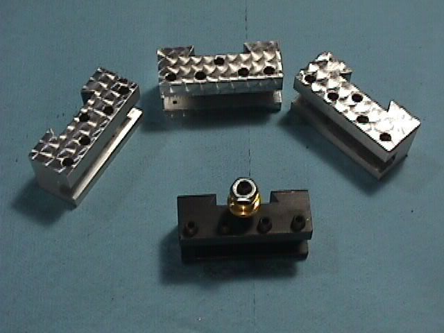
The pic below shows my tools.
Basically, what is shown in the middle of the pic are two plain rods, one of delrin and one ali, these I use with grinding paste or various types of metal polish. They sometimes give fairly inconsistent results, the problem being, the cutting medium breaks down as you are doing the ET, and when you recharge the tip, you get a slightly different depth of cut on the swirl pattern from the previous worn out cutting agent. If you are using a metal polish you can get around this problem by spreading it all over the face, that way you get a new charge every cut. A bit messy if you are using grinding paste.
It was because of that, I moved over to the white things with little shanks on them. These are in fact grinding bits for nimonic steels, and are a hard rubber base with the grinding agent mixed with the rubber. I think these are the same sort of thing that was mentioned in previous posts. These are 8mm and 13mm diameters, but if I want a different size, if you look at the rear of my greasing tool you will see a large grey stick. This is a grinding wheel dresser, but I use it for shaping the ends of the rubber bits to the size I want. There is one shown in front of the greaser. I just pop the bits into my dremel lookalike, and by pressing onto the dressing stick I can make them whatever size I want.
You will notice that my greasing tool now no longer looks like your picture at the top. I only put the ET on there as a bit of humour, and as I said, I do prefer just a plain clean metal, I just wiped it off.
The brass plate in the background is a trial I did a few months ago, to see if the ET could be protected to preserve its looks, as it goes dull, just like any other polished metal. This one is the best preserved one from a few trial samples. I tried varnish, spray on lacquer, but both these have started to show their age. This one however, hasn't tarnished at all, and this is the one that I thought would not work. I actually sprayed it with a product from Letraset, used for sealing the wax rub down letters, to prevent them being damaged. If you don't try it, you don't know if it will work.
I won't go into the technique for doing it as it has already been covered in other peoples posts, especially the one about counting, posted by Gail.

blingkit.jpg


What I have done here is show some of my visually enhanced engines and I will describe why I dressed them up to the stage they are at.

This one shows contrast.
Basically three types.
Metal contrast, the difference between the brass and aluminium.
Surface contrast, the difference between the engine turning and the highly polished parts (also reflecting the ET), this is a very good effect.
Material contrast. To me the best of all, metal against wood. It is a shame I can never get a good standard to my woodwork.

fingers.jpg


These next couple of pics show the difference between a normal engine and one that has been 'worked on' by the bling fairies.
This is a pic of my own designed engine (there is a book on here somewhere that shows exactly how a beginner can make it, dead easy. But I will not tell you where it is, you will have to find it yourself by going thru all the old posts, you will learn a lot on that voyage).

This is the BEFORE.

customa.jpg


This is the AFTER.

This also shows another contrast, paint. Even this Ford Modeena Green shows well on this engine. Bright red or black would have worked just as well, and again would have changed the total look of the engine.
It shows that a bit of ET, material changes, polishing and a few reworked parts can totally change the look of an engine.

custom1.jpg


But I did cheat a bit, I made two of them in parallel, it is just as easy to make two as it is one.

custom5-1.jpg


Here is another brace of my own engines. Same engine, different methods of output.
This is how I really like them, clinical, smooth, well fitting parts and a bit of metal contrast. What more could you want?

6.jpg


This isn't a very good pic, but it does show another way to make a different looking engine from all the rest.
This is a modified Elmer's Mine Engine.
On this one I wanted it to 'look' Victorian.
So the basic plan and dimensions were used, but all sorts were added or changed to give the 'look'. A truly individual engine.

5.jpg


This post has gone a long way from your original 'swirlmark finish'.
But I hope it has shown you that it isn't just the finish, but the way you see how an engine can be made to look individual, just by following a few basic ideas.
Please remember, don't just try to cover bad workmanship up with bling. You will find that well fitting parts and removing all visible machining marks will most probably be all that is required to get an engine looking stunning.

But most of all, enjoy what you are doing.

John
 
Nice post Bog. I see you don't do anything "half way", including the effort made to answer questions. Thank you, its much appreciated.

Up til now, I have not put any effort into "bling" on any of my engines. All of them still show all machining marks. This is perhaps because I like the look of those endmill marks. Some would call the engine it half finished I suppose.

I do love the mirror finish look, but it's so temporary, for me it's hard to justify.

I will take your advice and strive for the contrasts you describe above.

BTW, I am Eric, but usually sign with E. Keeps us Eric's on the boards easily distinguished I guess.

E
 
Engine turning is beautiful, though tedious to do. "Cratex" are the rubberized abrasive sticks to use. You can also use a brush with valve grinding compound or similar grit in a slurry. A stainless steel brush is said to work best. If you use a brush, you need a method of keeping the bristles from expanding when you press down on it. Wrap them with a suitable 0-ring or some heat shrink tubing. Brownell's sells a fancy (and expensive!) gizmo that springloads the brush. It is similar to springloaded engraving tools I've seen and thus easily made by a machinist for a lot less money. Something similar for the Cratex might be nice in a spring-loaded holder too. The spring-load ensures some consistency as well as some ability to track something that isn't entirely flat.

Speaking of Cratex, you can even use a pencil eraser along with some suitable grit in a slurry. These rubberized tips are just so that there is a little but not too much "give".

Some of the nicest examples I've seen of engine turning (other than here, of course!) are on this site:

http://www.cs.ucr.edu/~eamonn/et/et.htm

I have been fascinated to contemplate the possibilities for engine turning with CNC. It would make it possible to apply the swirls in something other than a rectangular grid. Imagine if they spiralled out on a round piece (such as a model engine flywheel!), for example. Or, who will be the first here to mount their rotab with axis parallel to the mill table and do some nice jeweling on an engine cylinder?

Another great example of engine turning may be found on guitars here:

http://www.metalcarver.com/guitar/index.htm

It gives an idea of what can be accomplished with more exotic approaches.

I have played with engine turning myself using the cratex sticks (came across them cheaply on eBay of course!) just enough to see it takes a little practice to make it perfect. It also needs to start from a well polished surface as any tool marks will easily show through the swirl pattern!

Someday soon I'll play a little more with the process. I do like the idea of jeweling non-precision surfaces of one's tools. That and a little cold bluing would really dress things up.

Cheers,

BW

 
Here are two photos of the engine turning tool mentioned early in this thread. I had forgotten that I put a pad on each end so the tool can be used for two different sizes. The photo of the parts shows two springs because I did not have one the right size so I just stacked two. The springs are .36 diameter and the wire diameter is 0.038. The large diameter part is 1/2 diameter and the smaller one is 3/8 diameter. Both are 2 inches long. The slots are 1/8 wide and 3/8 inch long and start 1/4 inch from the end. The hole for the pin is 3/8 inch in from the end. I used a .093 nominal diameter roll pin, but put the hole in the 3/8 rod at .099 which makes it easier to put together and take apart. Unconstrained the pin measures about 0.105. The hole in the 1/2 diameter rod is 3/8 diameter and 1.3 inches deep. I reamed the hole so the 3/8 diameter rod would slide smoothly and buffed the end of the 3/8 rod to form a light chamfer so it would not catch on any tooling marks in the 3/8 bore. A little slop between the parts is OK but they should slide smoothly.

The Scotch-Brite pads are glued on with epoxy. Scratch up the ends of the rods and degrease so the epoxy will stick.

In operation I compress the spring so the pin moves up about 1/2 way in the slot and run the spindle about 2500 RPM. There is nothing sacred about any of this. The dimensions used were so I could use scrap material on hand. I would expect you to do the same. Have fun.
Gail in NM, USA

100_1122_600x450.JPG

100_1123_600x450.JPG
 
Eric,

Sorry about the long winded posts, but I try to make them so that everyone has a chance to understand it.

Getting slightly off post.

If you highly polish a part, and I mean mirror, not just with a rag and metal polish (I use a buffing wheel). You will find that the surface retains its shine almost indefinitely. I can't explain why, maybe someone on here can, maybe it is the waxes used in buffing being embedded into the oxide layer of the material that does it. I have polished steel to an almost chrome finish, and years later they have seen no change.

John
 
When you have a high polish isn't there less actual surface area for oxidation to occur?
Tim
 
John,

As always a very exquisite post by you. I look forward to post like that. I always learn something when you post. Thank you. :bow:

Bernd
 
John,

Are the plans called "Model Marine Engine Requires No Castings" for those two engines you show in your post? If they are, it took me almost a hour to find. :p ;D.

Did find a lot of interesting things along the way though. That Elbow Engine was quite neat. At one point the video made it look like it had almost stopped. One thing members should watch out for when running a lathe or other machine. The cycle from the light can make it look like your machine is stopped. But that is a thread that should be discussed in the "Safety" forum.

Bernd

10:30AM
I studied the prints I downloaded. There are some similarities. I do see where the differences are, such as the reversing valve, separate valve blocks and so forth. Guess I need to do a bit more searching,eh?
 
I do like that tool Gail, and the pattern looks good to me too!
If you don't mind a think I'll make one ;)

John as always your post is very well put and all the pics of your engines ... very nice :) ... ever since I saw your finger engines I have been wondering how you did the pattern on the base... just wasn't going to ask till I could not figure it out! now there are so many explanations I know I can find a good method and do my best to create the finish.

Thank you all for explaining this in great detail ;D

Ralph.
 

Latest posts

Back
Top