Stuart Beam restoration

Home Model Engine Machinist Forum

Help Support Home Model Engine Machinist Forum:

This site may earn a commission from merchant affiliate links, including eBay, Amazon, and others.
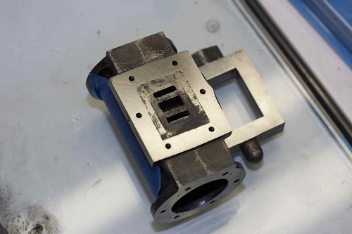
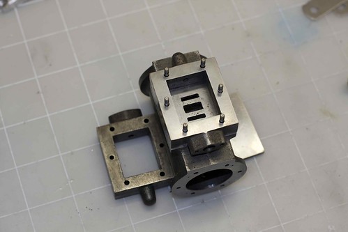
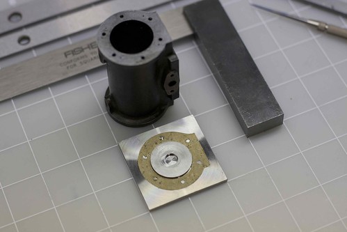
Time to fix the cylinder to the new cylinder base that I machined earlier! This meant spotting the holes through somehow (since I had to match the existing holes in the cylinder).

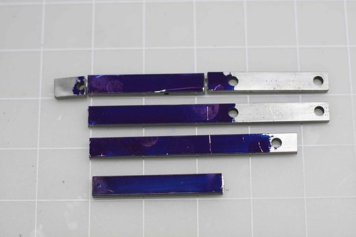
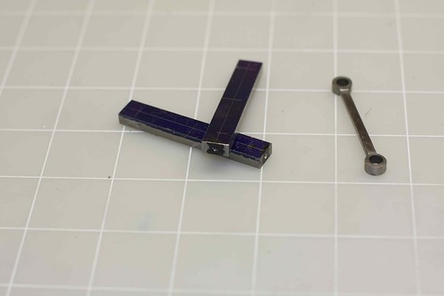
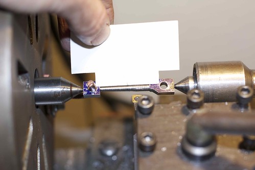
I initially started with annoying little bits of paper:


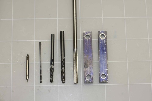
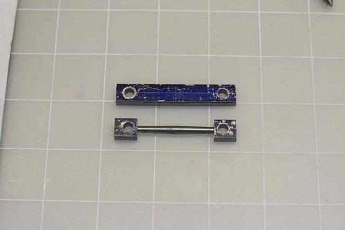
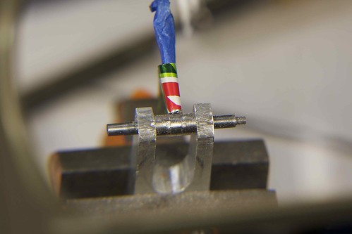
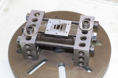
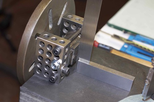
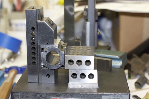
but then had a better idea. I fixed the cylinder up in the vise with a kind of jig that would let me place the base on top repeatably. Then I could just line up on a hole using a drill that was smaller than threaded hole


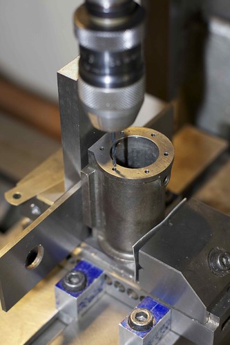
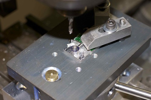
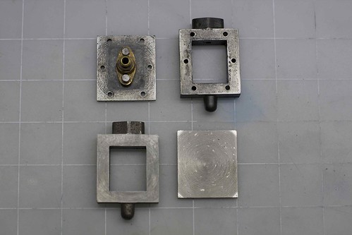
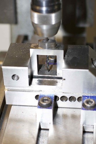
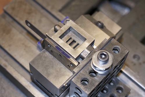
by carefully lowering the drill and looking/listening for interference. Then I just put the cylinder base in place, bottom side up, and, without moving the table, spot-drilled with a center drill:


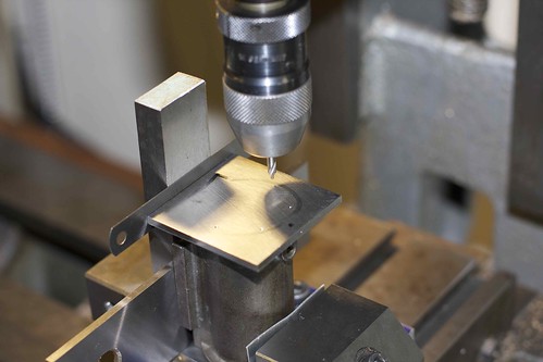
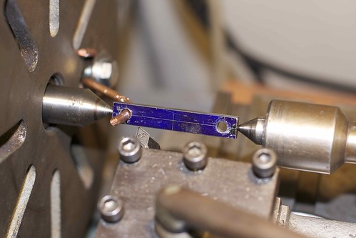
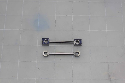
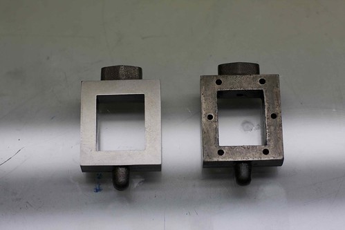
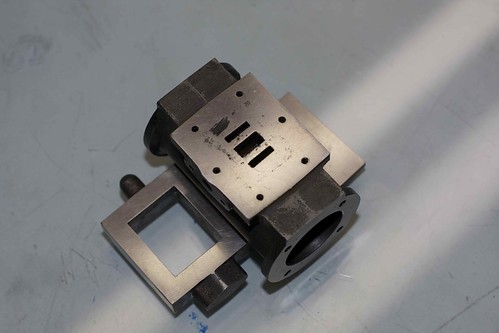
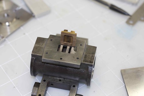
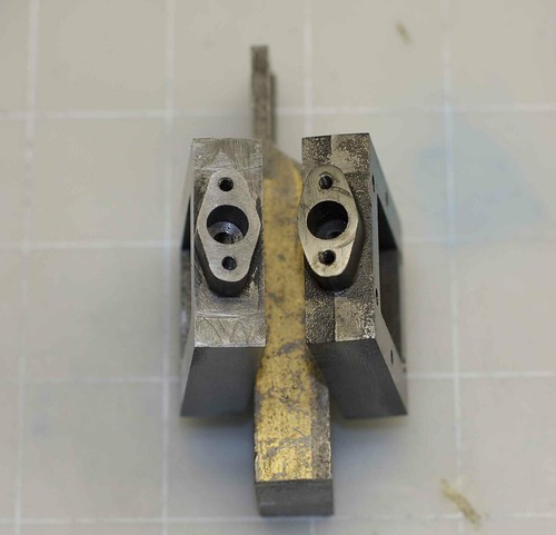
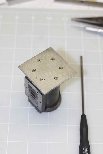
Then I could transfer just the base to the vise, and drill and countersink each hole. Presto, nice fit:


Next will be spotting the holes through from the main casting to the cylinder base, which might be a bit trickier.
 
i just love threads like this :bow: lots of pictures and explanations.
i have been making models and machining things for over 30 years and i learn some thing new every time i log on here.

thanks smfr 8)

chuck
 
Now that's a nice solution. This build is really moving along!
 
You are certainly motoring along with this rebuild, and I like the way you have overcome the various problems encountered. Good sound lateral thinking.
As someone remarked earlier, rebuilding can involve more work than would have been required to do it from scratch, but it’s a nice challenge and you will end up with a very desirable engine.

Les
 
OK, now that I have a turning table (http://www.homemodelenginemachinist.com/index.php?topic=16765), I can show you how I went about making the linkage links. We start with some bar stock:


Actually the top two pieces there are the old entablature arms, which I thought it would be neat to re-use. However, after cutting them to size, I realized that they have screw holes :eek:

I'm making two links here. The bar stock is cut to length accurately for repeatability, and center drilled at the ends, for turning between centers. The length was calculated so that the center drill holes don't hit the metal we want to keep. That's one of the old links on the right.


Now the two holes are center drilled, drilled in steps, and reamed 3/16":


As usual, since the distance between these holes has to be accurate, I do them early in the steps.

I've also learned not to worry about under/over reamers; I just use the exact size. This seems to give a nice snug fit with the drill rod that I'm using for the spindles, but maybe that's because the reamer is pretty new, and is cutting oversize?

Now to turn the fishbellies. We set up between centers, driving via the faceplate. I'm using a bit of thick copper wire as a dog, through one of the holes. Works great!


Now I did a bit of math to work out the correct angle to set the compound rest at; it's around 1.2 degrees (from what I recall), but we'll end up adjusting this a bit. I also made myself a little cardboard template to show me where the middle is, and where I should stop turning:


Once I had a cut that covered half of the turned section, I measured the larger and smaller diameter to see if the difference between them matches what the plans calls for; getting it right required adjusting the angle of the compound rest several times, by small amounts. I'm moving the tool right to left via the compound rest to get the taper, then adjusting the cross-slide to control the final diameter.

Once one half is done, I flipped the part around and do the other half (this is where it's useful to have the bar stock length be accurate). Then came some filing to smooth out the middle, and several grades of emery paper to remove the tool marks (easier to do this now while turning between centers than later!).

Here's one link turned, though it could still use some smoothing:


Now I made use of the rounding table to round the ends:


and we end up with:


The ends still need reducing in thickness, and there's quite a bit of filing to do. I'll clean up all 8 links at the same time (at least until I get bored of filing ;D). 8 links, 16 ends, 32 faces ... that's quite a bit of work :-\
 
NIIIIICE! Good follow thru and great planning and problem solving.

:bow:

Dave
 
Yes! Very nice!

I love your lathe dog smfr, I would have never thought of something so simple!
 
Lots of rather tedious stuff today. Got all 8 links rounded down on the rounding table (some a bit undersize until I realized that I could use a carriage stop to make sure I didn't go too far!), and the 2 new links milled to the right thickness.


(Yeah, I can't count. That's 9. I'm making one extra ;D)

I made myself a fixture to help with filing, and some filing buttons:


The bit of drink can is to prevent the round file from digging into the end of the turned portion, and tape protected the rest. I'm using needle files to do rough cleanup, then various grits of emery paper (220 to 2000) to finish, with a final polish with the Dremel.

2 down, 7 to go, ugh!


Great work! I'm following your restoration with great interest. Thank you for sharing.

I would say you can count just fine. I've been working on 6 simple little Millie steam engines to be given away as Christmas gifts, so that means that I automatically machine 7 of each part. Sometimes I want to try something that may work well or end up ruining the part, or as I'm sure we've all done, simply mess a part up. When you alway make an extra you have something to fall back on.
 
That's a very fine job you are doing Simon. Thm:

The way you are progressing, you are going to be so satisfied with taking something so poorly made and turning into something far far better. Keep up the good work and yes, I love the improvisation on the lathe dog too - I'm getting a little bit old to use the expression but I believe one should say - "very cool" 8)

Regards - Ramon
 
I spent a couple of evening filing the links, and got bored so decided to start on the new valve chest. I bought a new casting from Stuart because the existing one has a hole drilled in the side :-\

The casting was cleaned up with a file, and faced in the 4-jaw chuck on both sides. I started on the valve cover as well, which still needs taking down a little:


I think the corners of the valve cover look different because I don't have enough support behind them in the chuck, and they are flexing under the tool. There also look to be some hard spots in that casting, or maybe the unevenness of the turning is because of something I'm doing?

The valve chest after some lapping on the plate glass:


That's the easy part! I have to transfer the holes from the cylinder itself on this one, and drill for the valve rod etc.
 
I've been thinking that I need to clean up the valve surface on the cylinder, since it's pretty messy:


It has some bad pitting. I also noticed that the valve surface wasn't perpendicular to the cylinder base:


so decided to take a pass over it in the lathe. That sounds like a good job for the faceplate! I don't have an angle plate, but figured that a couple of 1-2-3 blocks would hold it quite nicely:


I used a square with the blocks on the edge of the surface plate to true up the valve surface:


and took off maybe 0.01" on the lathe. After some cleanup, it looks like this. I took the Dremel with a wire wheel to the rusty bits, and that cleaned out a ton of rust, leaving a bit of a crater :eek:


I was a bit worried about taking more off. I hope that massive rusty hole isn't going to be an issue, since the valve just about clears it:


That's the valve face of the cylinder taken care of!
 
Now back to the valve chest. After lapping the faces, I trued it up in the vise, and drilled for the valve rod:


Ideally it would have been rotated 90deg in the vise for better clamping, but I need to see when the drill hit the bottom. The top hole gets drilled and reamed for 1/8", and the valve rod requires a 3/32" locating hole in the bottom. I used the larger drill to make a small face in the bottom surface so that the thinner drill didn't wander. Luckily I had a 3/32" jobber drill lying around, since my stubbies wouldn't reach that far!

Here's the bottom of the valve chest after making the counterbore for stuffing and the gland, with two 7BA holes drilled and tapped for the gland cover. New on the left, old on the right.


I have to clean up those messy file marks. I'm not sure whether to smooth off the entire valve chest surface, or leave it looking like a casting.

Now I have to transfer the holes from the cylinder. I did this like before; set up the cylinder in the vise, here truing it up with the trusty 1-2-3 blocks:


then adding various bits of packing so that I can repeatably position the valve chest:


I then locate a hole in the cylinder valve face using a drill slightly smaller than the hole size (without the valve chest in place), switch to a small center drill, put the valve chest in place then spot-drill the valve chest. After spotting all 6 holes, I remove the cylinder from the vise, put the valve chest in, and drill those holes through.

Here we are, with studs in place, showing that the hole transfer was a success! I even used a slightly smaller clearance drill than the original builder ;D


Now I can transfer the holes to the valve cover in the conventional way.
 
Got most of the valve rod done today. I used 303 stainless, so hopefully it won't rot like the old one ;D


Not sure what the original builder was thinking; his rod is about 1/8" too short!

I made the little valve thingy out of SS too; just need to make it slightly looser in the valve so that the valve floats nicely.
 
Some very ingenious setup work for machining the cylinder. Great work on the restoration.
gbritnell
 
You're doing a great job on the restoration Simon :bow:

Just a thought... If the "crater" on the valve face is a problem, you could possibly make a separate valve plate from thin brass plate that you can sandwich between the valve chest and the cylinder. A coating of gasket sealer between the plate and the cylinder block should seal it well.

Kind regards, Arnold
 
Comming along well Simon,

Arnolds suggestion for a seperate plate is a sound one, for many engines this was the prefered way. Also for the valve stem you can get hydrolic loc from the extention bit that the origonal builder made short, especialy if its a very good fit, the solution is to put a small flat along it, this lets the air/oil out and solves the problem.

Stew

 
Arnold: thanks for the suggestion of the valve plate! I hadn't thought of that. I'll see whether the crater is a real issue once things are together. I was also thinking perhaps some JB Weld to fill the hole?

Stew: good point about hydraulic lock, I'll file a small flat on that part.
 
Just noticed an annoying boo-boo. I had the valve chest upside-down when I was spotting the holes through :mad: For some reason I thought the valve rod entered at the bottom.

Luckily the holes are symmetrical enough that I can fit it the other way, but it's not quite straight. I'll have to enlarge the holes to give myself a bit more play.
 
smfr said:
I had the valve chest upside-down

Can't you turn the cylinder the other way around ?

Either stating the obvious or another dumb idea - 2c

Ken
 

Latest posts

Back
Top