Stuart Beam restoration

Home Model Engine Machinist Forum

Help Support Home Model Engine Machinist Forum:

This site may earn a commission from merchant affiliate links, including eBay, Amazon, and others.

smfr

Project of the Month Winner!!!
Project of the Month Winner
Joined
Oct 29, 2011
Messages
287
Reaction score
2
Hi folks

I've been working on restoring a Stuart Beam, and thought that I should put up some photos. I bought this engine along with a 501 boiler on eBay in 2010, before I even had a lathe, and fixing it up was a good excuse to get one ;D

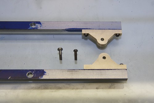
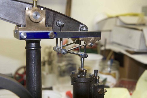
The engine had its share of problems, a really ugly paint job, and some odd modifications. It had obviously seen quite a bit of use, with some notable wear on the conrod big end, a fairly loud knocking when running, and a lot of looseness in the parallel linkage.

My goal is to get it back to a nice quality, smooth-running engine. This is my first real steam project with the lathe (you can see my setup here: http://www.homemodelenginemachinist.com/index.php?topic=16417.msg167565#msg167565).

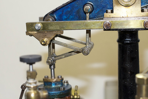
Here's the engine in its original state:

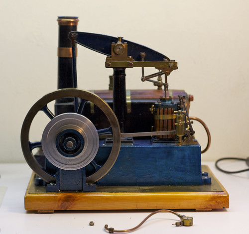
Stuart Beam by smfr123, on Flickr
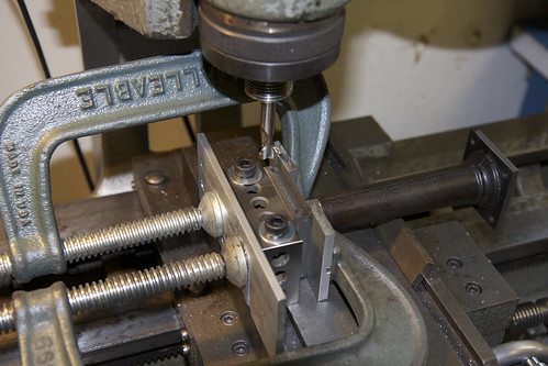
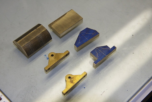
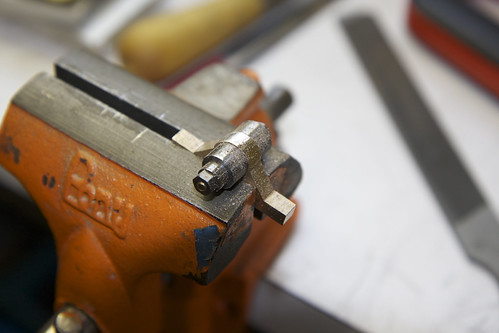
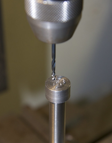
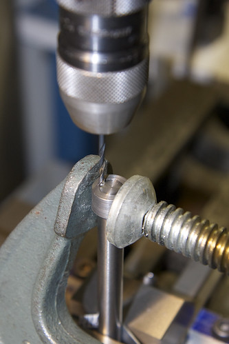
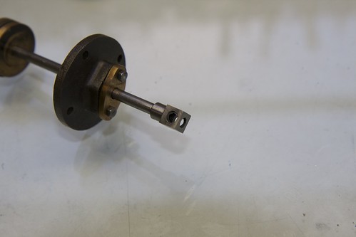
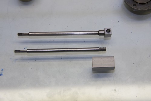
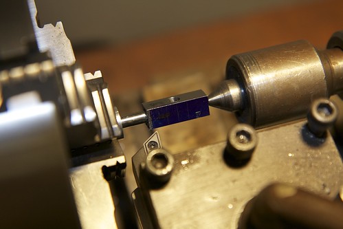
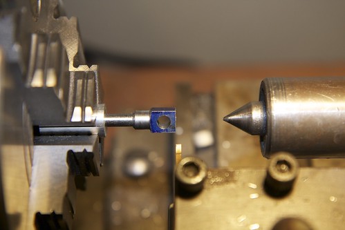
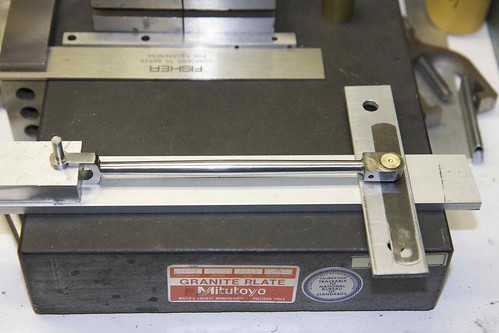
 
Some more pre-restoration pics:

No fish-bellying on the linkage:


The previous owner loved brass! So much so that they put thin brass strips over the entablature arms:


They did something awful to the steam chest: drilled a hole in the side for the displacement lubricator, which forced them to set the valve mechanism at a weird angle:


Oil cups soldered onto the main bearings:


Another bit of brass covering the flywheel, and aluminum disc press-fitted onto the pulley:

 
Step 1: paint stripping.

I don't have any pics of the stripping process. Basically I smeared the painted parts in Citristrip http://www.citristrip.com/, put them in a ziplock bag overnight, then cleaned everything off the next day.

After stripping, I put it back together. Looks better already!


Only then did I noticed how loose it was, so it got pushed to the back of the workbench, pending lathe availability.
 
That citristrip is great stuff. I used it on my SB 9a and it was once and done.

You didn't like the candy apple blue paint??

Can't wait to see it done.
 
Steps 2-N

Lots of work represented in this picture:


I decided to machine new parts for the parallel linkage, since the existing ones were rather sloppy, and not very pretty.

There are eight parallel links, machined from CRS bar. I first drilled and reamed the holes, then turned between centers, using the crosslide to get the fish belly taper. Then the ends were rounded off using a rounding fixture. They still need final filing and trimming to thickness, and I think I'll remake a couple of them; you can see a few boo-boos if you look carefully.

On the right are the various linkage spindles, make from 3/16 drill rod, and the linkage spacers. In the lower right is the new crankpin. This needs a slot cut in the head to allow it to be tightened up.

On the left is the original connecting rod, but I added bronze bushings to both ends to tighten things up. The hole in the big end was actually oval from wear. I've also made bushings for the beam, but have not yet drilled and reamed out the holes in the beam to fit them yet in the photo.
 
Now for some work on the column. I noticed that the arms weren't parallel with the base, so had to correct that in two ways. First, I enlarged the bolt holes in the bottom of the column to allow for some adjustment. Second, I re-machined the top of the column. I also skimmed the top and bottom of the column between centers (via the original punch marks!) to correct the fact that it was too tall.

Here I'm tidying up the base of the column (it wasn't machined square by the original builder).


Now it's time to clean up where the arms attach. Note the 1-2-3 block used as an angle plate.


This leaves the arms about 10 thou closer together than they should be, but I can take that up in the linkage spacers.
 
Now for some new radius link bearings. The hole was off on the originals. I cut up some bronze bar stock using a slitting saw, and discovered that bronze sure does like to squirm around in the vise when being cut! See the messy cuts on the upper right piece. Some paper between the bronze and the jaws fixed that though.


The originals are the two on the left; my new ones on the right. They started out oddly shaped because I got two out of one slice by placing them diagonally. The lower right one shows another boo-boo; I was a bit eager with the rough milling. Oh well, time to use the extra piece of bronze!

Getting closer now, just need some filing:


I turned some filing buttons, and used them to shape the radius:


My first use of filing buttons!
 
The next adventure was to make a new crankshaft. I had some 7/16 drill rod, reduced one end to fit the crank (actually this took two tries :) ), and then wondered how to fit the pin (which was used on the old crank). I knew there was no way I could drill the pin hold with the crank in place; the drill would just wander toward the crank. So I turned a sacrificial collar, lower left.


With the collar in place, fitting tightly, I started to drill:


Darn, broken bit :mad: The collar rotated while being drilled, catching the drill. Let's try again:


Much better! Another option would have been to Loctite the collar on, I guess.

Now with the crank in place, I drilled a slightly larger hole to clean up the mess from the broken drill:


Turned a pin to fit the hole, and knocked it in:


After some cleanup, not too bad!


Good stuff, I like rebuilds your doing some fine work there. Keep it coming.
Brock
 

A restoration can sometimes be more difficult than building the original. Your setups and machining methods are spot on, and
your observations and diagnostics of part wear and misalignment should be a point well taken by anyone attempting similar work.
It's a pleasure to see your nice work and I'll be watching for more.

Regards,
Mike
 
I got the radial link bearings done today (other than the final polishing). Here I'm taking them down to the final 3/8" thickness:


For drilling the attachment holes, I taped them to the arms:


The tape both kept them in the right place, and took up any difference between the bearing and arm thicknesses so that they'd both be secure in the vise.

Some careful hole drilling:


and after a bit of clearance drilling, and tapping the arms, we're done. I did make one minor error, which was to choose too large a drill for the clearance holes in one bearing. I was reading the drill size table upside-down :D


I'm not sure if those are the right screws, but it's what was in place before.
 
Now it's time for the piston rod. I debated whether to make a new one, but the old crosshead had an ugly hole in the top:


and there was no way I was going to be able to unscrew that crosshead from the piston rod without damaging it. The old rod is also slightly undersize, and is not stainless steel. Here's what the whole rod, piston and cylinder cover look like:


So, I started with some 3/16" drill rod, and made a collet out of aluminum so that I could hold it in the chuck without marking the rod.. I turned the piston end, and threaded. Here's my handy home-made tailstock die holder:


The top end gets a 2BA thread, to fit into the crosshead:


I decided to attach the crosshead to the piston rod before drilling the other hole and bringing it to size so that I could ensure that things were square to the piston rod. The chunk of CRS for the crosshead was drilled and tapped, with a bit of messing around with the depths, since it felt loose even when screwed in. However, once I screwed it on tight it was fine, and Loctite helped ;D

I made a little fixture to keep the piston rod horizontal in the vice while I machined the sides of the crosshead:


then drilled and reamed for the linkage hole:


You can see that I'm too lazy to remove the layout dye from my vise clamps :)

Here's my ghetto DRI when I need to move the carriage accurately:


It's a micrometer that I knocked on to the floor, and bent the tips. It's still good for this purpose though 8)

OK, now we're here:


Time to chuck it up again (in the collet, centered in the 4-jaw) to turn the shoulder, and bring to length:


And this is when disaster struck. I had done the shoulder with a nice bevel, and then thought that it would be smart to use the parting tool to cut off the top. Big mistake! As the tool broke through, it bent the top of the piston rod; not a huge amount, but enough to write off the part
:'(


Oh well, now I have an excuse to re-make it using precision-ground SS rod, which is what I should have used for the piston rod in the first place :)
 
I had a couple of hours this evening, and after yesterday's piston rod disaster, decided to do a dry run fitting the new parts together. Here's the parallel linkage, with newly machined parts:


It's a real jigsaw puzzle to put together. But once assembled, I was very pleased to find very little play in the mechanism: it's a bit stiff, but I think that's good. It should run in nicely. There's a bit of play in the piston rod, but I'm pretty sure that's play from the piston rings moving in their groove (I plan to make a new piston).

There are more serious problems at the crank end. As the crank rotates around it's forcing the crankshaft to wiggle, and I can't insert the spindle through the little end of the connection rod and the beam because of misalignment. I'm guessing that something is out of whack with the crank or the connecting rod. I can make a new conrod, and maybe drill out the crank pin hole in the crank, fit a bushing, and drill it straight.
 
That is coming along very nicely indeed, it is looking and moving as it really should.

I used to do a fair amount of restorations for other people, and I just couldn't believe how badly some people could treat a very expensive set of castings.
A lot of the time, they were so badly treated, like the ones you have, you have to start from scratch, attempting to put them right.

People seem to think it is just a matter of buying a set of castings and assembling it. Nothing is further from the truth. You really need to get some experience under your belt first, otherwise you can end up getting someone else to put it right for you when it doesn't run.

It should be a wonderful engine when you are finished.


John
 
very nice work, and wonderful writeup!
hats off, Sir.

take care,

tom in MA
 
I managed a bit more work on the crank/conrod to try and relieve some of the stiffness there. After messing around with squares and such:


I decided that the big end was not drilled square originally, so I made a new bronze bushing (with a dimple for centering) and pushed it in:


so that I could then drill and ream it in-place.

That required making a fixture that would hold the conrod in the correct alignment: what's important is that the holes in each end are aligned. A couple of bits of Al were pressed into service. I milled a slot in one:


then superglued them together, and drilled and reamed a 3/16 hole for a pin that would go through the little end of the conrod, thus ensuring that the rod is aligned.


I placed some packing under the big end to make sure the rod was horizontal. Then I drilled and reamed the bushing on the mill (I don't have any pictures of that, because I'm embarrassed about my crappy clamping job ;D). I also found that bronze loves to grab drill bits if you do step drilling, but with some careful drilling, and a 1/4" "over" reamer, managed to get a nice hole.

After all this, things are much better aligned when I hook up the conrod, so progress has been made!
 
You can stone the drill so it won't grab in brass or bronze. ?

I'll show you if you like.....

Dave
 
Sure, I'd love to see how to "stone" the drill to avoid the problem with bronze. I've also seen others just drill the hole in one go, which seems do-able in bronze. Or maybe just a small pilot hole, then drill to size.

Does stoning the bit dull it for other tasks?
 

Being able to "stone" the drill is a useful skill when machining brass or bronze. It's done by changing the rake
angle of the cutting edge to zero degrees or even a few degrees negative in some cases. Just take a medium
oil stone and place it on the entire cutting edge aligned with the axis of the drill. A few strokes will produce a
small flat about .01 to .015 in. wide. Repeat on the other side. When ground like this the drill won't grab even
when breaking through. This trick also works to stop chatter on some other materials. As the new angle is quite
small, the drill is easily resharpened for standard use.
 

Latest posts

Back
Top