
You are using an out of date browser. It may not display this or other websites correctly.
You should upgrade or use an alternative browser.
You should upgrade or use an alternative browser.
Stuart Beam restoration
- Thread starter smfr
- Start date


Help Support Home Model Engine Machinist Forum:
This site may earn a commission from merchant affiliate
links, including eBay, Amazon, and others.
- Joined
- Oct 29, 2011
- Messages
- 287
- Reaction score
- 2
Patrik said:Really like your restoration! Coming along nicely!
What's the size of it? I'm having a hard time comparing.
Will you do another piston rod?
I'll be following along!
I'm glad you're finding it interesting!
It's a 1" bore, 2" stroke engine. I received some 3/16" precision-ground SS yesterday, so I'll be using that for a new piston rod. I do need to get some 1/4" steel plate to make a new base for the piston though; the screw holes are off, and the piston base doesn't sit flat on the main casting.
- Joined
- Oct 29, 2011
- Messages
- 287
- Reaction score
- 2
I made quite a bit of progress today. I started with a new cylinder base. I chose to make a new one because I want to adjust the position of the cylinder relative to the column, and because the holes for the countersunk screws that go into the cylinder are not aligned correctly, causing those screws to stand proud, which in turn means that the cylinder base doesn't sit well on the main casting. I also wanted something that looked a bit prettier ")
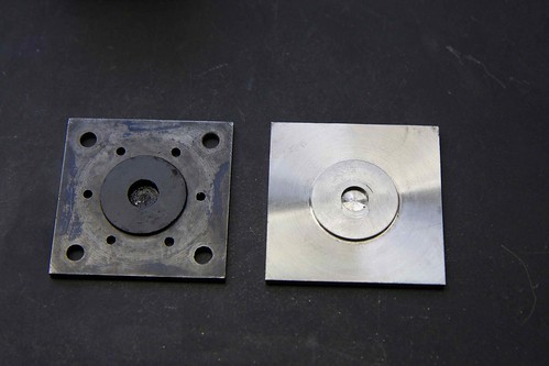
Guess which is which! I used some 1/4" steel plate (not sure what kind; I got it at the Aluminum Rem Center in Santa Clara, CA), milled to a fairly accurate 2" x 2". I then started to fix this in the 4-jaw, thus marring the nice clean sides before realizing that I needed to turn in from the edge.
I moved it back to the mill, centered it up, and used a 5/16" end mill to cut the central depression (that allows room for the nut on the end of the piston rod at bottom dead center). That provides a footing for a stub mandrel; I turned the end of of a bit of scrap drill rod to 5/16", center-drilled into the other end, and used it in the tailstock to push the plate against the chuck (using a handy chuck spider that I made a while back):
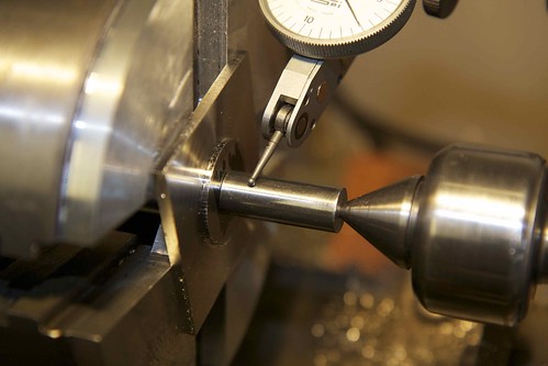
Since the mandrel is a snug fit, I used it to indicate for accurate centering.
Because it's just pushed against the chuck, you have to take light cuts (ask me how I know). Maybe some paper behind it would have helped. It's also a pain to turn down to size to fit the cylinder, since you have to remove it for test fitting, and then re-center it every time, so I went by the calipers most of the time.
I left the problem of locating all the holes to another day...
Guess which is which! I used some 1/4" steel plate (not sure what kind; I got it at the Aluminum Rem Center in Santa Clara, CA), milled to a fairly accurate 2" x 2". I then started to fix this in the 4-jaw, thus marring the nice clean sides
before realizing that I needed to turn in from the edge.I moved it back to the mill, centered it up, and used a 5/16" end mill to cut the central depression (that allows room for the nut on the end of the piston rod at bottom dead center). That provides a footing for a stub mandrel; I turned the end of of a bit of scrap drill rod to 5/16", center-drilled into the other end, and used it in the tailstock to push the plate against the chuck (using a handy chuck spider that I made a while back):
Since the mandrel is a snug fit, I used it to indicate for accurate centering.
Because it's just pushed against the chuck, you have to take light cuts (ask me how I know). Maybe some paper behind it would have helped. It's also a pain to turn down to size to fit the cylinder, since you have to remove it for test fitting, and then re-center it every time, so I went by the calipers most of the time.
I left the problem of locating all the holes to another day...
- Joined
- Oct 29, 2011
- Messages
- 287
- Reaction score
- 2
I also smartened up the cylinder head today; the sides and top were not machined at all before. Here's the result:
It's an improvement in that it gives the bolts a flat surface to bear down on, but feels perhaps slightly too blingy for this model. We'll see once everything is together.
It's an improvement in that it gives the bolts a flat surface to bear down on, but feels perhaps slightly too blingy for this model. We'll see once everything is together.
- Joined
- Oct 29, 2011
- Messages
- 287
- Reaction score
- 2
OK, it was time for a second try making the piston (see earlier messages for the fate of the first one ;D).
I bought a 6ft length of precision-ground 3/16" stainless steel from McMaster-Carr for this, but the entire rod came with a gentle curve so I went back using drill rod. Machining this part was uneventful, though I was careful to not make the 1/4" threaded portion on the top end too long.
I attempted to re-use the top piece I made before:
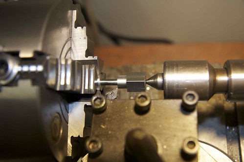
but when screwed onto the new rod, it was obviously misaligned. This vindicates my technique of machining this piece after attaching it to the rod. So I started with a new chunk of CRS (on the right in the picture).
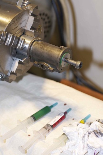
It was faced, center-drilled, then drilled and tapped 2BA. I was careful to not drill and tap too deep, because the piston rod has to tighten up to the right length. I then screwed in the rod with Loctite:
I'm wondering now if I messed up here. I recall reading that this needs to remain adjustable to tweak the piston travel :'(
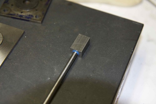
Anyhoo, here I am turning down the neck of the piston rod:
where I went a wee bit over, but this isn't a critical dimension. And here we are after two sides of the head have been milled down:
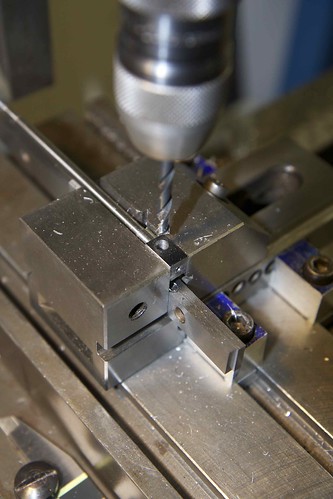
After milling the head to size, it's time to locate, drill and ream the 3/16" hole. I used my trusty vernier height gauge, with the piston standing upright on a spacer on the surface plate, and measure from the top of the piston to where the hole should be. I'm gradually learning what the height gauge is good for (and how to read the vernier scale!). Now into the vise again (with a fixture to keep the rod horizontal), for drilling and reaming:
This time I took the head down to size by holding it in the 4-jaw (with some Coke can packing to avoid marring). No parting off this time!
Now we can have some fun making the piston! I started with a length of bronze (that's the old piston in front):

and here we are after some machining:
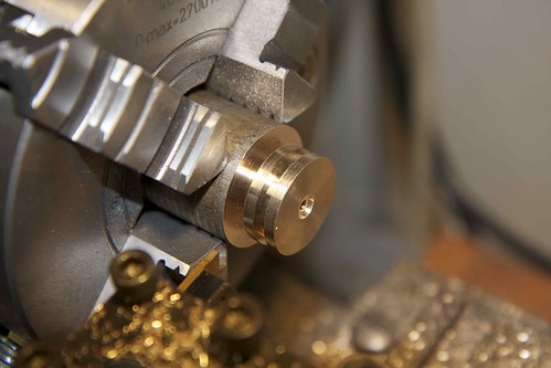
The central depression was made with a 5/16" end mill in a chuck the tailstock, and I've drilled and reamed the center 1/8". Unlike the old piston, the groove for the piston rings is a snug 1/8". I'm leaving it oversize for now, to do the final tweaking when it's fixed to the rod.
That leaves me with the new piston parts:
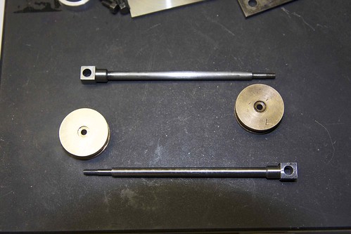
(old above, new below).
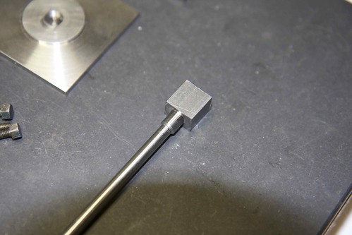
Here the rod is protected with tape while I cleaned up the head with a file.. I'm also test-fitting a 3/16" spindle with a spacer. I was pondering rounding off the top to match the radius, but left it square for now.
So, almost done with the piston (new above, old below):
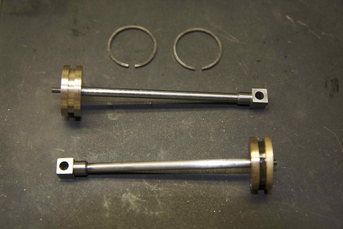
I just hope that the length is right 8)
I bought a 6ft length of precision-ground 3/16" stainless steel from McMaster-Carr for this, but the entire rod came with a gentle curve
so I went back using drill rod. Machining this part was uneventful, though I was careful to not make the 1/4" threaded portion on the top end too long.I attempted to re-use the top piece I made before:
but when screwed onto the new rod, it was obviously misaligned. This vindicates my technique of machining this piece after attaching it to the rod. So I started with a new chunk of CRS (on the right in the picture).
It was faced, center-drilled, then drilled and tapped 2BA. I was careful to not drill and tap too deep, because the piston rod has to tighten up to the right length. I then screwed in the rod with Loctite:
I'm wondering now if I messed up here. I recall reading that this needs to remain adjustable to tweak the piston travel :'(
Anyhoo, here I am turning down the neck of the piston rod:
where I went a wee bit over, but this isn't a critical dimension. And here we are after two sides of the head have been milled down:
After milling the head to size, it's time to locate, drill and ream the 3/16" hole. I used my trusty vernier height gauge, with the piston standing upright on a spacer on the surface plate, and measure from the top of the piston to where the hole should be. I'm gradually learning what the height gauge is good for (and how to read the vernier scale!). Now into the vise again (with a fixture to keep the rod horizontal), for drilling and reaming:
This time I took the head down to size by holding it in the 4-jaw (with some Coke can packing to avoid marring). No parting off this time!
Now we can have some fun making the piston! I started with a length of bronze (that's the old piston in front):
and here we are after some machining:
The central depression was made with a 5/16" end mill in a chuck the tailstock, and I've drilled and reamed the center 1/8". Unlike the old piston, the groove for the piston rings is a snug 1/8". I'm leaving it oversize for now, to do the final tweaking when it's fixed to the rod.
That leaves me with the new piston parts:
(old above, new below).
Here the rod is protected with tape while I cleaned up the head with a file.. I'm also test-fitting a 3/16" spindle with a spacer. I was pondering rounding off the top to match the radius, but left it square for now.
So, almost done with the piston (new above, old below):
I just hope that the length is right 8)
- Joined
- Oct 29, 2011
- Messages
- 287
- Reaction score
- 2
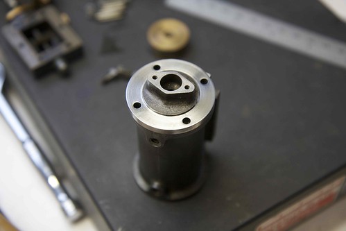
One final picture for today. This shows the old valve chest and parts at the top:
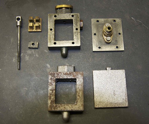
There are a couple of interesting (i.e. bad!) things to note. First, the valve rod is really worn and corroded, so I'll be replacing that. Second, some fool drilled a hole in the side of the valve chest to fit a displacement lubricator, which is crazy because it interferes with the valve linkage. I temporarily plugged it with a brass bolt, but wanted a better long term fix. So I ordered a new valve chest and cover from Stuart Models (lower in the picture), and will be machining those later.
There are a couple of interesting (i.e. bad!) things to note. First, the valve rod is really worn and corroded, so I'll be replacing that. Second, some fool drilled a hole in the side of the valve chest to fit a displacement lubricator, which is crazy because it interferes with the valve linkage. I temporarily plugged it with a brass bolt, but wanted a better long term fix. So I ordered a new valve chest and cover from Stuart Models (lower in the picture), and will be machining those later.
Great job! :bow:
I learn more about machining and steam engines in general by watching rebuilds like this.
It looks so easy watching/reading someone doing it right first time but it doesn't show the pitfalls.
Many thanks for posting.
Andy
I learn more about machining and steam engines in general by watching rebuilds like this.
It looks so easy watching/reading someone doing it right first time but it doesn't show the pitfalls.
Many thanks for posting.
Andy
First, the valve rod is really worn and corroded
In fact, it is for that reason you use stainless as much as possible.
You will find that the silver steel (drill rod) you are using will very quickly succumb to rust as well.
I have seen operational steam engines in model boats completely ruined by corrosion because the owner stored them damp when put away for the winter, rather than just inhibiting them with a few drops of oil.
Coming along really well now.
John
- Joined
- Oct 29, 2011
- Messages
- 287
- Reaction score
- 2
After being away for a few days, I got some time in the garage yesterday, and decided to clean up the cylinder bore a little. It's pretty corroded at one end:
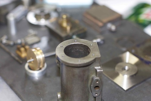
probably from sitting with moisture after being used with steam. To take off the pitting, I think I'd have to bore it out another few thou or so (after setting it up absolutely straight), and that sounded tricky. So I decided just to lap it to smooth out the rest of the bore. I think most of the pitting it outside the piston travel anyway.
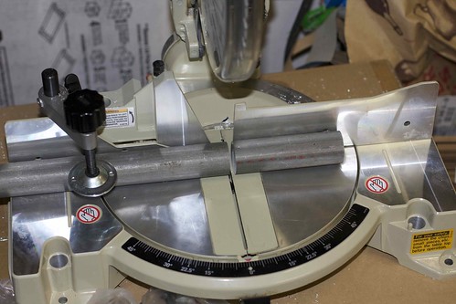
So I made a lap from some Al rod (another estate sale find!). I cut off a length of rod on the chop saw:
and turned to just under 1", drilled and tapped for M8 1.25, then used the slitting saw on it:
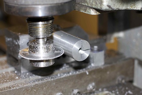
(if you look carefully you can see I'm not quite on the centerline, despite measuring and using dials to get there )
Now I can adjust the lap by screwing in an M8 bolt. Here's the cylinder in place:
You can see the three grades of lapping paste. The lathe was run at low speed, and the cylinder is held by hand (carefully!) and moved up and down the lap, reversing it every so often.
I was trying to figure out how to make the lap so that it expands in the center, rather than at the end; I wasn't able to drill deep enough to have the end of the screw thread further in. Having the lap expand in the middle means that the cylinder is less likely to be misaligned as you move it back and forth (which would result in a bell-mouthed bore).
Anyway, I lapped off about a thou or so, which smoothed out some of the roughness. No after pics, alas.
I then mounted the piston on the piston rod, and carefully turned it down to size. Not carefully enough, apparently, as it ended up a sloppy fit
So I made another piston from bronze, and brought that one down to size with emery paper. Apparently I was too aggressive there as well, because that one ended up a bit sloppy too, but close enough for now. With the piston rings fitted, it feels quite snug. I seem to recall reading that you needed some room for piston expansion if it's going to be run on steam anyway.
probably from sitting with moisture after being used with steam. To take off the pitting, I think I'd have to bore it out another few thou or so (after setting it up absolutely straight), and that sounded tricky. So I decided just to lap it to smooth out the rest of the bore. I think most of the pitting it outside the piston travel anyway.
So I made a lap from some Al rod (another estate sale find!). I cut off a length of rod on the chop saw:
and turned to just under 1", drilled and tapped for M8 1.25, then used the slitting saw on it:
(if you look carefully you can see I'm not quite on the centerline, despite measuring and using dials to get there
)Now I can adjust the lap by screwing in an M8 bolt. Here's the cylinder in place:
You can see the three grades of lapping paste. The lathe was run at low speed, and the cylinder is held by hand (carefully!) and moved up and down the lap, reversing it every so often.
I was trying to figure out how to make the lap so that it expands in the center, rather than at the end; I wasn't able to drill deep enough to have the end of the screw thread further in. Having the lap expand in the middle means that the cylinder is less likely to be misaligned as you move it back and forth (which would result in a bell-mouthed bore).
Anyway, I lapped off about a thou or so, which smoothed out some of the roughness. No after pics, alas.
I then mounted the piston on the piston rod, and carefully turned it down to size. Not carefully enough, apparently, as it ended up a sloppy fit
So I made another piston from bronze, and brought that one down to size with emery paper. Apparently I was too aggressive there as well, because that one ended up a bit sloppy too, but close enough for now. With the piston rings fitted, it feels quite snug. I seem to recall reading that you needed some room for piston expansion if it's going to be run on steam anyway.
- Joined
- Oct 29, 2011
- Messages
- 287
- Reaction score
- 2
ShedBoy said:Really nice work Simon, looking forward to seeing this one going again. Did it come with a boiler?
Hi Brock, thanks for the comments! It did come with a boiler, a Stuart 501. I've cleaned that up already, but I think I need to solder in a new nipple, since the threads on one of the existing ones are worn, which is worrisome. I haven't done any boiler stuff yet.
- Joined
- Oct 29, 2011
- Messages
- 287
- Reaction score
- 2
my65pan said:Very nice work! I'm just getting started in these little engines, but a restoration like this looks like something I'd really enjoy doing. Do many old engines come up for sale on e-bay or elsewhere?
They do show up on eBay from time to time, but it's buyer beware. It's pretty much impossible to tell how well the original machining was done, so you might get something nice and smooth, or you might get a sloppy mess!
- Joined
- Oct 29, 2011
- Messages
- 287
- Reaction score
- 2
I've been trying to find the source of some tightness at the crank end, and spent much of today chasing a couple of theories.
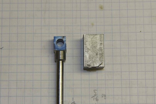
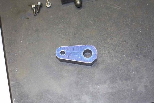
My first theory was that the holes in the crank were misaligned, causing binding as the crankshaft rotates. To test this, I made a new crank, starting with a chunk cut from an old toolholder, milled to size and marked out:
I located the first hole, drilled and reamed, and then used the dials to move over exactly an inch for the second hole:

I've learned that it's best to take care of the precision aspects of a part early on, while it's easy to hold; the shaping can come later.
After some rough milling, it looked like this:
and here we are in the 4-jaw after turning the larger boss.

It was tricky to get between the bosses; if I had a rotary table, I think I'd use it for this. I just wanted to get far enough to do a test fit, so turned down some spare 7/16" drill rod to act as a crankshaft and did a press-fit. Here are test and original cranks next to each other:

You can see my attempts at turning out the space between the bosses. It's hard to get tools in there, without dinging the bosses (which I managed to do).
Anyway, after putting everything back together, this new crank didn't seem to make things any better, so I guess the problem isn't in the crank!
My first theory was that the holes in the crank were misaligned, causing binding as the crankshaft rotates. To test this, I made a new crank, starting with a chunk cut from an old toolholder, milled to size and marked out:
I located the first hole, drilled and reamed, and then used the dials to move over exactly an inch for the second hole:
I've learned that it's best to take care of the precision aspects of a part early on, while it's easy to hold; the shaping can come later.
After some rough milling, it looked like this:
and here we are in the 4-jaw after turning the larger boss.
It was tricky to get between the bosses; if I had a rotary table, I think I'd use it for this. I just wanted to get far enough to do a test fit, so turned down some spare 7/16" drill rod to act as a crankshaft and did a press-fit. Here are test and original cranks next to each other:
You can see my attempts at turning out the space between the bosses. It's hard to get tools in there, without dinging the bosses (which I managed to do).
Anyway, after putting everything back together, this new crank didn't seem to make things any better, so I guess the problem isn't in the crank!
- Joined
- Oct 29, 2011
- Messages
- 287
- Reaction score
- 2
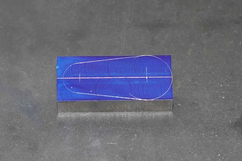
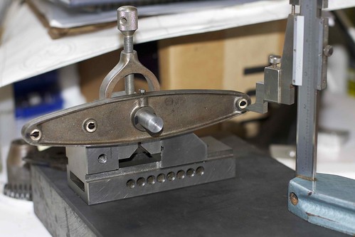
So, next theory. The holes in the beam are misaligned. Certainly the spindle hole at the crank end seems a bit off:
so I spent a bit of time on the surface plate, trying to figure out if there really was a problem:
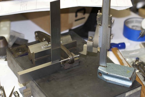
and decided that there was. I suspect what happened is that the beam is slightly twisted, and doesn't lie flat. The beam was clamped down for drilling, but when released, it sprung back, resulting in non-parallel holes.
So I pushed out the bronze bushings that I'd made earlier, and turned new, solid bushings, which I plan to drill in situ. Since I was doing one, I decided to do the other two spindle bushings too, and re-locate the holes as well as straightening them. With the bushes fixed in place with Loctite, I then tried to figure out how to mark things up:

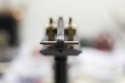
The important thing is that the spindle holes are aligned with the center of the main spindle, so here the beam rests on V-blocks while I try to find a centerline through the center of the main spindle, to mark on the bushings. I'll use this to align the part on the mill.
Likewise, I want to ensure that the spindle holes are drilled parallel to the main spindle, so I think I'll use a setup something like this:
where the main spindle is held in a V-block on its side. That's not my final setup; way too much overhang on the ends ;D
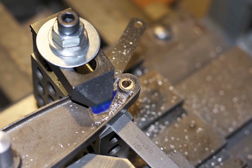
It's interesting how far off the centerline is from the original holes:
so the original builder didn't seem to be very accurate with the beam. I just hope none of my holes hit the edge of the bushing!
So tomorrow I'll have a go and fixing this down (without twisting!) and drilling. Hey, at least I can push out the bushings and make new ones if I mess up!
so I spent a bit of time on the surface plate, trying to figure out if there really was a problem:
and decided that there was. I suspect what happened is that the beam is slightly twisted, and doesn't lie flat. The beam was clamped down for drilling, but when released, it sprung back, resulting in non-parallel holes.
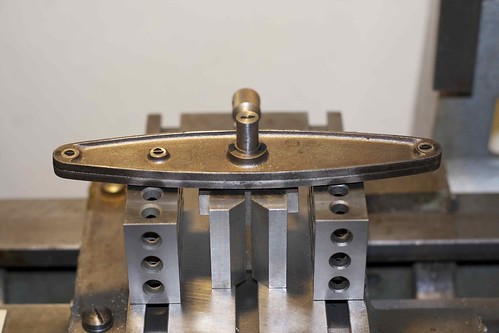
So I pushed out the bronze bushings that I'd made earlier, and turned new, solid bushings, which I plan to drill in situ. Since I was doing one, I decided to do the other two spindle bushings too, and re-locate the holes as well as straightening them. With the bushes fixed in place with Loctite, I then tried to figure out how to mark things up:
The important thing is that the spindle holes are aligned with the center of the main spindle, so here the beam rests on V-blocks while I try to find a centerline through the center of the main spindle, to mark on the bushings. I'll use this to align the part on the mill.
Likewise, I want to ensure that the spindle holes are drilled parallel to the main spindle, so I think I'll use a setup something like this:
where the main spindle is held in a V-block on its side. That's not my final setup; way too much overhang on the ends ;D
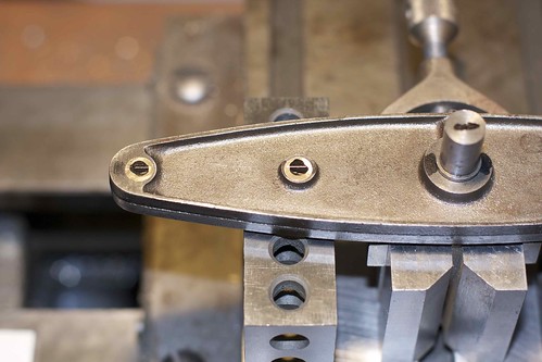
It's interesting how far off the centerline is from the original holes:
so the original builder didn't seem to be very accurate with the beam. I just hope none of my holes hit the edge of the bushing!
So tomorrow I'll have a go and fixing this down (without twisting!) and drilling. Hey, at least I can push out the bushings and make new ones if I mess up!
- Joined
- Oct 29, 2011
- Messages
- 287
- Reaction score
- 2
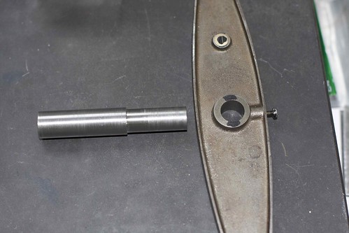
Got a little bit more done today. I turned a mandrel to hold the beam during machining, since I wanted a longer length to hold in the V-block, and the original spindle is a sloppy fit (which is OK while running, because it's held in with a lock screw).
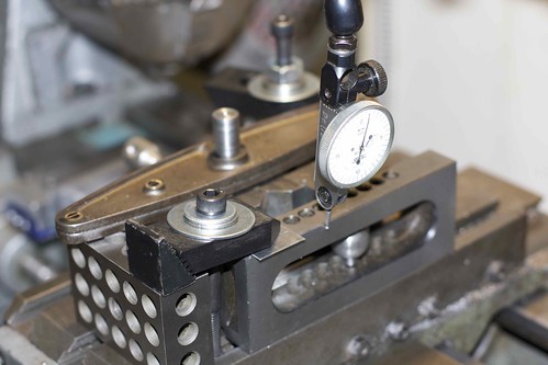
With that secure in a V-block, which was held in turn in a 2" vise, I aligned the beam so that the centerline was parallel to the plate (and thus the base of the vise):
and marked out a line on the bronze bushings. I had to take care to not knock this out of alignment for the rest of the operation. Now onto the milling table on my Emco Maximat. I had to go front-to-back because the table is deeper than wide, which required moving the part for each end. Here I'm indicating on the base of the vise to ensure that's it's parallel with the direction of travel:
and found that just aligning the vise to the edge of the table was good. Then I centered on the mandrel:
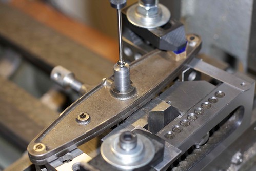
I'm using a ball-end wiggler; with the mill running, I move the quill wiggler lightly into the center drill hole, and can see when the wiggler gets pushed aside when misaligned. I took care to pack under the beam with shims to avoid torsion when clamping.
Now I can use the dials (double-checked with calipers) to move over the required 3.5" to drill and ream:
Then I flipped the whole fixture around and repeated the operation for the other two holes. A quick fitting suggests that this solved most of the binding at the crank end, but I had to dash off to a social obligation, so the real test will have to wait! ;D
With that secure in a V-block, which was held in turn in a 2" vise, I aligned the beam so that the centerline was parallel to the plate (and thus the base of the vise):
and marked out a line on the bronze bushings. I had to take care to not knock this out of alignment for the rest of the operation. Now onto the milling table on my Emco Maximat. I had to go front-to-back because the table is deeper than wide, which required moving the part for each end. Here I'm indicating on the base of the vise to ensure that's it's parallel with the direction of travel:
and found that just aligning the vise to the edge of the table was good. Then I centered on the mandrel:
I'm using a ball-end wiggler; with the mill running, I move the quill wiggler lightly into the center drill hole, and can see when the wiggler gets pushed aside when misaligned. I took care to pack under the beam with shims to avoid torsion when clamping.
Now I can use the dials (double-checked with calipers) to move over the required 3.5" to drill and ream:
Then I flipped the whole fixture around and repeated the operation for the other two holes. A quick fitting suggests that this solved most of the binding at the crank end, but I had to dash off to a social obligation, so the real test will have to wait! ;D
- Joined
- Oct 29, 2011
- Messages
- 287
- Reaction score
- 2
With the new beam in place, I could now adjust the piston rod. Luckily it had to be shortened, rather than lengthened ;D I just machined the shoulder at the piston end back by 0.056", lengthened the threads a little, and trimmed off the end. After some more tweaking of the connecting rod, things turn over quite nicely now.
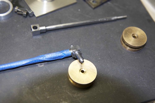
The next thing I need to do is to fix the piston to its new base, which means transferring the holes from the piston to the base, which is the opposite of the usual order. I think I'm going to use paper to do that somehow.
The next thing I need to do is to fix the piston to its new base, which means transferring the holes from the piston to the base, which is the opposite of the usual order. I think I'm going to use paper to do that somehow.