Spark source

Home Model Engine Machinist Forum

Help Support Home Model Engine Machinist Forum:

This site may earn a commission from merchant affiliate links, including eBay, Amazon, and others.

flyingtractors1

Well-Known Member
Joined
Dec 3, 2011
Messages
236
Reaction score
99
Hi All. I'm determined to build an IC engine - a first for me, and am gathering up likely parts, components, etc. Would a Model T coil & 6 volt lantern battery be a good spark source to use for this venture? Would a condenser be needed somewhere in the circuit? Thanks. Ralph
 
Ralph,

Yes and Yes and Yes.

Wiring.jpg


Best Regards
Bob
 
Thanks Bob, but I don't understand the diagram. Is everything grounded at the "motor"? scratch.gif
 
Would a Model T coil & 6 volt lantern battery be a good spark source to use for this venture? Would a condenser be needed somewhere in the circuit? Thanks. Ralph

A model T coil usually refers to the type of 'buzz' coil that has a vibrating reed and generates many sparks.

The circuit shown looks more like the conventional spark coil with points and a capacitor.

Which kind of coil are you asking about? A model T type does not need an external capacitor, it has one built in.
 
Bob, yea; I get it. What function does the condenser serve? Thanks again. Ralph
 
The simple explanation for the condenser is to prevent the erosion of the points and the breaking down of insulation on the coil windings.
 
I found a buzz coil that delivers a pretty good jolt, and it makes a good spark too - when it's not grounded through me. :-\ Thanks for the help. I'll play with it some more now that I've learned how to wire it - shuda asked sooner and spared myself the shock therapy.
 
How do you time a buzz coil?
BTW, don't leave the condenser out. It won't work with out it. Need a resistor in the power wire too. You can buy coils with a built in resistor or add 10 ohms in series outboard. Get a high wattage one from Radio Shack.
 
How do you time a buzz coil?
BTW, don't leave the condenser out. It won't work with out it. Need a resistor in the power wire too. You can buy coils with a built in resistor or add 10 ohms in series outboard.

I think you really don't understand a buzz coil. They simply need a contact point to close to supply DC. They do not need external ballast resistors or capacitors. They do have a capacitor inside the box.

In a buzz coil the vibrating reed on the end of the coil causes the primary coil to be interrupted many times per second. The spark plug sees multiple sparks, good for ignitions that may not be precisely timed, like model Ts.

The buzz coil went out of use when Kettering invented the modern coil. This coil makes just one big spark when the points open, because of the collapsing magnetic field. The coil is 'charged' during the time the points are closed. Thats caused dwell- remember dwell meters to set points?

A resistor is needed because the coil primary is very low resistance, and the current through it would be limited only by this resistance, particularly when the engine happens to stop with the points closed. While the engine is running the current through the coil is limited by the inductive effect- it takes time for the current to reach the max value, and when running the points open before they reach saturation of the coil.

The capacitor does help protect the points, but it is really there to store the charge from the collapsing magnetic field. Without it the field would see a relatively high resistance across the opening points and reduce the rate of drop of the voltage. A capacitor looks llike a very low resistance to the changing current.

See http://en.wikipedia.org/wiki/Kettering_ignition_system for a more detailed explanation.
 
You're right, I don't understand the workings of a buzz coil. I was soliciting an explanation.

So does the points start the coil buzzing and does it buzz until the points open? Seems like it'd use up a lot of battery and get pretty hot working like that. Does the buzz coil buzz all the time with the distributor cap providing the timing? How's it work?

My comment about the necessary ballast resistor and condenser was in regard to the Kettering ignition suggested in a previous post.

Sorry if I sounded curt.
 
So . . . just connect the battery (negative to ground) in series with the breaker points? Then one of the spark poles of the coil to ground and the other to the spark plug -- and that's it?
 
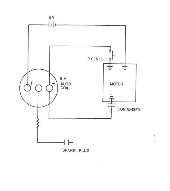
Again we have a diagram of a Kettering type ignition, not a buzz coil.

The Ford model T coil was housed in a wood box, about 2x3x5. Inside is a coil of wire on an iron core. There are two coils a primary and a secondary, as in the Kettering coil. But in a buzz coil at the end of the iron core is a set of points arranged so that when the coil is magnetized the points are pulled open. When power is applied the magnet pulls in whats called an armature, which is fixed on a leaf spring and has the contact points at its end.

When current is applied the coil becomes a magnet and breaks the circuit. Current stops flowing, the field collapses, and a high voltage is induced in the secondary. But when the magnetic field drops the spring loaded armature again closes the points, current flows again and the cycle is repeated. This is exactly like a doorbell or buzzer. As long as power is applied to the coil it continues to buzz, at a maybe 1khz rate.

The distributor only switched the low voltage- there was a coil for each plug. When the points closed many sparks were generated in the plug, hopefully at least one of them ignited the mixture.

Besides ignition for model Ts they had a lot of other great uses. The high voltage sparks could be connected to many things, like car seats, urinals, door knobs, anything likely to be touched by an unsuspecting person. Not that I every played such pranks, Ive only been told about them ;D

They were/are often used on single cylinder farm type engines.
 
It is my understanding that the Kettering type ignition's coil started out as a 6 volt coil. When the automobile manufacturers went to the 12 volt system for the advantage of the 12 volt starter motor over the 6 volt motors, they used the same 6 volt coil and fed it through a ballast resistor. This resistor was mounted external to the coil and was quite noticeable. Some manufacturers decided to 'pretty up' the installation by enclosing the resistor within the coils can. These are marked as 12 volt coils. Others did away with the large ballast resistor by using a special resistance wire to connect the battery to the 6 volt coil. This only caused problems when an unknowing shade tree mechanic would replace this special wire with an ordinary copper conductor thus feeding the 6 volt coil with the full 12 volts from the battery.

Just a little trivia.

Rolla
 
Have you ever thought of using a magneto?

Totally self contained, no batteries, coils etc. Just mechanically fit to the engine and away you go.

This is the magneto I built lashed up to run a friend's Webster.

[ame]http://www.youtube.com/watch?v=-jROBQpAMZg&feature=related[/ame]


John
 
Thanks Jim. That drawing is a work of art and easy to understand. I'm a visual learner, and your sketch talks to me in terms that are easy to grasp. Ralph
 
Thanks John. I like that Webster with the magneto ignition, but I can't get quite enough information from the video. Do you have - could you sketch out a more descriptive / detailed drawing or pictures? Ralph
 
Hi Ron. Good explaniation. I think that I understand it. That's why it's called a "Buzz" coil - the "points" are part of the unit, and I see that there is a wrapped cpacitor in the box ( just had to take one apart). And now I have other ideas for the use of a buzz coil - not that I would do any thing sneaky, but I've now heard of such things and can imagine others. :idea:
 
Back
Top