


mklotz
Well-Known Member
I'm in the process of building Bill Harris' steam roller. Jeff02 is also building it - you can follow his progress here...
http://www.homemodelenginemachinist.com/index.php?topic=8716.msg93353;topicseen#new
Given the length of the project, my laziness and not wishing to compete with Jeff, I'm not going to do a build thread.
However, I promised Zee that if anything worth reporting happened, I would be sure to pass it along. That's the object of this thread. Some of this will be boring to our more experienced members but I sympathize with many of our members who claim the visual prodding induced by seeing how someone else does something, even the ordinary stuff, can be very helpful. I'll try to stick to things that at least have some chance of satisfying that objective.
On with it...
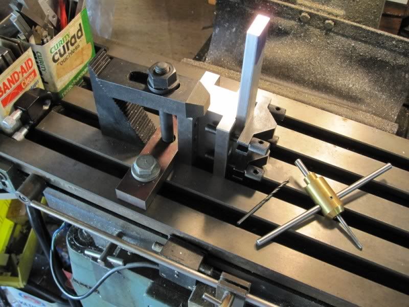
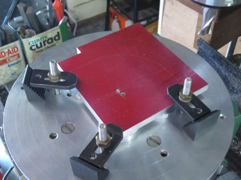
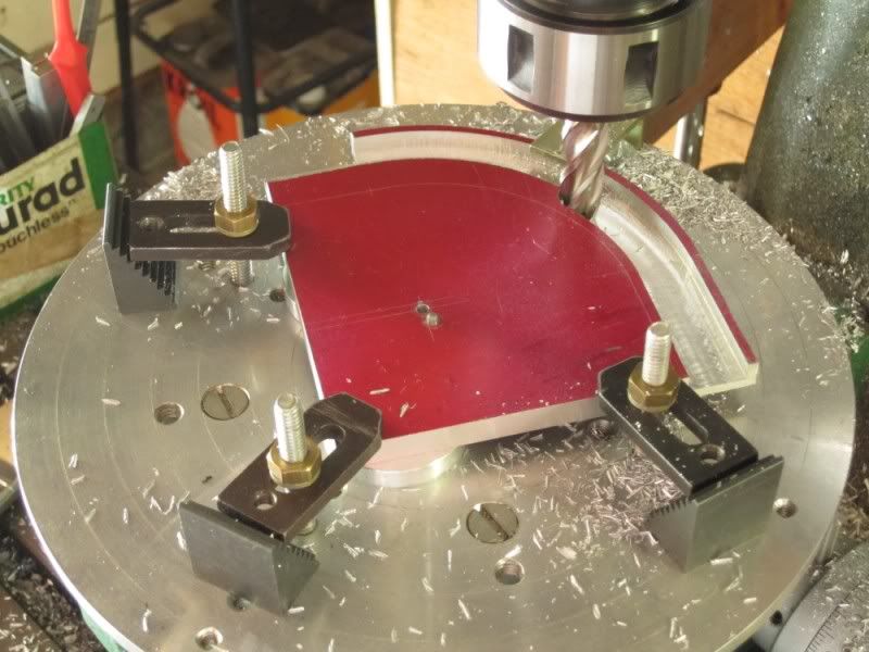
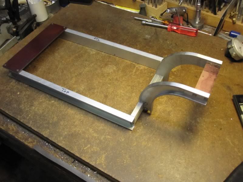
Today's job was to square and bring to size a 1/8" plate that is the base for the engine and boiler. I seldom mill directly on the table but the size (5-5/8 x 7-3/8) of the part demanded that so I set it up as shown below.
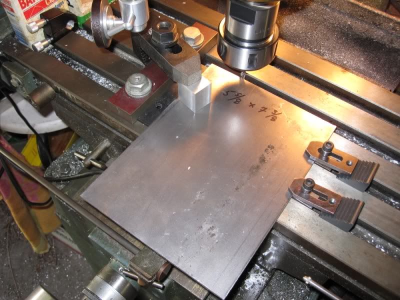
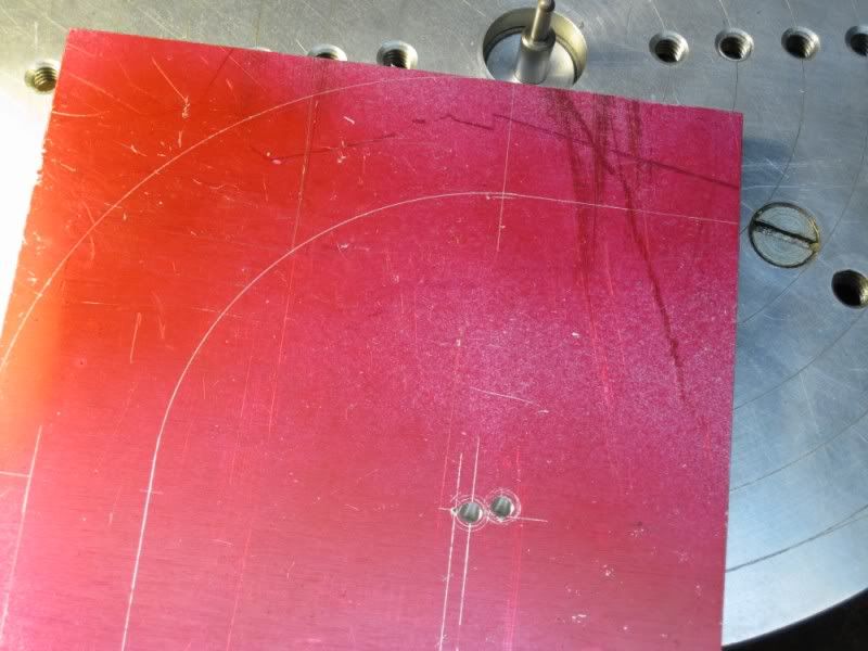
Years ago I made an alignment block for jobs like this. You can see its red top near the top of the picture. It has three holes spaced the same as the table T-slots so it can be bolted down in a variety of postures. Its reference surface has a small undercut so errant swarf can't interfere with alignments. Using a DTI, I aligned it with the Y-axis to serve as my master reference.
Note that clamp studs are not used to secure it. If you do this, use low profile bolts as I did lest the studs interfere with the spindle. It's a lesson I learned from experience.
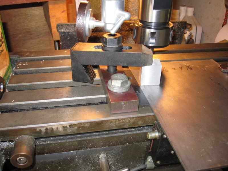
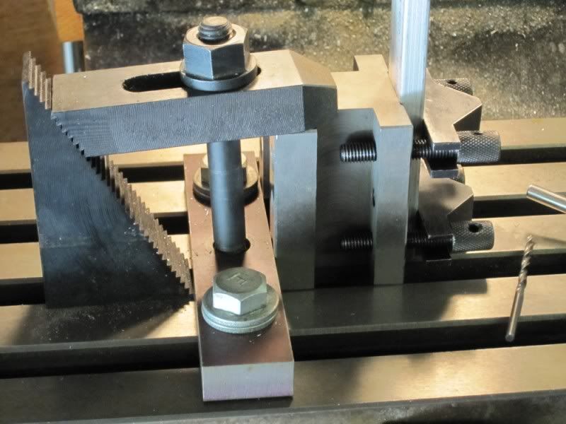
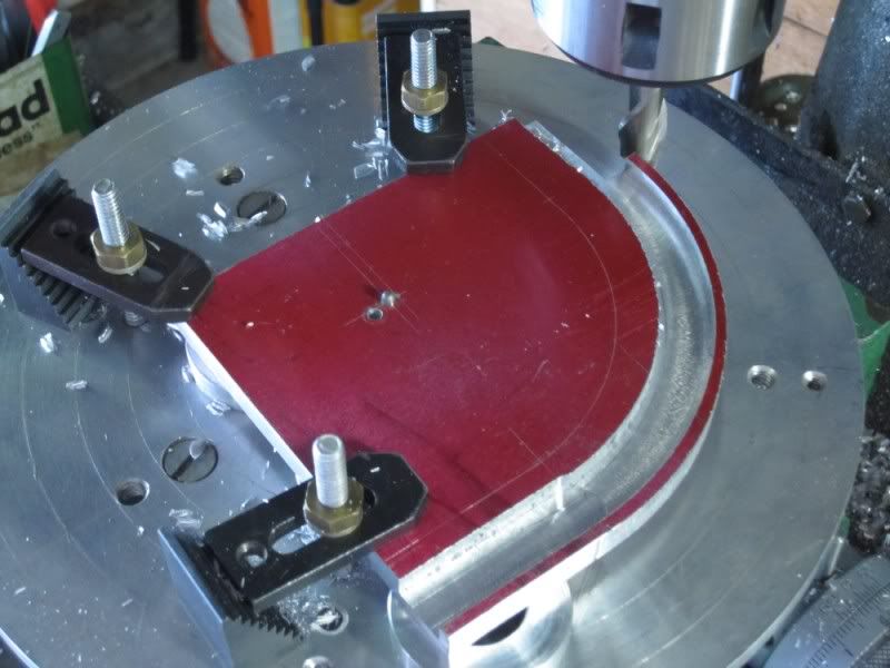
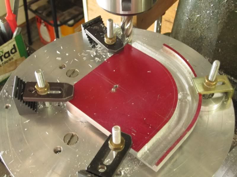
The three holes are important too. Two bolts are plenty to secure the reference bar but, as you can see from the photo, the third hole allows one to mount a clamp right in the middle of the reference bar - exactly where you are most likely to need a clamp - trust me. The next photo shows the clamping arrangement in more detail...
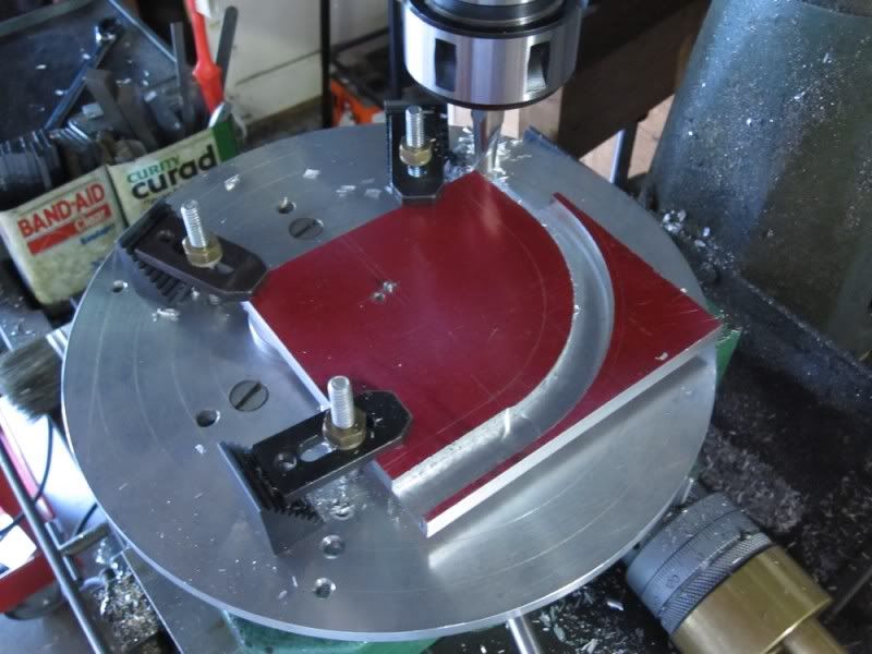
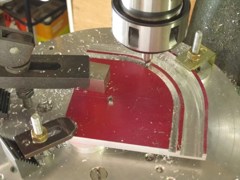
Referring to the first photo again, the workpiece is butted against a parallel butted against the reference bar. This pushes the edge to be milled away from the reference so I can cut all the way to the edge. The edge to be cut is aligned with one of the T-slots so that the milling cutter will have clearance below the workpiece.
The other end of the workpiece is secured with two of my smaller clamps. Whenever possible, I prefer to use my smaller clamps to maximize the vertical clearance for the spindle. I've standadized on 1/4-20 for all my small clamps so I made up a collection of 1/4-20 T-nuts that fit the mill T-slots. One of the smaller clamps would probably be adequate but I'm a belt-and-braces type of guy.
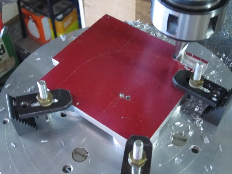
Now, I just know someone is going to ask what that silvery thing hanging into the photo frame from above. It's a midget tripod head that I picked up in a camera store.
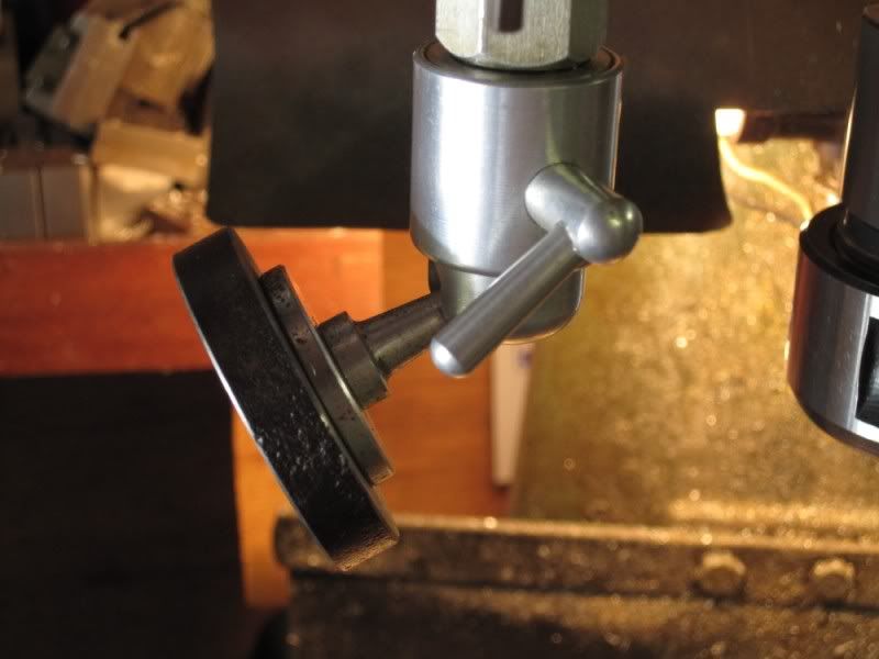
I replaced the nut that secured the bottom of the mill depth gauge with a union nut and screwed the tripod head into that. This means it maintains a fixed relation to the spindle (and tool) as the spindle is moved up and down.
It's aluminum so I fitted it with a steel plate so that I can attach various magnetic stuff to it - like this multi-LED light...
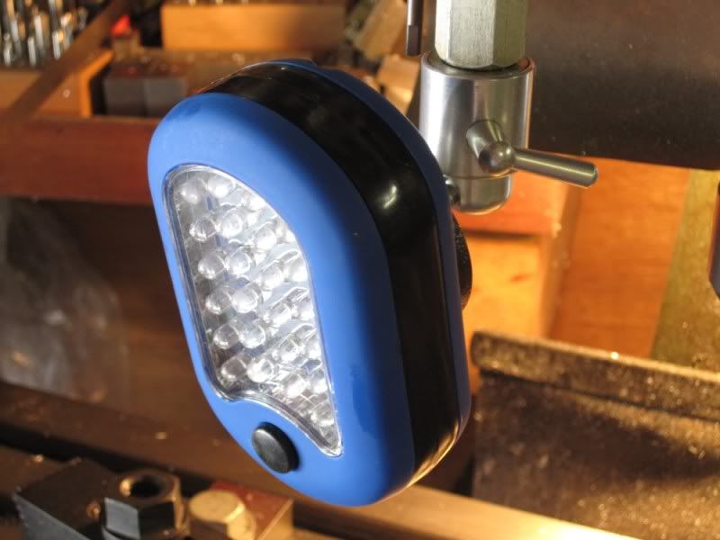
picked up for a couple of bucks at, where else, Harbor Freight.
Regardless of where the spindle is, the light is always shining on the tool in use and, when I need light elsewhere it's easy to pull it off and use it as a hand-held "flashlight".
I'll add to this thread as I do more things that I think might be quasi-inspirational but, in the meantime, feel free to add any ideas you have that might give others useful ideas.
http://www.homemodelenginemachinist.com/index.php?topic=8716.msg93353;topicseen#new
Given the length of the project, my laziness and not wishing to compete with Jeff, I'm not going to do a build thread.
However, I promised Zee that if anything worth reporting happened, I would be sure to pass it along. That's the object of this thread. Some of this will be boring to our more experienced members but I sympathize with many of our members who claim the visual prodding induced by seeing how someone else does something, even the ordinary stuff, can be very helpful. I'll try to stick to things that at least have some chance of satisfying that objective.
On with it...
Today's job was to square and bring to size a 1/8" plate that is the base for the engine and boiler. I seldom mill directly on the table but the size (5-5/8 x 7-3/8) of the part demanded that so I set it up as shown below.
Years ago I made an alignment block for jobs like this. You can see its red top near the top of the picture. It has three holes spaced the same as the table T-slots so it can be bolted down in a variety of postures. Its reference surface has a small undercut so errant swarf can't interfere with alignments. Using a DTI, I aligned it with the Y-axis to serve as my master reference.
Note that clamp studs are not used to secure it. If you do this, use low profile bolts as I did lest the studs interfere with the spindle. It's a lesson I learned from experience.
The three holes are important too. Two bolts are plenty to secure the reference bar but, as you can see from the photo, the third hole allows one to mount a clamp right in the middle of the reference bar - exactly where you are most likely to need a clamp - trust me. The next photo shows the clamping arrangement in more detail...
Referring to the first photo again, the workpiece is butted against a parallel butted against the reference bar. This pushes the edge to be milled away from the reference so I can cut all the way to the edge. The edge to be cut is aligned with one of the T-slots so that the milling cutter will have clearance below the workpiece.
The other end of the workpiece is secured with two of my smaller clamps. Whenever possible, I prefer to use my smaller clamps to maximize the vertical clearance for the spindle. I've standadized on 1/4-20 for all my small clamps so I made up a collection of 1/4-20 T-nuts that fit the mill T-slots. One of the smaller clamps would probably be adequate but I'm a belt-and-braces type of guy.
Now, I just know someone is going to ask what that silvery thing hanging into the photo frame from above. It's a midget tripod head that I picked up in a camera store.
I replaced the nut that secured the bottom of the mill depth gauge with a union nut and screwed the tripod head into that. This means it maintains a fixed relation to the spindle (and tool) as the spindle is moved up and down.
It's aluminum so I fitted it with a steel plate so that I can attach various magnetic stuff to it - like this multi-LED light...
picked up for a couple of bucks at, where else, Harbor Freight.
Regardless of where the spindle is, the light is always shining on the tool in use and, when I need light elsewhere it's easy to pull it off and use it as a hand-held "flashlight".
I'll add to this thread as I do more things that I think might be quasi-inspirational but, in the meantime, feel free to add any ideas you have that might give others useful ideas.
")