Rupnow Ovehead Cam Air Cooled

Home Model Engine Machinist Forum

Help Support Home Model Engine Machinist Forum:

This site may earn a commission from merchant affiliate links, including eBay, Amazon, and others.

Brian Rupnow

Design Engineer
Project of the Month Winner
Joined
May 23, 2008
Messages
14,991
Reaction score
8,285
Location
Barrie, Ontario, Canada
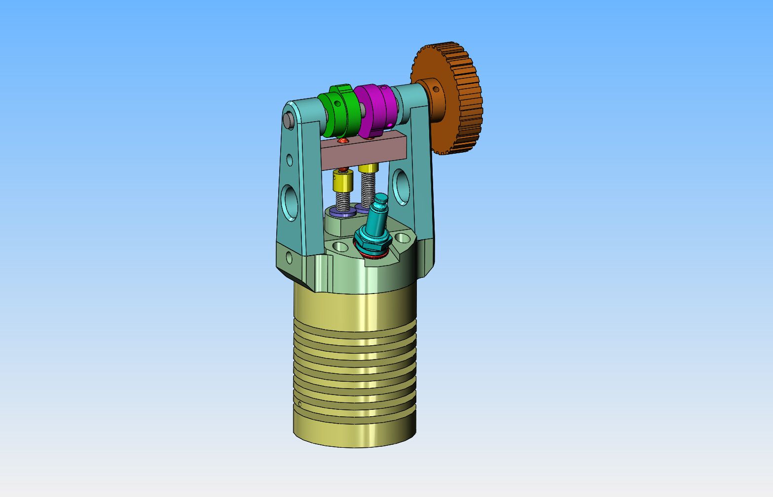
This morning I'm setting around with some free time, and I've been thinking for a while now about an overhead cam air cooled engine. There are a lot of horizontal and vertical cylinder engines out there, but I haven't seen very many single cylinder engines like the old "Iron Horse" washing machine engines with the cylinder on a 45 degree angle. My thoughts of course, were that if you could hang the entire camshaft off the cylinder head, then it would give you the freedom to run the cylinder on just about any angle you wanted. By using a cogged belt drive to the camshaft instead of a gear train, that opens up even more freedom with placement of components. I looked through all of the engines I have built over the past few years, and ended up leaning heavily on my Atkinson for some of this, so if it looks a bit familiar, then that is why. I'm not saying I'll actually build this, but you know how it is------Brian
 
Well----At this point in time it looks Ahhh---Interesting!! I've been waiting most of the day for a call back from a customer, and while I wait I can "doodle". As shown, it has a 1" bore, a 1 1/8" stroke, and that is a 5 1/8" flywheel setting on there. The crankshaft is 3/8" and runs on two sealed ball bearings at each end. The crankshaft is a two piece unit. The "driver" end which supports the flywheel and has the rod journal on it is one pressed together assembly, the other part of the crank is a "follower crank" and will ultimately drive a cogged pulley and the ignition points. The cogged pulley shown on the cam shaft is only about half the diameter it will end up being in reality.--There may even be a way to incorporate fan blades into the camshaft pulley to blow a stream of cooling air over the cylinder.
 
The only bearings that will need lubrication in the engine itself are the con rod big end and the wrist pin. The con rod big end is very easily accessible for a squirt of lubricating oil from my trusty oil can. The wrist pin, however, is hard to get at to oil. Since this is a 1" diameter piston, I am going to try and find room in the small end of the connecting rod for a sealed ball bearing. I won't do that at the big end because it throws the crankshaft too out of balance.
 
I was able to shorten up the blue towers considerably, by getting rid of the pellet shaped pushrods completely and letting the cams push right on the end of the hardened yellow caps. These yellow caps are closed on the end that contacts the cap, and open on the other end to contain the valve spring and for a pinned connection to the end of the valves. The transparent bar guides them and keeps the cam from putting any side load on the valve stem. I thought about how to tie the two sideplates together and decided that a piece of 3/8" thick aluminum angle would be just the ticket. It provides rigidity to the sideplates, and also acts as a great containment for any oil slung off the big end of the con rod. I will mill a recess for a polished brass cover plate which has super magnets embedded into the underside of it, and put some ferrous plugs in the aluminum side plates for the magnets to stick to. this allows me to remove the cover plate, give the big end of the rod a squirt of lubricating oil, then put the cover plate back into place. I am not a fan of oil filled crank cases.


Looks like a great project for this coming winter. Just waiting on a new set of contact points to arrive for the Rupnow Vertical and if all goes well I'll be ready for another project.
 
So---The plot thickens---a little bit. I see that with an adapter, I can mount one of my Traxxas carburetors. I could build my own carburetor, but why make more work? I hunted around on my old Atkinson engine thread from back in 2012 and found the name of the company I bought the timing belt and pulleys from. This time I need two pulleys, one exactly twice as big as the other for my 2:1 ratio, and since I now know what my center to center of pulleys are, I was able to call the company in North Carolina that supplied the pulleys 5 years ago and ask for price, delivery, and 3D solid models of the pulleys. I added an exhaust "muffler" and manifold to the engine. (I may rethink the shape of that exhaust manifold, I'm not sure yet). It doesn't show in the model, but I have rejigged those magenta coloured bearing housings to set in tighter to the engine sideplates. The timing belt pulleys on the engine are not updated yet.--I have to get the new 3d models before I can do that.
 
I was wondering about where to put the ignition points. Once again the beauty of a single cylinder engine being able to run a "waste spark" system has saved me. I can fit them on the side opposite to the flywheel and run them off the crankshaft. Although the top timing belt pulley up at the cam is going to be twice as large as the diameter shown, the small pulley down at the crankshaft is going to stay very close to what is currently shown.
 
Admiral_dk--as per your suggestion, I have swapped the position of the exhaust pipe and the carburetor. I don't know yet if I will leave that strange little intake manifold in place, or remove it completely and let the carb stick out at 90 degrees from the cylinder. That might look good with a really well shaped air intake horn.
 
I like the idea of the guide block for the cam followers. Otherwise the tall valve stems might end up putting a lot of sideways strain on the valve guides due to cam wiping action. Or could you not make the valve springs and stems shorter and the follower the shape of an upturned bucket that sits down over the springs to make it more compact? Probably would still need the guide block though.? Seems that is the way they do it on the DOHC Honda motorcycle engines I work on sometimes and I have always been very impressed with the way Honda do things.
 
I had to move the cylinder intake port around again, as there was no way to get a gas tank mounted with the previous configuration. This will work out pretty good, I think. The exhaust pipe discharges out between the timing belt drive, and the carburetor sucks in fresh air from the flywheel side. I had to make my "crank-case access hatch" a bit smaller as the gas tank covered the top portion of it, but I still have lots of room to get in there with a squirt can. I am going to have to rethink the use of a ball bearing in the small end of the con rod. A 3/16" i.d. ball bearing is 1/2" o.d. and there simply isn't enough room for it.--And nobody sells a 3/16" sealed roller bearing.
 

Brian
go to hobby shop they use that size on RC boat

needle bearingbrian.jpg
 
A big THANK YOU shout out to Luc from Quebec for putting me onto R.C. ball bearings at the hobby shop. I bought two 3/16" i.d. sealed bearings that measure 0.311" outside diameter x exactly 0.125" thick. These two will set side by side in the small end of my 1/4" thick connecting rod. They are part #DTXC1413, and cost $2.49 each. Yes, I do realize that ball bearings are not recommended for something like a wrist pin, which only oscillates back and forth, but doesn't spin fully around. However, they have to be better than a bushing with no lubrication at all. Time will tell about that one. I also bought four 1/4" sealed flanged ball bearings that are 0.421" diameter over the flange, 0.375" over the other diameter, and have a total thickness of 0.125". Each camshaft support tower will receive two of those. They are part #DTXC1517 and cost $3.99 each. This means that the only bearing surface on this entire engine that doesn't have a ball bearing will be the big end of the con-rod, which will probably get an oilite sintered bronze bushing, and will be easily accessible for oiling by removing the magnetic "inspection hatch" cover.
 
I keep moving things around, looking for the "ideal" configuration. I got my information today on that 60 tooth pulley that goes on the cam shaft, and it's big enough in diameter that my exhaust pipe was going to run thru the side of it. I messed around a bit having the exhaust come out of the cylinder and point straight up, but that not only looked a bit dumb, but would have covered the entire engine in oil spatter after five minutes of running. Then I had a new thought and turned the cylinder head around 180 degrees on the cylinder. I like that!! I can still have the carburetor where it was before, and have the exhaust pipe pointing down and away from everything.
 
That is a massive pulley on the top end - do you really need 30:60 teeth or maybe something smaller like 15:30 or 20:40?
 
There are things going on down at the bottom pulley that preclude making it smaller. That top pulley may very well get modified to have a fan incorporated into it.
 
Why yes, I DO have a rotary table!!!--And sometimes I do use it for making something other than gears. I have turned the crank on this one so many times this morning that I'm thinking of changing my name to "Crankenstein". If I don't manage to screw this up before I get finished, it is going to make a very pretty little cylinder head.
 
When I first looked at the cylinder head detail, I immediately had a big whine and thought "Oh, but this is going to be so hard.---Wahhhhh". Then I thought "Yes, but I've designed similar "hard to make" parts over the last fifty years, and never gave a second thought for the poor guy in the machine shop who actually had to build the parts. So, since I liked the design, I went ahead and made it to the drawing. Lots of work and multiple set-ups there, but I like the finished part. And every part like this that I make stretches my abilities just that little bit more.---I did change the timing belt pulleys.--went from 30 tooth and 60 tooth down to 20 tooth and 40 tooth. Proportions look a lot better now.

 
It's a whole new world running a lathe with a DRO on it. First observation is that no matter how well placed the display unit is, you can't watch both it and the tool tip at the same time. You can watch one, or you can watch the other, but there is no way in Hell to watch both at the same time. When the lathe is in "power feed" mode, those numbers change awfully quick. The first pass isn't too bad, because there is no shoulder on the part being turned. By the time you get to the third pass, there is a pretty good shoulder formed on the part, so you definitely don't want to over-travel. Working with a DRO is a lot like that old-time religion.--You just got to have faith!!! That is a piece of grey cast iron in the chuck, and I'm taking 0.020" depth of cut at about 260 rpm. with a brazed carbide tool. The o.d. on that cast iron is crusty, rusty, and kind of horrible. I chuck it up in my lathe semi-tight, then use my "bump tool" to bring it to as close as I can get it to running true, then tighten the chuck up all the way. the material is larger than the bore in my spindle, so I put a center countersink in the non chuck end and then run a dead center in my tailstock chuck to assure that it doesn't come bounding out of the chuck and chase me around the room. I had that happen once, and it is a life altering event!! I leave the lathe in "power feed" until I see the last 0.100 of travel come up on the display, then kick out the power feed and finish the travel with the big wheel on the front of the apron.
 

Latest posts

Back
Top