RUBY KOUHOUPT MARINE ENGINE

Home Model Engine Machinist Forum

Help Support Home Model Engine Machinist Forum:

This site may earn a commission from merchant affiliate links, including eBay, Amazon, and others.

Don1966

Senior Member
Joined
Jan 19, 2012
Messages
487
Reaction score
24
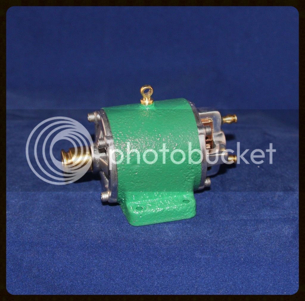
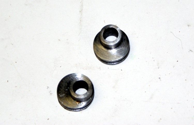
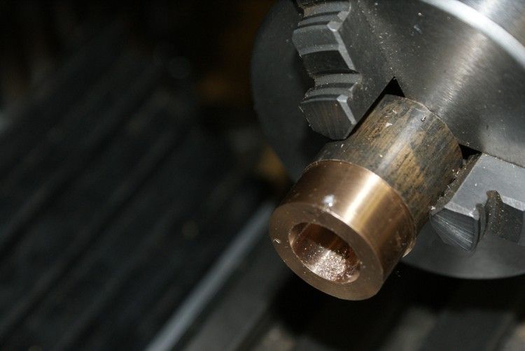
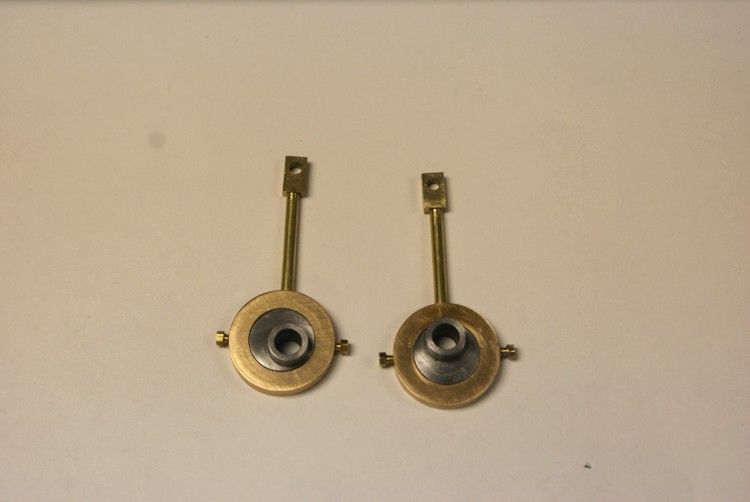
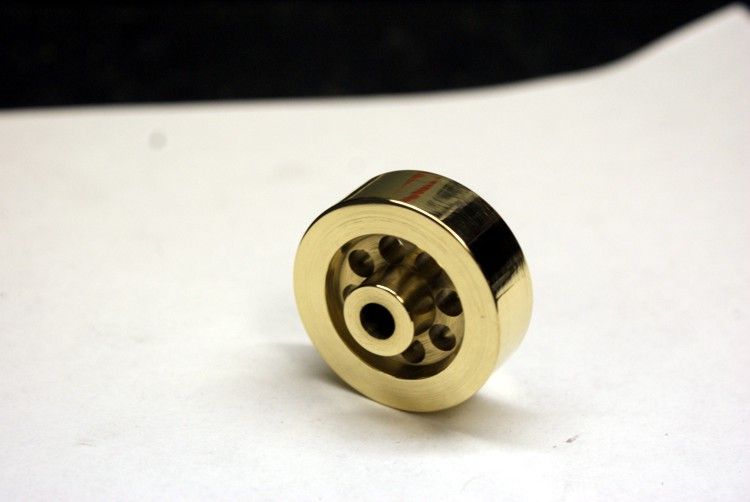
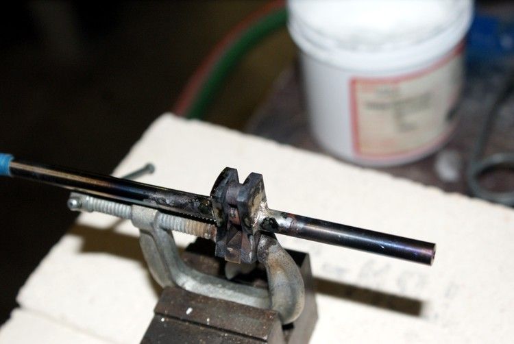
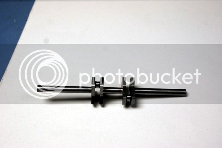
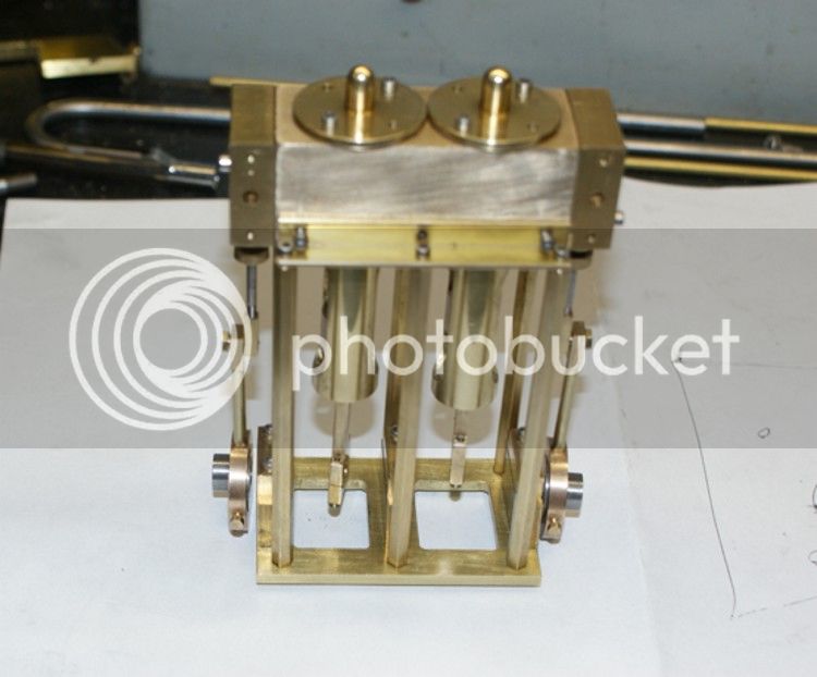
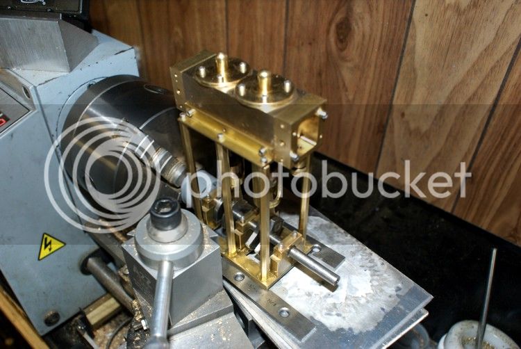
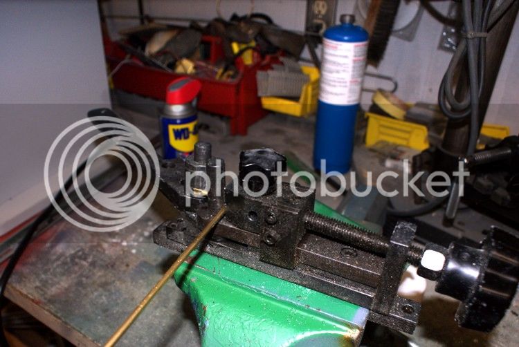
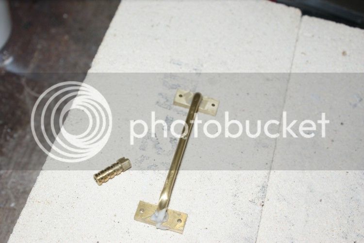
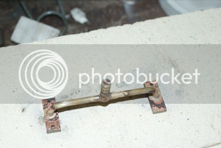
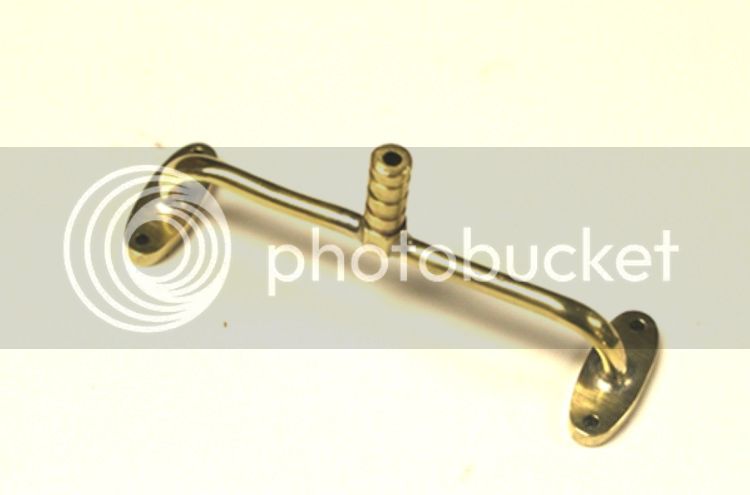
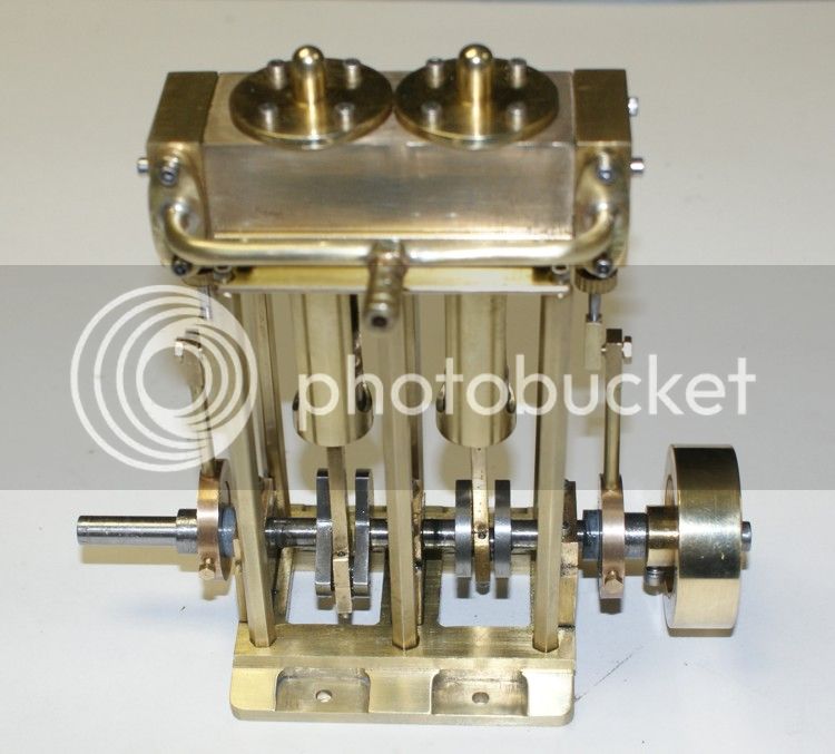
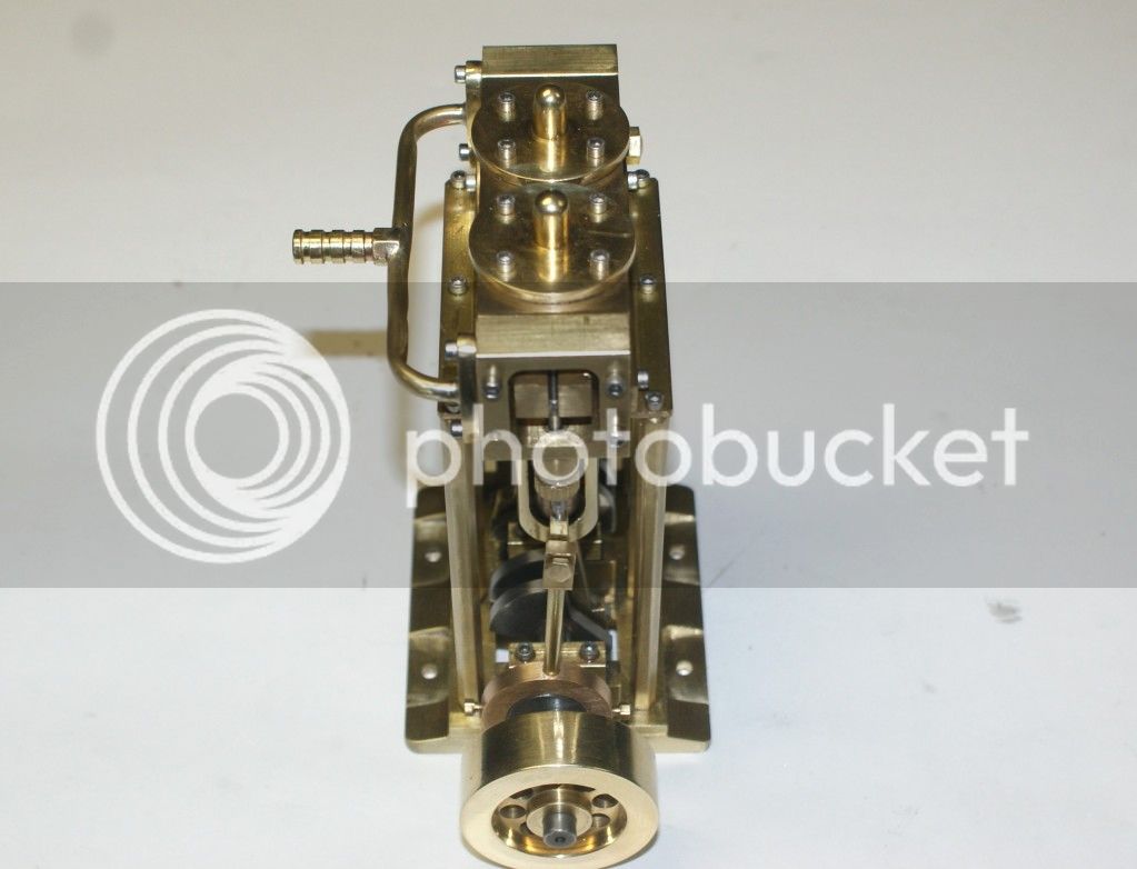
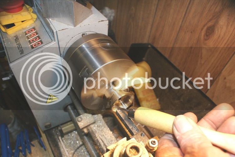
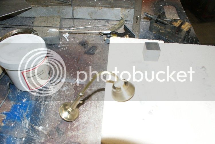
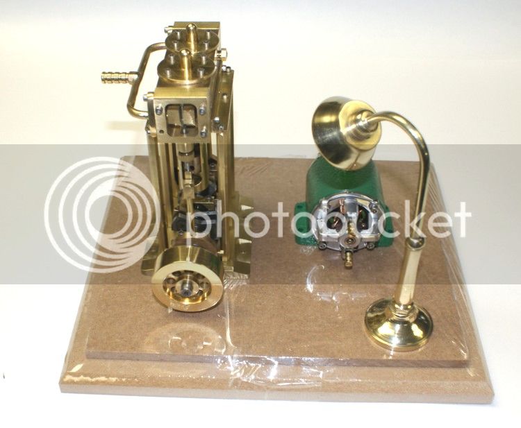
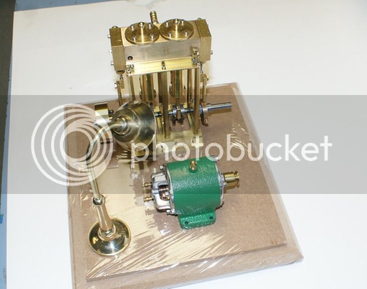
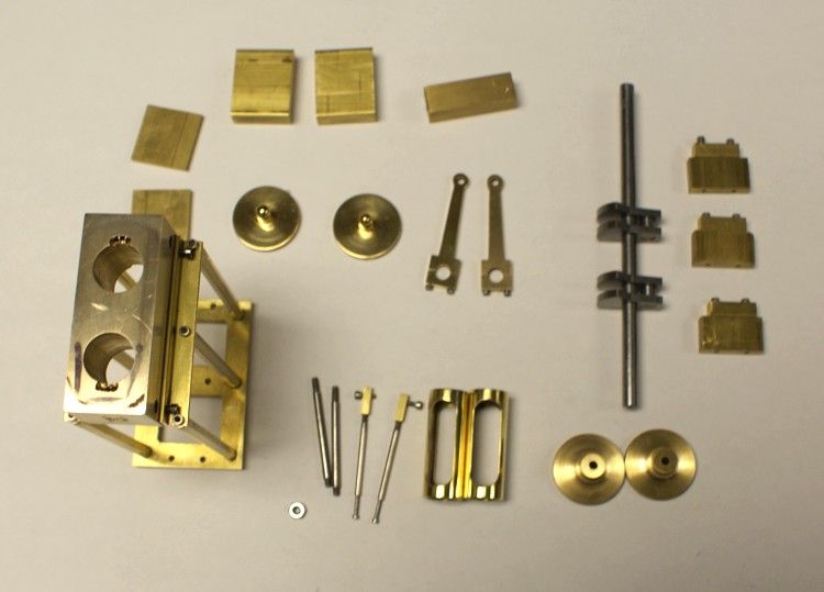
I had started this engine before I started taking photos and documenting. I have attached the photo of the parts that were already made and will start for there to the final assembly. The cylinder is made from bronze, the shaft and throw lobs were made from tool steel, steam chest is brass, piston and steam chest linkage stainless and the frame and steam chest all brass.

NO28.jpg

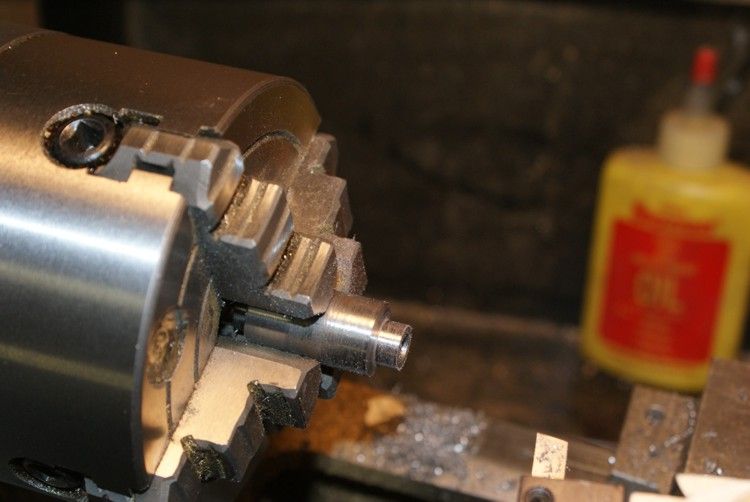
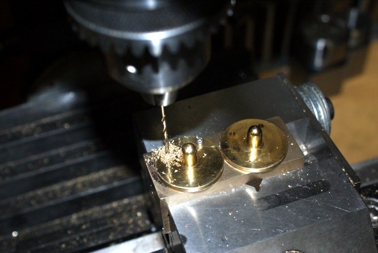
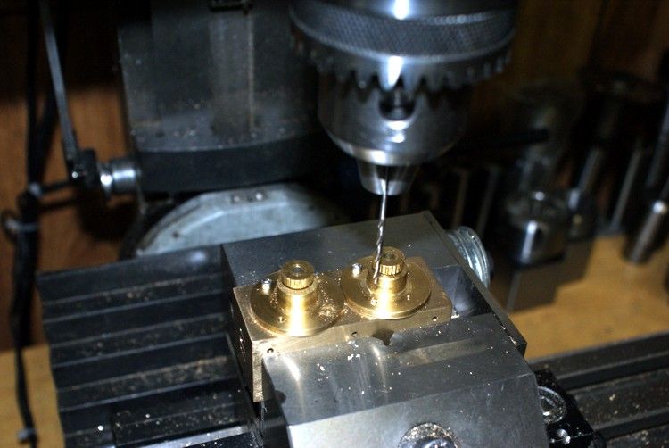
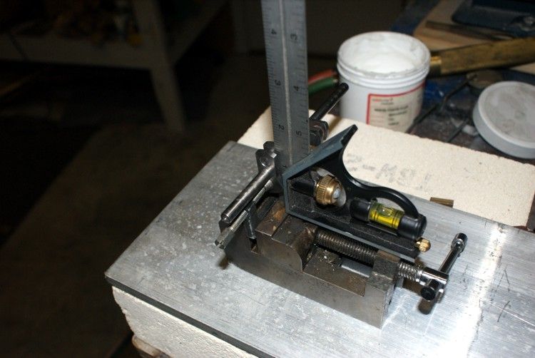
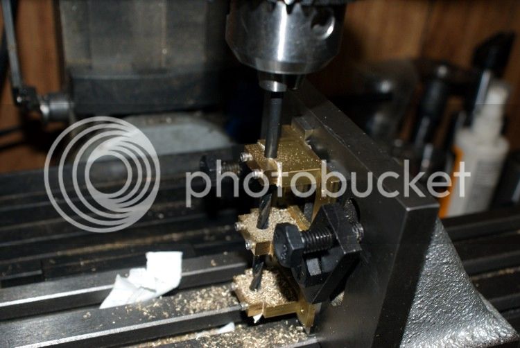
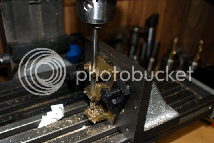
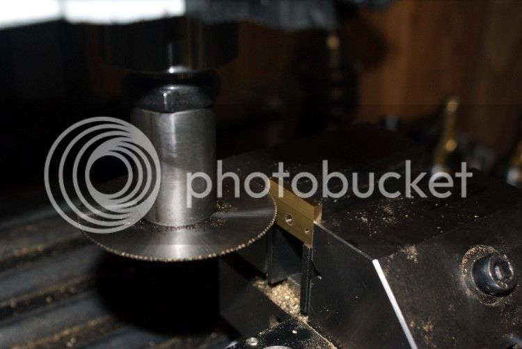
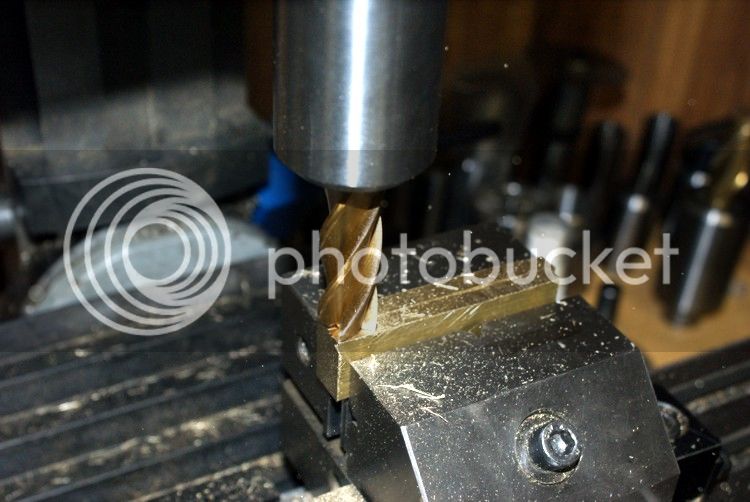
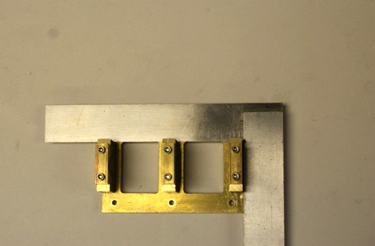
Squaring off the pillar block bearings
NO5.jpg

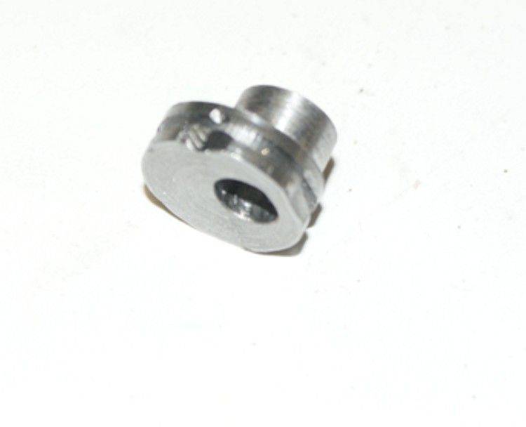
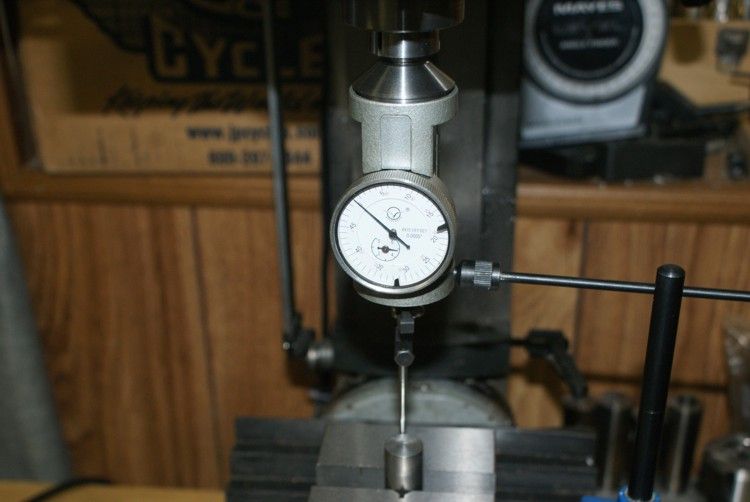
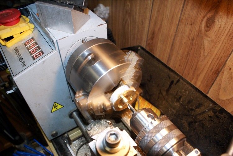
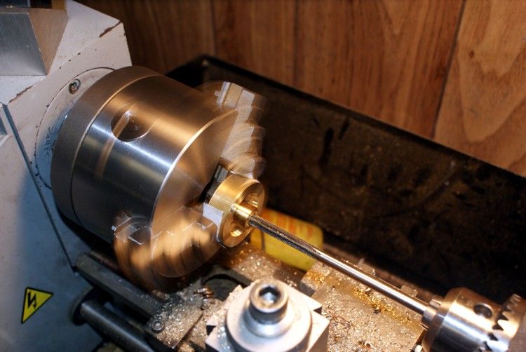
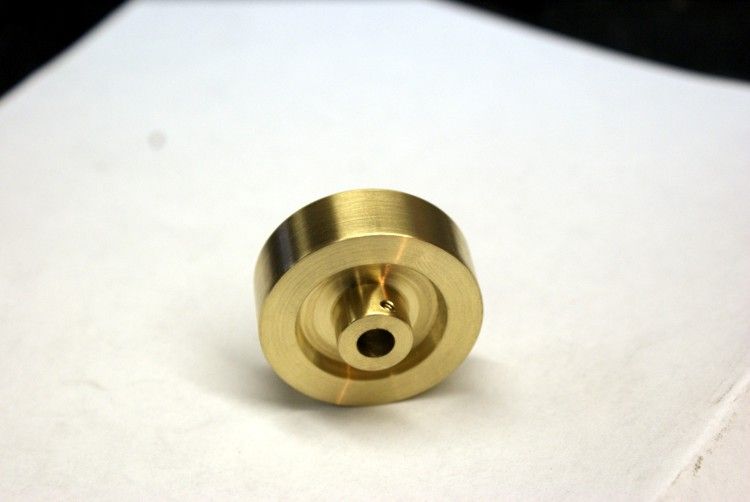
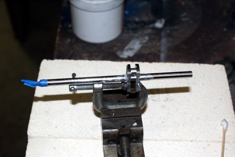
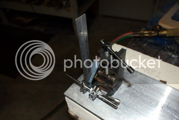
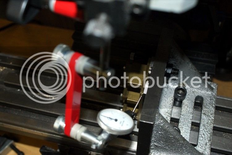
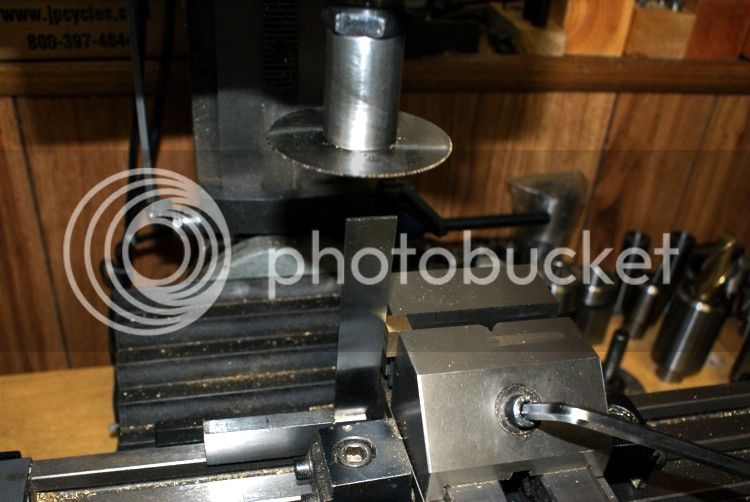
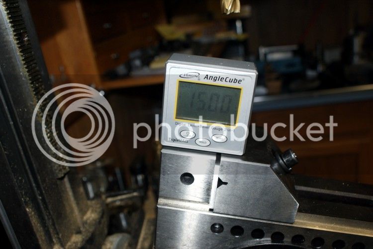
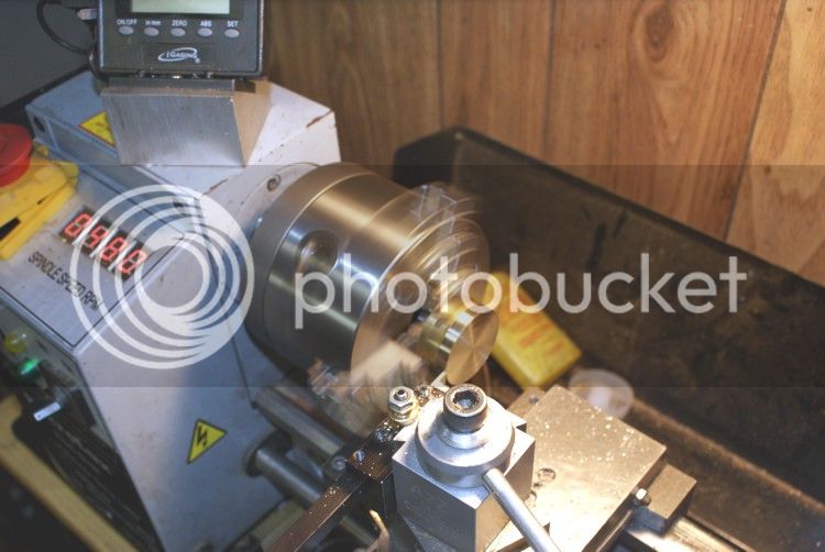
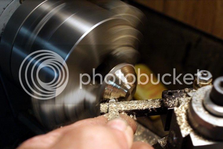
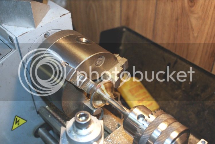
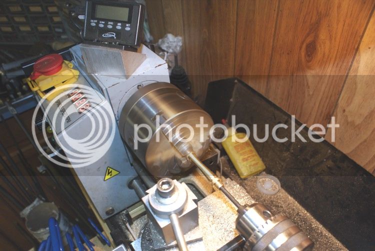
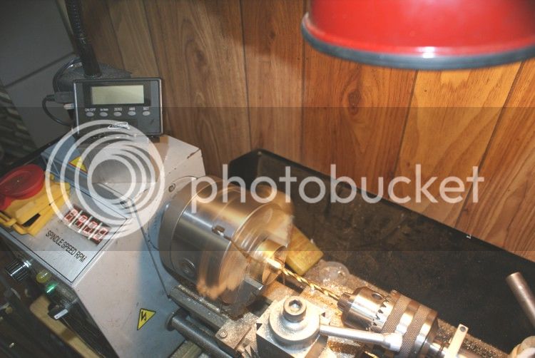
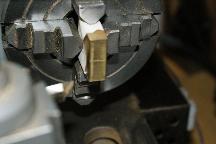
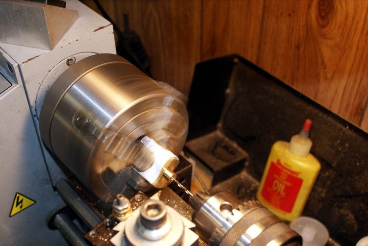
I will start by setting up the steam chest into the lathe and align it with the laser to the center punch mark and Boring and reaming.
NO1.jpg

NO2.jpg

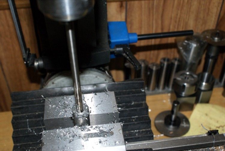
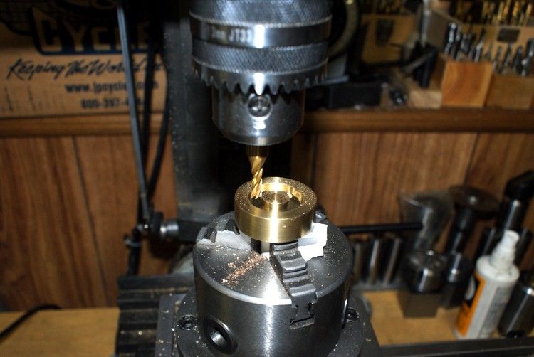
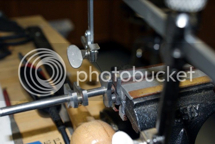
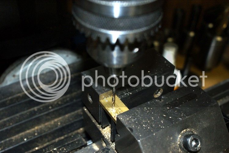
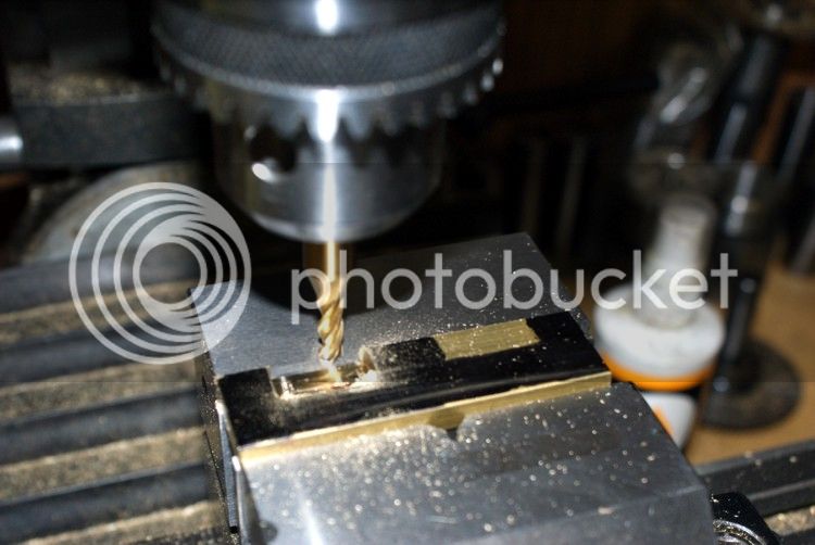
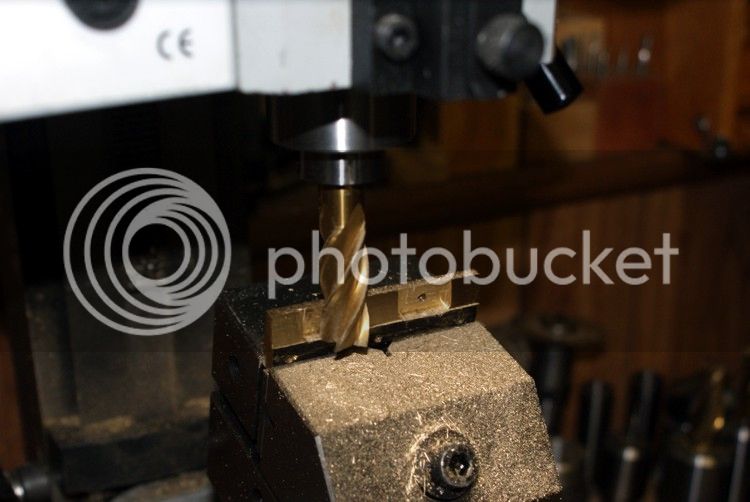
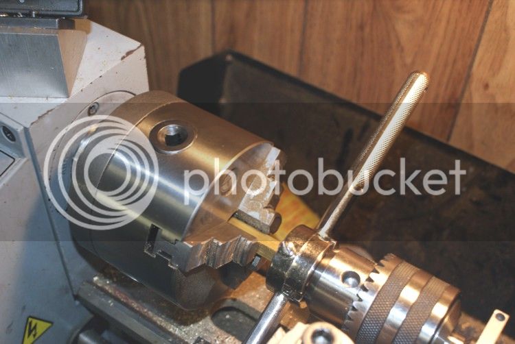
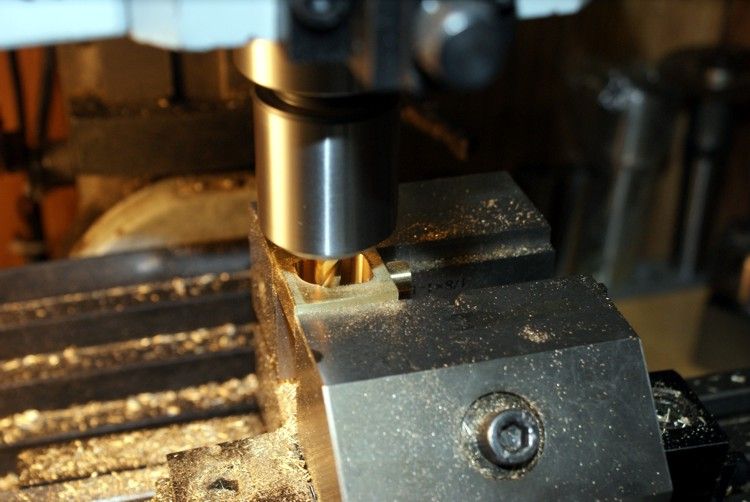
Now I set it up in the mill and mill the steam passage.
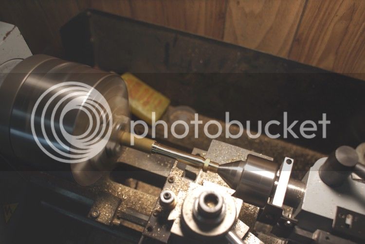
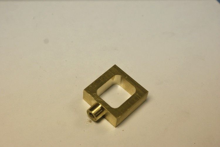
NO3.jpg

Milling complete
NO4.jpg

Will thats all for today

Don


Looking great Don. Im looking forward to following this build of a really nice engine
 
I'll enjoy seeing you finish this one Don. It is on my to do list.
 
Thanks guys for you interest. I will continue to post as I make progress, work is slow right now. Being summer it does not hurt my feelings any. I plan on making this a motor generator setup. I will be building a lamp post with an LED lamp for demo. All will be mounted into a Doll Case when complete. This is why I went with all brass and bronze. Below is the PM Research Dynamo I will be using.

Don


PMRESEARCHDYNMO.jpg
 
Well started off making the eccentrics and the eccentric straps. I used 5/8" cold rold steel for the eccentric. First off was to cut off a piece of stock big enough to make two. Then to the mill to drill the shaft passage in the eccentric. I set it up in the mill vise and used my coaxal indicator to center the mill. Then move to desired measurement and drilled through. Next was to move to the lathe and chuck it into the four jaw chuck. One thing I did wrong on the start was to cut the groves in the eccentric first in the three jaw chuck and then chuck it in the Four Jaw chuck to cut the offset, big mistake I cut the eccentric to size and then chucked it. The photo below is what happen to it.
NO10.jpg

Now to the new setup and doing it proper. First I center the shaft passage with the coaxal indicator and cut the offset then set up to cut the groove and then use the cutoff tool to remove it from the parent stock.
NO6.jpg

Drilled and Ream
NO7.jpg

cutting the offset
NO12.jpg

The eccentrics complete
NO13.jpg

I started the eccentric strap with a piece of 932 bronze stock chucked in the three jaw chuck in the lathe cut and bored it to size.
NO14.jpg


That is all I got done today.

Don
 
I had some time in the shop today and managed to get some work done. I started off by completing the Eccentric straps. The Flywheel was next in line and was cut from a 1 1/2" 360 brass round stock. I started cutting the resection and hub side and then drilled and reamed to 1/4". Then I rechuck to the oposite side to cut about a .125" resection on that side. After I had completed the turning process, I decided to add a little more to the flywhee. So I installed my rotary table and using an endmill cut eight holes around the inside perimeter of the hub.

The completed eccentrics and eccentric straps.
NO30.jpg

The Flywheel is beginning to take shape
NO22.jpg

Reaming the 1/4" shaft hole.
NO23.jpg

The completed flywheel and I decided to add some holes around the inside perimeter.
NO24.jpg

Using the rotary table to drill the holes
NO25.jpg

The completed flywheel finally and I believe I like that better
NO26.jpg

I will continue this on a new post.

Don
 
It's looking good Don. I like the flywheel.


Looking great Don.

I'm here till the end.

Ron
 
Next I decided to drill the holes to install the cylinder top and bottom covers. I installed my vise and mounted the cylinder block on the mill. using my edge finder located the top and left corner and using my DRO to drill and taps the holes.
NO18.jpg

The bottom cylinder cover.
NO17.jpg

I also completed the steam chest and covers in the same setup.
So having more time to kill today i decided to start the crankshaft. I had been dreading to silver braze. Fear comes over me every time I think of it. I have silver braze before when I wound motors years ago but that was copper wire. So here is my take of brazing. I set it up in a small vise I had and made a piece of 3/16" brass shim and clamped the crank webs to keep them at the proper distance. I like to soak it good with flux.
NO31.jpg

Well the first crank web and really is not to bad jst trying to get my confidence up for the next one.
NO32.jpg

OK first step I have to square this thing off. So I set the first square point.
NO33.jpg

Next the second square point and i had to flip the vise over to its side for this one.
NO34.jpg

I decided to use my jewelers saw to cut the crank web openings.
NO35.jpg

Ok that ws not too bad and the crank is complete.
NO36.jpg


Well thats about all for today and I will try tomorrow to have more.
Ok I had a photo of it partial assemblied and I decided to post it.
NO27.jpg


Don


A karma from me for the use of the jewelers saw! A very underated tool that can be very handy!
Looking good Don!
Dave
 
Dave thanks for the karma and your comments.

Brian and Ron thanks for the interest in my project.

BTW I sandwiched paper in between the bearing and installed and squared them to the bedplate. I started out by setting up the bedplate and bearings on to my angle plate and DTI them in the vertical side. After securing the bedplate to the mill I used my edge finder to located the top left corner and dialed to center point on the first bearing. I center drill the top bearing but do not have a center drill long enough to center the next bearing in line. So I used a half size drill to drill all bearings and finish with the last under size drill bit. I then reamed with an under size reamer and finished with the final size reamer.
NO37.jpg

Making the first pass through all bearings
NO39.jpg

Reaming the bearings to final size.
NO40.jpg

I then install the crankshaft and connecting rods and install it on the lathe to break it all in.
NO41-1.jpg

While I had the engine on the lathe running on low speed I started to mill the slide valve body the photo is only the start of the process I got carry away and forgot to take more. I just line it up to cut the slit down the middle of the valve body.
NO42.jpg

Next I started the steam inlet manifold by milling the flanges out.
NO43.jpg

Using the slitting saw to cut the flange to size.
NO44.jpg

Here I am bending the Manifold tubing with my micromark bender. I first fill the tubing with glass beads to pervent it from crushing the tubing. ???
NO45.jpg

Setting the manifold up for silver brazing. Oh!! a lot of flux. Thm:
NO46.jpg

Not to bad for a beginner. ;D
no48.jpg

And the manifold all cleaned up. As I was cleaning the manifold up, I decided to polish it. Well that was almost a big mistake. Thinking I had it in my hand securely and buffing away it went flying and I held my breathe :wall:. I was lucky today is all I can say.
NO49.jpg
 
I've never soldered anything in my life, it always amazes me when i see the photos like your last two - something so ugly can become so pretty and nearly flawless...

keep up the good work, watching every step!

- Ryan
 
As I am sure Don will agree...no real magic there Ryan.
Just patience, and hard work and some good planning.

Nicely done Don!

Dave
 
I appreciate the ovoid shape you put on the mounting flanges Don, nice going Thm:

BC1
Jim
 
Jim, Ryan and Dave thanks for you comments and interest I really appericate you guys watching.

BTW
Well I had another day of playing and today I decided to give the engine a pair of shoes. Ruby design this engine with just to bedplate but it just don't look right so here we go. I started out with milling some stock to 3/4" x 1/4"diameter.
NO50.jpg

I then wanted some mounting bolt holes and mill some opening about .125" deep by 3/4" wide to match the bedplate.
NO51.jpg

Just having the opening in the sole plate was not quiet good enough so I mounted my Sine vise on the mill and using my angle cube set it up for 15 degrees.
NO52.jpg

NO53.jpg

Here I am milling the angle.
NO54.jpg

after fitting the shoes to the engine here is how it looks. The engine is not complete as you see it I still have a few thing left to do to it. I am waiting for some 2/56 taps to come in. I managed to break three of them on this engine. One I dropped and it broke when it fell and the other two while tapping. No I don't have any excuse why just get too careless thats all.
NO55.jpg

NO56.jpg

tomorrow is another day so I will try to have more progress.

Don
 
Today I started out to make a lamp pole. The photos below show the progression of the built. I started with a piece of 1.5" 360 round brass to make the base assembly with. In the turning process I had some pratice at graving. I had done some graving before, but needed more practice. I also had to make a bending fixture to bend the tubing with. After I had brazed and clean up the lamp pole I set everything up on the MFB which came with the Doll case to get an idea of how everything will look.
First process making the base unit.
NO60.jpg

http://i1247.photobucket.com/albums/gg629/don1966/MARINE%
20ENGINE/NO61.jpg
Some graving with the end of a file.
NO62.jpg

Tapping the completed base unit
NO63.jpg

I then started the pole shaft by tapping the treads to screw to the base unit and center drilling.
NO64.jpg

The pole column is starting to take shape.
NO65.jpg

Almost complete
NO66.jpg

Made the jig to bend the lamp pole head, first I filled the tubing with glass beads then bend to shape without crushing it.
NO68.jpg

Starting the lamp cone.
NO71.jpg

More graving practice to cut the funnel opening.
NO72.jpg

Setting up for silver brazing.
NO73.jpg

NO74.jpg

The pole complete
NO76.jpg

The setup with engine, Dynamo and lamp pole.
NO79.jpg

NO78.jpg

I am still waiting on taps to complete the engine but I will continue to mount everything to the platform. I will post as I progress.
One thing I want to ask everyone is, what color to paint the Dynamo so it will match everything. Are do I just leave it as is.
Don


Don, Thats very nice work. That lamp pole is fantastic.

As far as what to paint the dynamo, myself, I would leave it as it is.

What ever you decide to do I'm sure it fit the theme.

Ron
 
Wow the light pole is a work of art!

The engine is pretty darn nice also.
Thanks for sharing your build with us.

Dave
 
Back
Top