Re: First Engine No Plans.

Home Model Engine Machinist Forum

Help Support Home Model Engine Machinist Forum:

This site may earn a commission from merchant affiliate links, including eBay, Amazon, and others.
Status
Not open for further replies.
HI
Well that was a long seven days! Spent most of it on the same job turning disks from EN1A 12 inch OD 10 inch ID 1/2 inch thick all to +- .0005. 30 of the sods.

I like to know what im making or atleast what the parts will be going too but some times it just dont get found out. MY best guess after a week of them was hoola hoops for midgets! But why would small people want half a thou on their hoops?

How many jobs do we do that never get explained to us? Wouldnt it be nice if at the bottom of teh drawings just next to the "checked by" box there was another box telling us what the job would end up doing.

On the plus side I managed to save some decent odds and ends for boiler plate formers so all's not lost.

Well im done for Hoola hoops and onto hitch pins next week so atleast I know what im making.
Ah plus im one step closer to buying a full size portable of 2nhp so life really is looking up!


Cheers and have a god weekend Kevin
 
HI

Well after a bit of a break for other work its time for me to extract the thumbs and start the soldering on the boiler.

Firs job is always soldering the throat plate to the boiler barrel. The throat plate is the forward most of the boiler plates and effectively forms the most important jont on te boiler. As the boiler barrel is the chassis of the engine it can be seen that the joint between the throat plate and the boiler tube comes under a lot of stress both compression and extension. For this reason its important to build up a good fillet of silver solder and ensure perfect penetration of the joint.

As always in silver soldering it is most important to have the copper as clean as is possible. This will always involve pickeling in the sulphuric and then rubbing with wire wool. As soon as the copper has been wire wooled run a bead of flux around the clean copper in the location you want the solder to flow.

Settng the assembly on a few fire bricks check that the tube is square on to the throat plate. Once your happy that the plate will go on in its correct location run some more flux around the joint. At this stage cut short bits of silver solder maybe ¼ inch and cut enough to go all the way around the joint. Lay the cut solder as close as you can to the joint and dab some flux over the solder.

Given the size of the tube im soldering here 10 gauge 5 inch OD tube. I will have to add a lot of heat from the inside of the boiler tube. The easiest way to do this is to fill the tube with charcoal to about 3 inches above the joint that’s being soldered. As the boiler is standing on its throat plate end during this soldering stage once the charcoal is alight it will tend to use the upturned boiler as a chimney and draw rather a nice fire. Along with the two propane torches this will give more than enough heat to solder the joint.

At this point il admit I forgot to take pictures of the joint being made. Most of the following joints are done the same basic way but still I wish I had remembered.
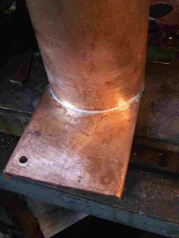
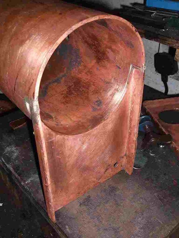
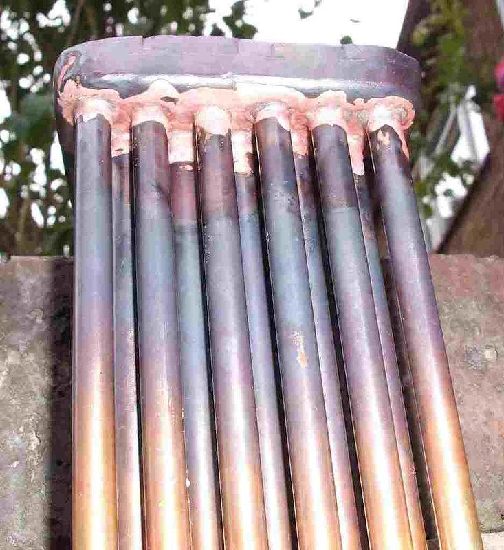
These to pictures show the finished joint with a good fillet on the first picture and full penetration on the second image.

9.jpg


10.jpg


All that’s required after the joint is made will be a lite run in the acid to pickle off the flux from the joint. Before the outer wrapper is put on the flahges will be pickled and poished once again.

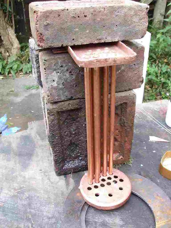
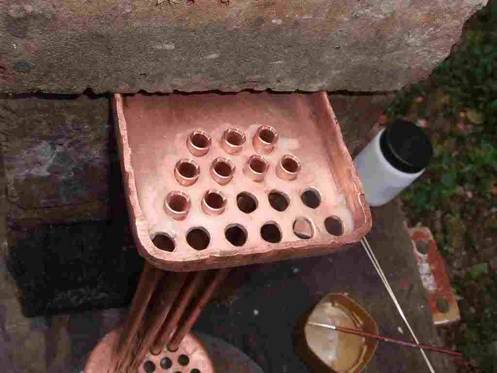
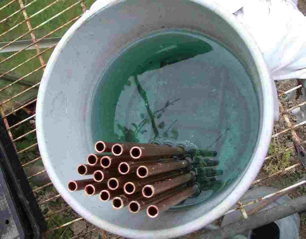
So onto the next part of the build, the tubes being put into the firebox tube plate.

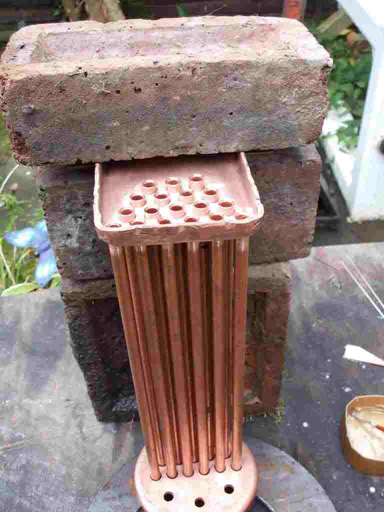
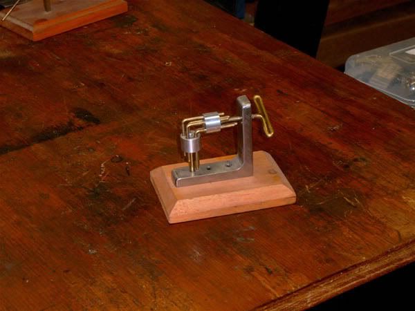
Possibly the hardest part of this job is finding ways to hold the boiler oarts during the soldering operation. As can be seen from the first image it can be a bit of a lash up but as long as the job is held well and safely go with what works.

1.jpg


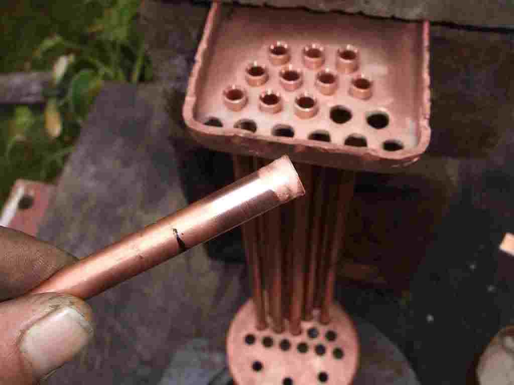
As each tube is placed into the pickled and polished tube plate the tube is polished in the lathe with sotch bright for about an inch up the tube from the joint.

3.jpg


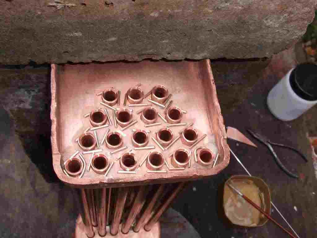
Also the tube plate and tubes are fluxed as each tube goes in.

2.jpg


Once all the tubes are in and ready just run a little extra flux around each tube to be sure and safe.

4.jpg


Setting the silver solder on in short bits lets you surround each tube and almost flood the tube holes as soon as melt is achieved. Heating should never be directly onto the silver solder. It should melt from the heat of the metal rather than the flame. This is the best clue that a good hot joint is being formed. Also the solder will flow towards the heat.
Rodding a little extra solder on is fine as long as again the melt is caused by the heat in the metal rather than the flame.

5.jpg


Start by heating the tubes slowly bringing them up to the point that the flux bubbles and dry’s out. Never play the flame directly onto the wet flux it will tend to boil the flux away from the joint.
As the assembly starts to turn from clean copper to black you know the heat is enough to get seriouse. At this point I start the second torch and heat all around the underside of the joint. Try to play the flames in between the tube and keep moving all the time so as to heat evenly.
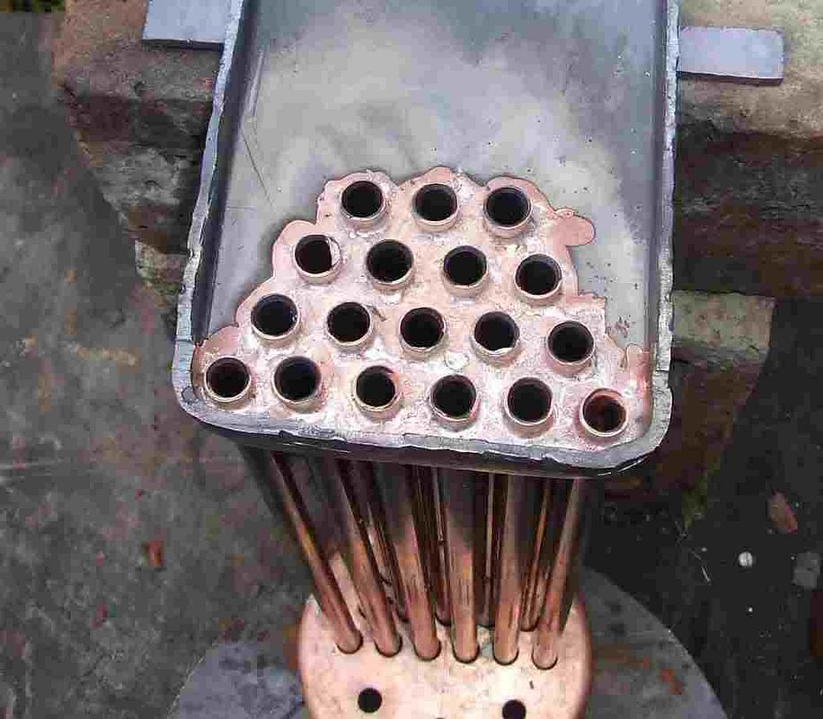
As soon as the solder starts to melt watch the way its flowing if it seems to be flowing away from the tubes get some more heat into the tube cluster. Once the solder is fully melted and has flowed through the joint check to see if any extra rod is required. It almost always is.
As soon as you see a good fillet around all the tubes cut the heat and sit back. I have a smoke and a coffee till the bits are cool enough to pick up. This is the time to again pickle to remove the flux.

6.jpg


7.jpg


In the acid

8.jpg


Next job will be the firebox wrappers and fire hole ring, lots a heat and swearing on this one.
I wil try to upload the next part Wednesday this week.

Cheers Kevin
 
HI

Just as a fill in between posts I thought I would give some idea of the amounts of solder flux and gas thats required for a boiler this size.

Silver solder.

The only one to use on boilers is Easyflow 2, BS EN 1044, AG303. the composition is 42% silver with cadmium.

The flux must be a dedicated flux for this solder and one designed to stand long brazing jobs. Borax on its own will NOT do the job.

For the boiler im doing here I have ordered 60 1.6mm rods and 15 2 mm rods. I dont think I will have more than a few rods left over at the end of the job. If you think you will want 10 rods order 20 and you will be close.

Flux wise Il use around a pound and a half. When im mic=xing the flux into a paste i add a tiny drop of dish soap it helps the flux paste and wet the surface of the joints.

Gas wise il use 1 2.5 KG cylinders of propane and a few smaller cylinders for the Bernz-O-matic torch. The acetalyn i doubt will even register on the bottles as used. The 50mm Sievert will use most all of the large cylinder in a few sitings its a really hungry torch.

Dont go to the point that the boiler is all silver solder but the joints must be fully made and no voids can be in the joints.

Cheers Kevin
 
Have just noticed that my entry to the introductory page is immediately after a "viagra salesman" post. I solemnly swear that this had nothing to do with my entry in the forum and besides, regardless of my physique, I am married to the same woman for 40 consecutive years, whatever it means to you.
If I mistakenly touch her at night, my hands are too cold if winter, or too warm in the summer.

George
 
Sometimes I think that getting an engine, particularly a complex one like that, to run for the first time produces an endorphin high that must rival what all the druggies are getting in a far less innocent manner.

If the medical community actually understood the therapeutic benefits of building something, we'd have enterprises where one could walk in and rent time on a lathe next to every gym where one rents time on a treadmill to produce entropy.

Great work, Mogens. Keep it up.
 
When I first found this forum the Elbow Engine grabbed my attention right away because I built one several years ago and could not get it to run. A few years back I took another look at it and built a new set of pistons and new cylinders to no avail. With many hours of "playing" with it the fascinating monster still failed to run or even turn over when air was applied. All the posts about the problems several people are having with it do help make my failure a little more tolerable. Home Shop Machinist magazine had a right angle drive of the same principle several years ago, (my Dad told me there was one running a lineshaft drive in the family business when he was young) so I made one with 5 rods (10 cylinders) that was hand operated and it worked.
S3500002A.jpg

Don
 
Well, I haven't had very much time to get out to the shop these past several weeks. I am building a finger engine for a friend as a trade for some sound equipment. This is the second finger engine that I have built, the first being a Saturday afternoon goof around project and not very well finished. This one I am making much nicer, and will mount it on the Oak base. A few more pieces, some polishing, and this one will be complete.

100_0435.jpg
 
Steve: They were just discussing this on Harry's old Engine Forum Site----Smokestack, in the Antique Engine Discussion section yesterday. They even listed a fellow in Kentucky that evidently has or sells the plans and there are some pictures. If I remember correctly I saw a model of it at the GEARS show in Portland OR. last year. Possibly it will be there this year also, on Saturday, if I can get close enough I will try to get some information.
Don
 
The designer of the engine that is the subjecxt of this thread is Jan Ridders.

Jan is a member of a number of Yahoo groups and is always very keen to assist people working to his designs. It would be a good idea to contact him if you are working on something from his site as he is a mine of information. A trawl through his posts at the Yahoo group 'barstockengines' would be a good start.

Ian.
 
Hi
This is my all day lathe its a Colchester 800 flat top. No gear box but plenty of change wheels. It runs three phase 415 volt as do all my machines. If i had to pick one to keep this would be it. For ease of use it beats the Dean Smith and Grace hands down and is a better height than my Harrison.

bantam.jpg


cant praise the Colchesters enough.

Cheers Kevin
 
Macona

Monarch will still make you a lathe from new castings.

At least last year they had eight new beds cast up for one contract.

Hal
 
Hi,

I disagree with the suggestion of always buying High-Speed Steel taps instead of Carbon Steel.

Any debate about the prefered material for taps needs to consider the use or application of the tool - industrial requirements are very different from the needs of the keen amateur.

As a basic material CS is harder than HSS but cannot be used at such high working temperatures. Taps in an industrial tapping machine can get hot enough for this to be a problem but this issue is of no concern when tapping by hand.

As CS is harder than HHS, CS taps will remain sharper for longer which means you won't have to replace your taps so often (unless you are in the habit of breaking them - which is where this thread started........)

But more important than the material is the way CS and HSS taps are made:

CS taps have their threads cut while in a soft state using a master die, the flutes are then cut, then the tap is heat treated and finally sharpened. The heat treatment process will always give some slight distortion to the tap which effects its straightness - this is important if you have a tool and cutter grinder and want to re-sharpen your taps (I have to admit that I'm not in this league and just buy new taps when they get blunt).

HSS taps are made from hardened blanks and the thread is formed by grinding. This is a more accurate method of manufacture and results in the centres on the tap ends being truly central to the tap thread. This allows the tap centres to be used in any resharpening process (of course, most of us grind off the male centre on the bottom of the plug (bottom) tap anyway). The increased accuracy of the thread may be of interest if you are making micrometers, but for normal use it makes no difference at all.

Given the above, in my opinion the only real factors to consider are:

1) Cost - HSS taps are between 1.5 and 2 times more expensive than CS taps (in the UK)

2) CS taps remain sharper for longer.

3) If everything goes horribly wrong and you break a tap and none of the usual 'tricks' can remove the jammed tap fragment, CS can be softened with a reasonably small amount of heat allowing the remains to be drilled out.

In view of this I go for CS taps and dies.

Ian.
 
Hi Hilmar,

Please take a look at the back of the chuck...... Is there a lathe attached to the backplate? If so, I would be interested in taking it off your hands.

Ian.
 
Steve: Just got back from GEARS and did in fact see the engine you were posting about (along with many, many others). We were there when several exhibitors were gone to lunch but I did get to snap a picture between shoulders and heads getting in my viewfinder.
S3500039.jpg

I do not know much about this engine but Henry must have refined it quite a bit to be able to operate a horseless carriage with it.
I am glad you found the producer of the plans and are on your way to obtaining them for your enjoyment and hope to see the product of them at some future date on this forum. Don
 
Hi people,
one of my best (and usually free) source is the odd caput printer that some friend is ready to throw into the garbage can or somebody already has, if I am lucky.

Lots of straight steel rods thin plates, springs e.t.c. can be found.

George
 
If you get a chance to read some of the excellent books by Kozo Hiraoka (Shay, Climax and Heisler live steam) you will see that he advocates the "small piece of solder" method. As his photos show, it does a VERY neat job.
 
I found this site has some really good scans from old magazines. No plans but great pictures. Much of it is Sea Fury.

http://www.pfs-ware.com/smith/MyPage/MyPageToys2.htm

I bought a box at auction last Saturday. $5 for a half -finished balsa plane and a box of dusty props, 6 dirty old airplane engines and ...
a Sea fury outboard. More projects to store in the garage.LOL Outboard motor is pretty gummed up and no glow plug or transom clamps but way cool. Sorry no photos yet.
 
Hello All: I apologize for taking so long to respond to the comments about the little engines. The four cylinder engine has a static inlet/exhaust divider in the horizontal "axle" at the sealed end of the cylinders. There is a rotating spider that has ports to allow the air to go out to the pistons as the opening rotates over the opening at the divider. Hopefully the picture of a sketch will be clear enough to show what happens.
S3500004Y.jpg

S3500006.jpg

The next picture is of a couple of a Rudy Kouhoupt designed oscillator engine (1969) that my son and I built for Christmas presents about 10 years ago for his "Grandpas".
S3500005.jpg

A oscillator made with square tubing and no lathe needed probably came out of Popular Mechanics or Live Steam Magazine.
S3500003Z.jpg

Thanks for looking. Sorry about the dust, please don't tell my wife. Don
 
After seeing Don's "Swash plate" engine, I remembered that I had marked a web site with one very simular. It’s called the Green Steam Engine and uses a method of converting reciprocating movement into rotary movement. I tried to reproduce it once, but got lost in other projects that my wife thought more urgent. I think I still have the parts I made.
IF any of you want a look, here is a link to the site.
http://www.greensteamengine.com/
there is even a video of it running.
I may have to take another whack at it.
Mel
 
Status
Not open for further replies.

Latest posts

Back
Top