Re: First Engine No Plans.

Home Model Engine Machinist Forum

Help Support Home Model Engine Machinist Forum:

This site may earn a commission from merchant affiliate links, including eBay, Amazon, and others.
Status
Not open for further replies.
Hope I have this picture thing figured out. This is a late 60's/early 70's EMCO Maximat 10v-P. P stands for power x-feed. When I acquired the previous owner used it alot for wood work and it was thick in grease/oil and sawdust that did not want to come off easy. Still have some cleaning to do before I'm satisfied.
Julian

V102.jpg

V101.jpg
 
Hi
Im new on this site but having just added another RT to the tools thought id jump in.
I bought a second hand Kamkura RT 12 inch D. Have to say im now looking for another in 18 inch its just simply a really nice table. smooth as you could wish for and as solid as a rock.

Cheers Kevin

[/img]
 
HI kenny
Not sure about small RT's as my smallest is 8 inch and my largest 18 inches.

that said theres a program on a site that will convert for you and as far as i know its free to download.

The other RT id seriously look at is the Vertex. absolutly fantastic quality and not bad money. I have a ten inch tilting and wouldnt swap it for Kylie Manogue.

il try to find the link.


Cheers Kevin

Well ok yes i would swap it for Kylie
 
Hello John

I did the tescos run on the 1 inch again this time t keep my friends daughter happy. She's 8 and seems to have a good talent for driving the engine.
All sounds like a big adventure but tescos is 500 yards on flat ground so its not a bad run.

The two inch is coming on well after a delay for health, work and family.
Had the drawings come for the next engine Friday. Im going to have a try at the 5 inch Foster rope hauling engine. Rather like the idea of a chain drive single gear with no reverse eccentric. (may add a slip eccentric to make life a bit easier)

Did you make the journey to Dorset?

I have to say the guys on scale models are a good bunch. lots of enthusiasm and some good ideas.

What are your main interests?


Cheers kevin
 
I have the entire set of Popular Mechanics books printed in 1955 also the year that I was born. They have many machining subjects in them. There are 12 books in the set, 13 with the index all in beautiful shape. I bought mine at a garage sale, had to dig them out of alot of other books. The lady wanted a dollar a book which I would have been happy to pay once I looked through a few of them. She even brought me a box to put them in and then only wanted 5 bucks for all of them, she said it would be 13 books less to pack away. I gave her 15 bucks for all. Best set of books I ever bought besides the 1945 12th Edition of Machinerys Handbook for 10 bucks I bought 2 weeks ago. Pete
 
Hi

I dont tend to make spare parts for my engines on the basis that if i get a broken part it has broken for a reason and needs a redesign.
The only parts I do make spares of are eccentric sheaves and always just one.

Mind you I some times wish i had a spare set of wheels for the traction engines for those hours of cleaning after a run!

OOH and a spare coal shovel would be a nice addition seem to loose a lot of them. last one went in the firebox followed by my friends daughter laughing at me. (full size Fowler)

Cheers Kevin
 
HI
Best way i know to center work ina four jaw is using a floating center mounted between the center in the tailstock and the center drilling or center punch mark on the job. Now just bring a DTI in on the floating/wobeling center and adjust the chuck till the run out is as close to zero as you want or need.

Dont need to say do this with the power off do I LOL

Cheers Kevin
 
HI
Polly models in the Uk do a curved cylinder steam engine. I know for one reason my brother built the swine!

Its a fantastic engine to watch and a real interesting design but the curved cylinder was enough to turn me to smoking ( oh blast I already do)

In all honesty it wouldnt have been too bad if we had more time for the build.

cheers Kevin
 
The curved cylinder was machined full size using a horizontal boring machine and a large rotary table. In the model
the curved bore was machined using a metal jig that was pivoted on the back of the cross slide. An extension being
bolted to the back of the cross slide to get the pivot point far enough back. The other end was forked around the
toolpost on the top slide. The top slide being used to apply the feed to a boring tool held in the chuck. The cylinder
casting was clamped to the jig.

Hi Cedge

Thats the text from the Polly catalogue, but if memory serves we used teh bridgport and a 12 inch rotary table mounted verticle. As you say a boring bar with enough trailing clearance will do the job. Being a 19mm bore it allows a reasonable bar to be used

Not an easy engine but well worth the time.

Cheers Kevin
 
In the UK this is called a 'tangential tool holder' (because the tool is held at a tangent to the work instead of axially).

On larger machines the vertical adjustment of the tool is through the use of a screw that acts on the lower 'end' of the tool and this provides a micrometer height adjustment of the cutting tool. Usually, the biggest problem in using this type of tool on a small lathe is the lack of clearance between the lathe centre and the top surface of the compound slide.

I would agree with all that has been said by others in this thread - the fact that the tool acts in compression rather than experiencing bending forces makes it a very robust and forgiving setup.

Ian.
 
Hi
Yes do it on a semi regular basis but not by welding.

I cut the blade at 45 degree angles both broken ends then grind a taper on the angled ends thinning the blade to nothing. Doing this gives a large surface area for the braze to take on.

The jig for the blade has a ledge for the back of the blade to align on and an open section for the flame from the gas torch. Always heat the blade from underneath and use the heat from the blade to melt the braze not the flame.

Two G clamps hold the ends of the blade to the jig and also wick the heat away stopping it traveling along the band.

Weld is not the way unless its resistance weld the filler metal will always fail.

Cheers Kevin
 
HI
try to not run like metals together if you can help it. if i understood you the bronze shaft in a bronze bush would be better as a stainless steel shaft in a bronze bush.

Stainless steel machines ok just tougher

Cheers Kevin
 
I've been working in mostly job shop machining for 30-some years. Most places have been low tech machine pieces, sprockets and such. One shop had close tolerance and exotic material: titanium, tantalum and pure moly. I mostly ran engine lathes, big or small. For a while I did G-code programming and milling of aluminum die cast molds. We made many parts for Big 3 automakers. Now I program and run 5" G&L bar with FANUC. I like machining because of the skill and talent that shows when a job is well done. Model building really piques my interest, for the quality of workmanship, you guys are AWESOME! Like many of you, I love to figure out how and why things do what they do.
I own a Chicom 7X10 lathe and HF $39 drill press. Need to get a mill at home so I don't have to hang around at work after hours. Then I need to buy tooling.....
 
Where I was working the drafting department decided to get rid of the microfilm reader machine. I asked if I could have it, and was even helped to move it out to the Lab where I worked. It was too big to haul home in my "74" Pinto so I took it apart at work and kept anything that looked like a part of some future project. There sure was a lot of small bearings and several shafts and rollers, mostly all metric, but I can always order metric rods to use on a model. The base cabinet ( my assistant helped me get it home with his pickup) is now a roll around table in the garage with a 3/16" steel plate on top that is great for a welding table, and tools are stored below in the cabinet that stored the paper and drive controllers. A scrap metal yard was close to my way home from work that had a brass section, a aluminum section and a yard full of assorted steel. The prices were not very low but you could buy small pieces and save that way. They have changed to mostly steel scrap now so I guess it's time to check out some machine shops.
Don
 
Just a quick one this time mostly due to time and it being Sunday evening .

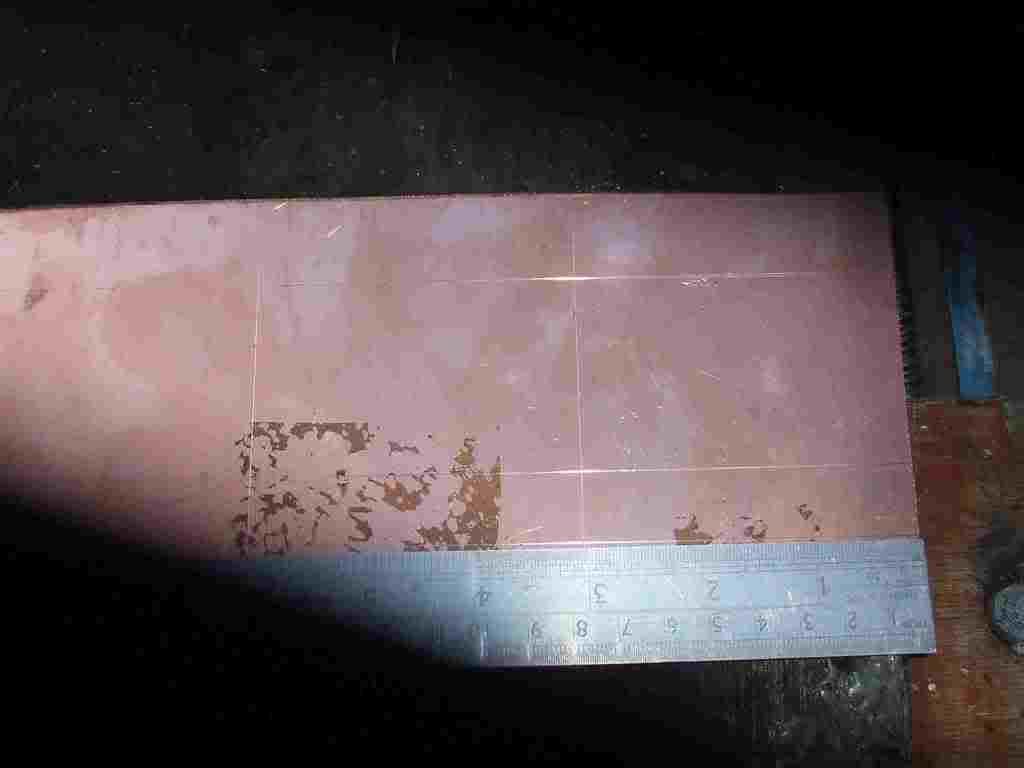
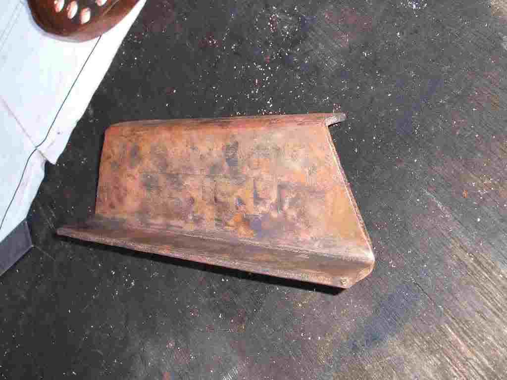
After the outer wrapper you then have the inner wrapper or firebox wrapper to make. In a lot of ways its an easier bending job than the outer wrapper being parallel sided and flat topped. The only problem is the rather tight bends to fold round to the crown.
The top of the firebox is called the crown.

fireboxwrapper1.jpg


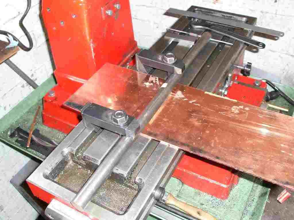
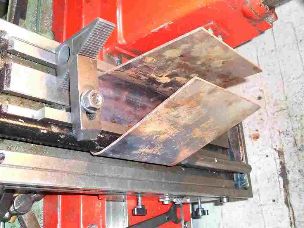
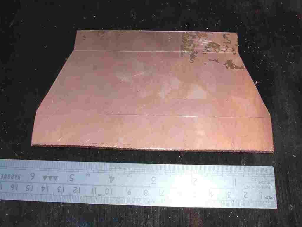
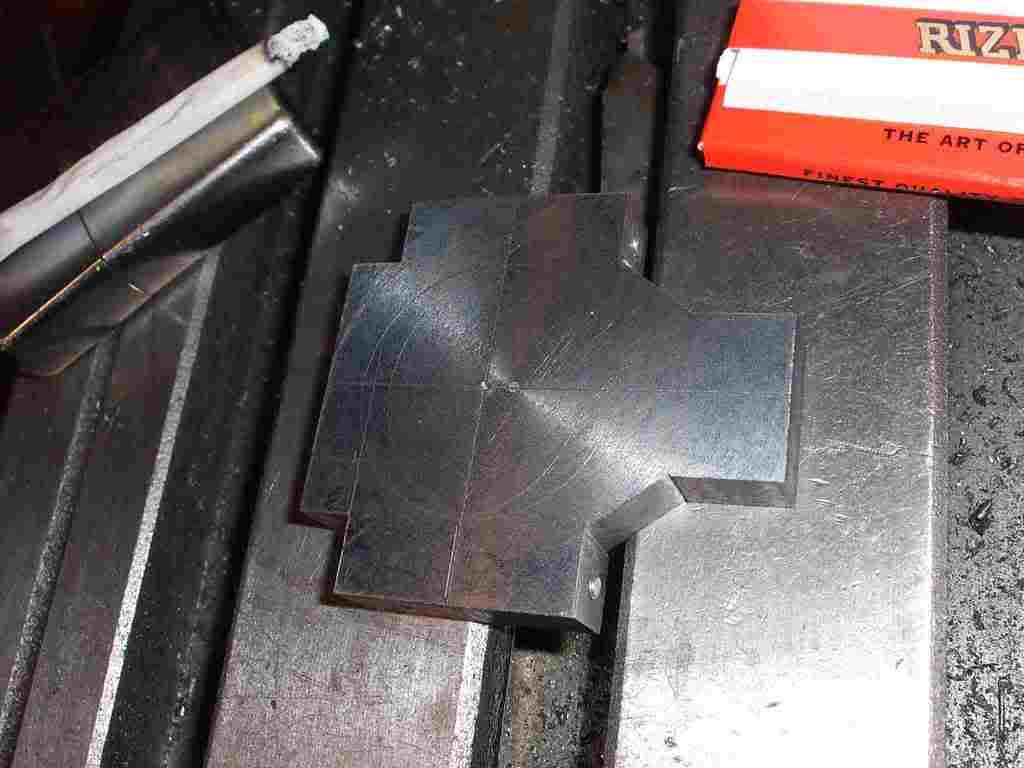
The way I like to do the firebox wrapper is by using the milling table on the mill drill and a 1 inch steel bar clamped over the wrapper sheet. Thanks to the gauge of copper a rather long bar is used as a lever to help the first bend. In this case three feet of ¼ x 1 3/8th MS.

fireboxwrapper2.jpg


Before starting the the second bend the first must be a perfect fit on the firebox end plates. If it is not a good fit the second bend will be in the wrong place and a lot of fiddeling will be required to correct the problem On this not its always worth cutting the wrapper and inch over length just so a little wiggle room is there.

fireboxwrapper3.jpg


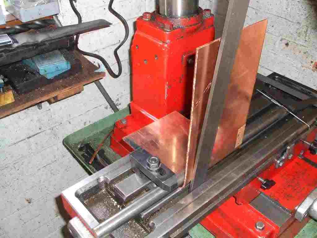
For the second bend I add a large square bar in behind the round forming bar for two reasons. Firstly it allows a better clamping set up and keeps the crown flat, in addition a line can be scribed behind the square bar as a reference should the form need to go in a second time.

fireboxwrapper4.jpg


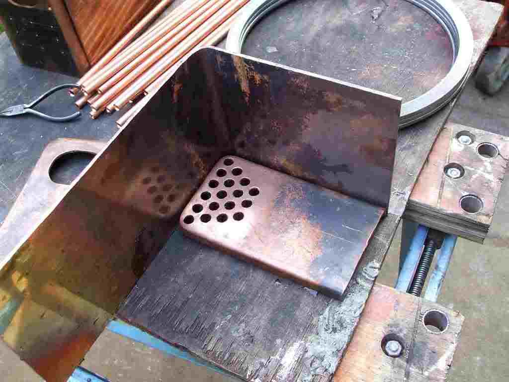
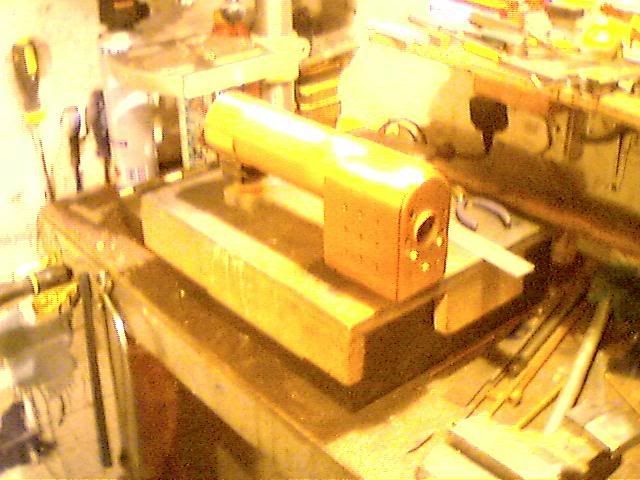
Once the second bend is in place the firebox plates are dropped in just to check it all and give me something to feel like im getting on.
In the large part the two wrappers are finished now. All that’s left to do is drill for the fusable plug and tidy up the bends just prior to pickeling and soldering.

fireboxwrapper5.jpg


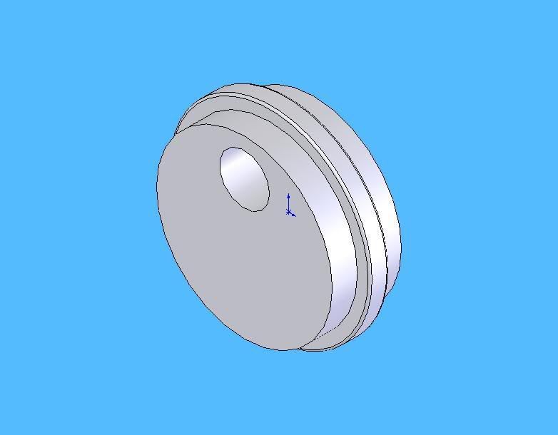
Next job is making the crown stays. Unlike the wrapper stays and throat/front plate stays the crown stays are on this engine made from again 10 gauge copper sheet.
The crown stays are in some ways the most important stays in the boiler, although none can be missed out either in the wrapper or the plates.
The crown stays fit between the firebox wrapper and the outer wrapper preventing the steam pressure from crushing the firebox or bulging the outer wrapper. And yes I have seen a collapsed firebox it was on a Durham and north Yorkshire in 2 inch. The crown had dropped almost a full inch and the joint ruptured on the tube plate to wrapper. Not a pretty sight and a full replacment boiler was required luckily the owner was left scared but Ok the engine was at 90lbs at the time.

The crown stays are a relativly simple job but must be with in 1/32 of the correct height of 2 and 3/32 inches. If the stays are too long the firebox will sit low and too short the firebox door ring wont mate up.

crownstay1.jpg


Bending is easy with plenty of annealing just clamp in the vice and fold over with a pair of tongs. Hammering the bend somewhat flat after. All in all each stay required four annealings to complete

Il let the pictures do the talking LOL

crownstay2.jpg


crownstay3.jpg


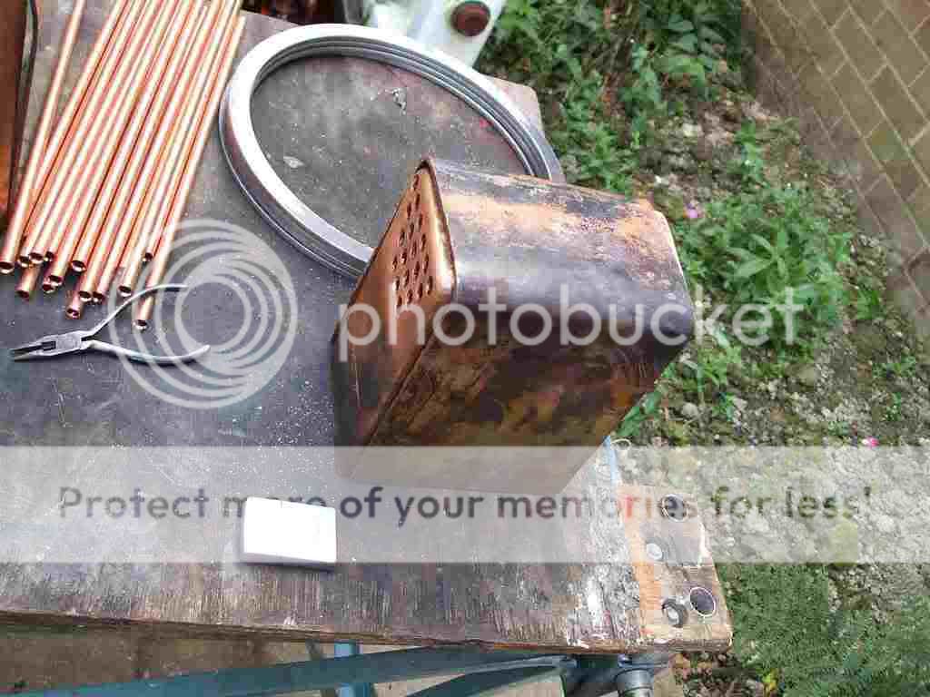
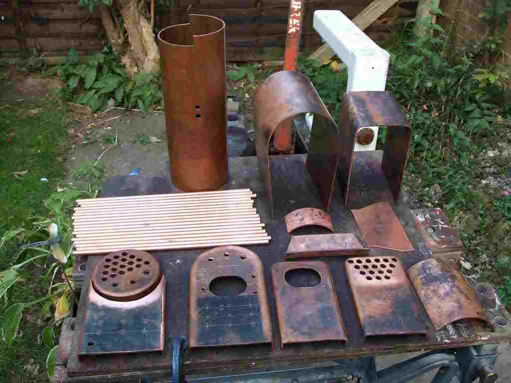
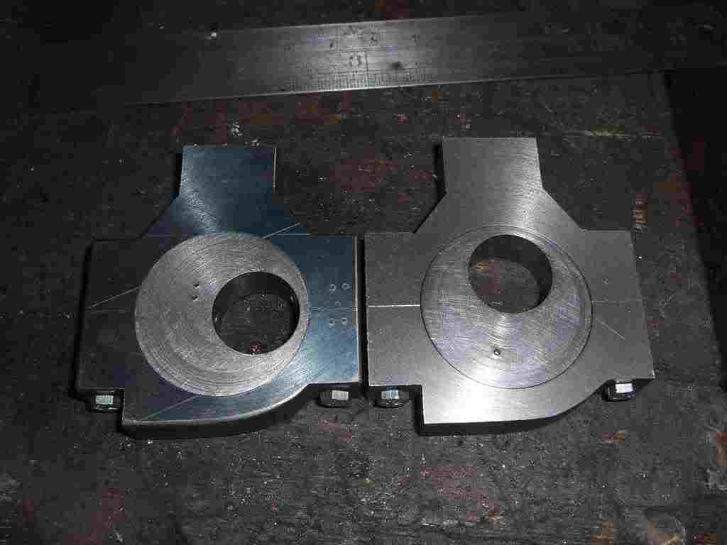
Just in passing the last picture shows all the boiler parts made to date.

pileofbits.jpg


Oops forgot to mention the cylinder pad and motion plate pad. If you look closely at the last picture you will see in the bottom rite hand corner and just infront of the outer wrapper two arched pieces of copper. These are the pads that are silver soldered inside the boiler tube to take the cylinder and motion bracket studs. Nothing special just two 10 gauge squares rolled to the inner curve of the boiler tube. More on these when the boiler is soldered together.

Cheers kevin
 
Hi Ken

The boiler thats being bilt is for the same engine as the one i posted before but this time twice the size or 2 inch to the foot.

backheadtwo.jpg


os.jpg


Il scan the boiler drawings during the week so you get an idea of the construction

and thanks for teh kind words, its a pleasure doing this feels like sharing the work load.

Cheers kevin
 
Hi
not sure if this could be used on smaller engines easily but most if not all the eccentrics i make use a center shoulder on the sheave and a groove in the strap

eccentric.jpg


If the sheave is mild steel and the strap cast iron i dont try to go better than a thou or so for the fit to get a good slop free strap. In addition making the groove 10 thou deeper than the shoulder it forms a gallery for the oil.

Cheers kevin
 
Kevin, Rick and all others: Machining seems to have been declining in the school systems for several years, but they are teaching computer skills and that could be a avenue into machining. My Son started in Engineering two years ago and one project was to design and build a oscillating steam/air engine out of the material the class supplied. The machine shop at the school must have been quite limited in number of machines so each student's "lab" time was somewhat hard to come by. His College was only about a hour travel time away at that time, so Eric brought his work home and I must say it really gave me the most fun in the shop I have ever had, guiding him to the correct tooling and use of the different machines. The finished product was not the most complex machine but they designed the drawings themselves and then made the machine from the drawings, that should give them a little sympathy for machinists in the future. This is a picture of the first try and RUN! of the engine.
S3500137.jpg

The engine won three of the four categories for grading of the engines in the class.
One thing I never expected to hear, (and am proud of) when he visited home from the school he is at now (Nashville) was "It sure is good to be somewhere there is a shop to fix things in." So--THERE IS STILL HOPE!!!
Don
 
HI
Well with most of the copper boiler parts cut bent and ready i thought it was time to mention cleaning the copper or pickeling as its known.

Copper to silver solder MUST be as clean as possible, thats free from any oxides and no finger prints. Even the smallest amount of grease or oxide can give rise at a later date to a boiler failing a test! its that important.

Common sense would have us pickeling every inch of the copper after every silver soldering job. The problem with this is you dont want the solder to run all over the boiler but just rather in the joint your making. A layer of oxide will act like a dam for the solder and keep it from spreading out over more of the copper than you want.

At most i only pickle half inch either side of a joint. With complex assemblies like the firebox and tube set this isnt always possible and the entire firebox has to be pickled ( rather a large lump to dip in acid in one go!). As a rule of thumb on most other joints keep the pickeling area to a minimum but make sure you have enough clean copper for a fillet to form if required.

OK SAFETY

Sulphuric acid will burn you even in a dilute state at 20%.

Sulphuric if mixed wrong will boil and spray up at you!

Sulphuric fumes are not to be breathed in and certainly not to be got on you!

Sulphuric will blind you it will not play games if you get it in your eyes you will not see the sunday football again!

I watched a huge miserable fitter sit and cry after burning the back of his hand with sulphuric! It really is painful its like no other burn your going to get and it heals really slowly!

Sulphuric is not the only pickle you can use but its the one i use the choice is yours but I take no responsability or do I recomend its use.

When you mix the sulphuric with teh water to dilute ADD THE ACID TO THE WATER AND NOT THE WATER TO THE ACID! be warned pooring water on acid will make it boil and it will be a bad day! I mix between 20 and 40% acid to water depending on the grade of acid and the weather. warmer weather less acid and vice versa.

keep the pcikle locked up when your not using it and nder no circumstance let any one play with or go near it its your responsability no one elses.

Keep a large bucket of clean water close by just incase. Youl also need a wash bucket filled with clean water change this every day. dispose of the waste in accordance with local regs.

Im sorry if this all sounds seriouse but in truth it is and I have had acid burns so im not talking out of my hat.

Once the pickle is mixed and your ready to clean your first two boiler parts. find yourself some rubber gloves and safety glasses. slowly lower the parts into the pickle and if possible suspend them using string and not wire. pickeling time will change with temperature and the age of the acid mix but in general 15 mins is long enough to clean all the rease and oxide off the copper.

Should you find a really nasty bit of oxide use Scotch bright NEVER USE EMERY CLOTH IT CONTAINS GREASE AND THE CARBORUNDUM CAN ATTACH TO THE COPPER.

As soon as the copper comes out of the pickle swirl it around in your rinse bucket and them avoid touching the pickled surface flux as soon as possible.

Wll thats about it for pickeling just be safe and again sorry for the strong safety bits.

Cheers kevin
 
Hi

Just machined the second eccentric thought a few pictures could be useful.

First one shows the eccentric split faced and the two half pop marks together making one to center the work on if split and machined well there should be no need to re pop the strap.

centerpop.jpg


next shows the floating center being used with the DTI to find the center. .0005 runout.

centering.jpg


Boring the strap with a 7/8 th two flute. RPM 82 feed .0015. Thats about a good set up for Mehanite.

boring.jpg


Machined strap in the four jaw.

machined.jpg


The matching pair of straps.

pair.jpg


Cheeers Kevin
 
Status
Not open for further replies.

Latest posts

Back
Top