- Joined
- Feb 17, 2008
- Messages
- 2,326
- Reaction score
- 440
For the most part I have been out of the shop for the past several months because of medical problems. Things are looking up and I hope to start a new engine before fall. This means selecting a project engine. I am down to two at the moment.
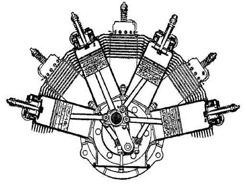
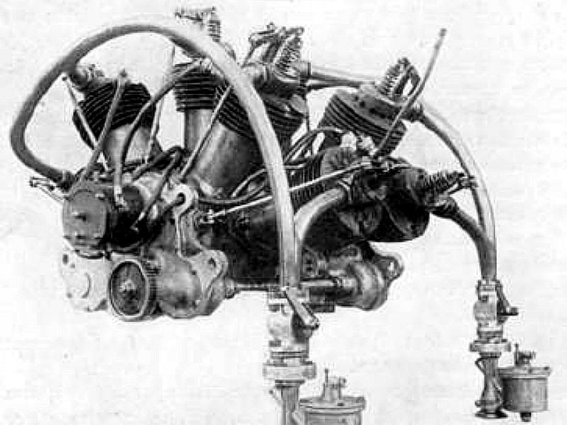
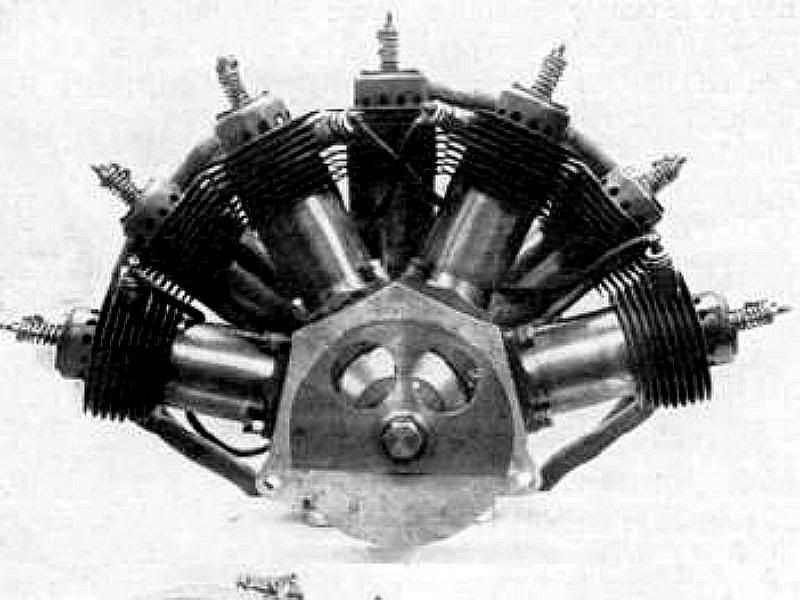
One of these is a 5 cylinder "fan" or semi-radial engine to be a look alike for the 5 cylinder engine built by Róbert Esnault Pelterie. He built both 5 and 7 cylinder engines in this configuration in the 1907 to 1909 period. These engines were most often referred to by the designer/builders initials REP or R.E.P.
I am looking for any information on these engines and in particular information on the intake/exhaust valve system. I will probably dummy an atmospheric intake valve in but it would be nice to know a little bit more about the original. The following quote from:
http://www.flightglobal.com/pdfarchive/view/1909/1909 - 0033.html
explains a little bit about them. The 7 cylinder drawing shows some details of the valve, but nothing I have been able to work out. Most of the drawings and photos I have found are of 7 cylinder versions, but the 5 cylinder versions are similar.
"Combined Valves.
Another expedient for reducing the weight, which
has been adopted by some makers, is the use of a valve
which combines the purposes of an induction-valve and
an exhaust-valve in one. Such a device is to be found
on the R.E.P. engine, and also on the Farcot, but it
cannot be said to have come into general practice as yet.
Those makers who have adopted the principle have done
so, of course, because they object to the atmospheric
valve, such as is used on the Antoinette and some other
engines, and also because they wish to effect the saving
of some of the parts involved in the operation of two
separate valves by mechanical means.
In the case of the R.E.P., the operation of the two
separate valves would be all the more complicated on
account of the arrangement of the cylinders, but the combined
valve enables a very neat design of operating
mechanism to be introduced. The Wright, J.A.P.,
E.N.V., and Renault engines have mechanically-operated
inlet and exhaust valves. The Gnome rotary engine has
an atmospheric valve in the piston, and a mechanicallyoperated
exhaust-valve in the centre of the cylinder head.
In several casesthe R.E.P. among themthe exhaust is
allowed to blow straight out into the air without even
passing through the shortest of pipes ; in the case of the
Gnome engine, the gases even impinge direct upon the
valve-operating rock-lever."
Thanks everyone.
Gail in NM
")