


- Joined
- Jan 19, 2010
- Messages
- 1,193
- Reaction score
- 41
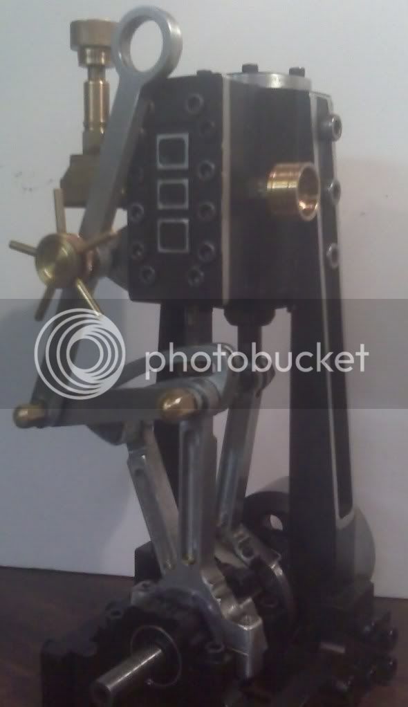
I am working on creating plans for this steam engine I designed. I am optimisticly calling it "Kelly's #1"
I have created a few .jpg images and a text document and put it in a folder. However I cannot upload a folder, only one image (or part) at a time.
How can I get this to the downloads section. I would like to contribute.
here is what I got so far. I would like some feedback on the usablility of these images.
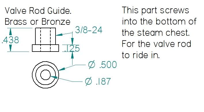
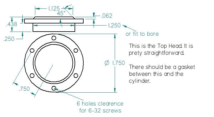
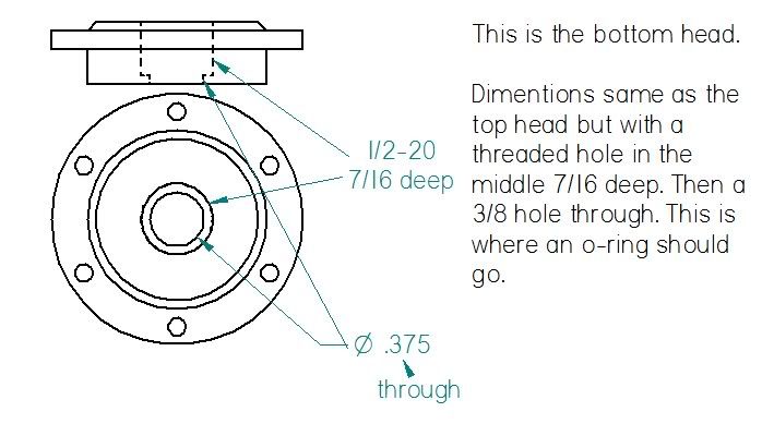
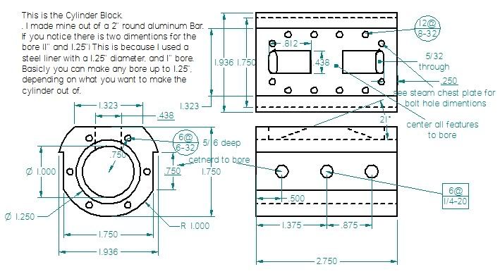
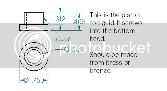
are these understandable?
thanks for viewing
Kel
I have created a few .jpg images and a text document and put it in a folder. However I cannot upload a folder, only one image (or part) at a time.
How can I get this to the downloads section. I would like to contribute.
here is what I got so far. I would like some feedback on the usablility of these images.
are these understandable?
thanks for viewing
Kel


