PatRoVa Rotary Valve engine

Home Model Engine Machinist Forum

Help Support Home Model Engine Machinist Forum:

This site may earn a commission from merchant affiliate links, including eBay, Amazon, and others.
Hello Nick Hulme

You wrote:

“Saying a flat surface is equivalent to an infinite spherical surface may be geometrically correct but it means nothing significant in your application, you're just using the old charlatan's trick of throwing irrelevant facts into the mix to obfuscate the BS by stating that you've "eliminated" something that isn't there.

I've made my living room floor comfortable to walk on in bare feet by eliminating all the sharp points in a flooring surface I haven't used and never had - there, easy!

Patents mean a lot, yes, but I stated thet patents do not mean that an invention is of any use and they do not prove the merit of anything, what percentage of patants granted have ever seen productive use, most of them are useless, verbose rubbish with lots of pretty drawings and little real substance, ringing any bells here?
The patent office will take the money of any unfortunate who comes along with a novel but worthless idea, sorry pal.

Air bearings are nothing new but by definition they are a clean technology - the complexity required to make this work with long term reliability in your rotary valve system renders your concept cost-innefective, and to manufacturers, very, very unnatractive, but I guess you've found that for yourself since your "Expo days"?

Just in case you are unaware and since you haven't mentioned it, to utilise air bearings in an engine environment you will need bump foils and complex surface coatings just to make it feasible for production use, and then you simply have to look at the one area where this is in development (and ask yourself why) - turbos, to see why design engineers aren't using or developing air bearings inside engines simply consider the fact that that (this is the "why" bit) the turbo is a small, light, easily replaced modular unit which is easy to swap out when it inevitably self-destructs and consumers are used to several turbo failures within the life of an engine.

I'm sure some technologies will come along which render you engine feasible for production but as it stands you've just re-hashed a load of old ideas and changed the shapes enough to get some patents but failed to change the technologies to a degree which results in a practical real world production engine.

You're a smart lad and you have a set of lovely curiosities but your incessant unproven insistance that they solve mankind's engine related woes coupled with overly verbose BS, huge swathes unnecessary illustrations
(I know you bought the software and think it's cute, it wears thin, believe me! You'd have been better spending the money on tooling so your in-house efforts looked more like the CNC work you farm out instead of something from J.C. Carpenters inc. of Nazareth) and your failure to sell so much as a toothbrush make you look so much like all previous Snake Oil salesmen and charlatans that it's difficult to resist a game of "Poke the Looney with a Stick"

I'm sure your ideas will make nice models, toys and perhaps lawnmowers but they are not the answers you keep insisting that they are, they're nice and you are a funny guy, but you need to be quick, have you looked at the market out there? Most of the new lawnmowers coming out are ELECTRIC ;-)”


It costs nothing to be polite.

When you rewrite your post politely, I will answer.

Thank you
[FONT=&quot]Manolis Pattakos[/FONT]
 
The simply genius aspect of a poppet valve is, that it does not move on the sealing surface when exposed to the maximum pressure of hot combustion gas. It stands still.
The second genius aspect is, that the hot exhaust gasses do not pass an oil film at any time with high velocity. In fact, the valveguide is protect by a small *pillow* of air next to the stem when the valve opens.
The requirements are met by constructional elements strictly separated, even by time. This is the best you can get in terms of engineering. Each functional surface/element has only one function independent from each other.
Plus it's simple and cheap to manufacture, the seal is somewhat selfadjusting in operation AND has proven useful in billions of daily use application.


Your valve lacks all of this.
There is relative movement of the sealing surface when exposed to hot exhaust gas. It is even worse: In the moment your valve opens to exhaust, hot gasses rage through the tiny orifice, heating adjacent material like a blowtorch in a spot that needs plenty of oil for lubrication constantly.
There IS a gap between your valve and the cylinder head. This ruins all alternative valve designs on the emission side.
The channels in the valve shaft call for casting as manufacturing process. The sealing surfaces must be hardened and ground, etc... it is rather complex in terms of cost, not small and cheap to manucfature.
I guess there will be serious distortion and deflection, too, when one side is heated by exhaust gas and the other one is cooled by fresh gas constantly. The sealing surface on the disk calls for absolute precision, see the gap problem some lines above.


Now to the constructive part of my post. You can test your valve just the way Felix Wankel did, using a sidevalve engine.


You might want to have a look at the ballvalve (German: Kugelventil) by Reinholt Ficht. Understand that it's rather advanced in terms of developent progress, understand it's limitations and you will easily understand the problems occuring with your own design.
 
Hello Till.

You write:
“The simply genius aspect of a poppet valve is, that it does not move on the sealing surface when exposed to the maximum pressure of hot combustion gas. It stands still.”


One of the characteristics of the PatRoVa rotary valve is that the total force acting on it, is permanently zero, no matter what is the pressure into the combustion chamber.

The bearings of the PatRoVa rotary valve run unloaded.

PatRoVa_comp.gif


PatRoVa_photo9.jpg


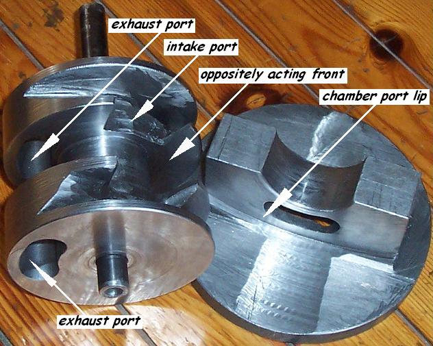
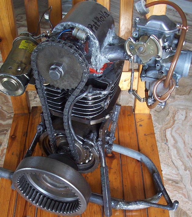
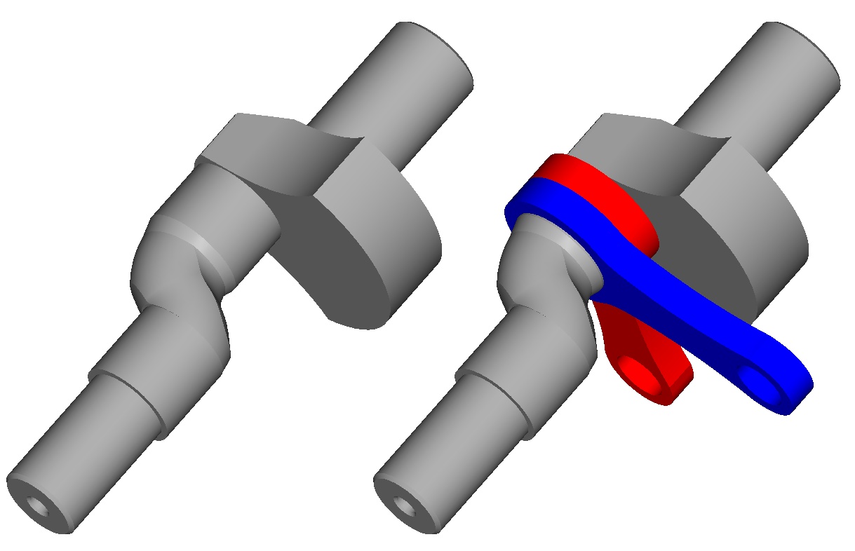
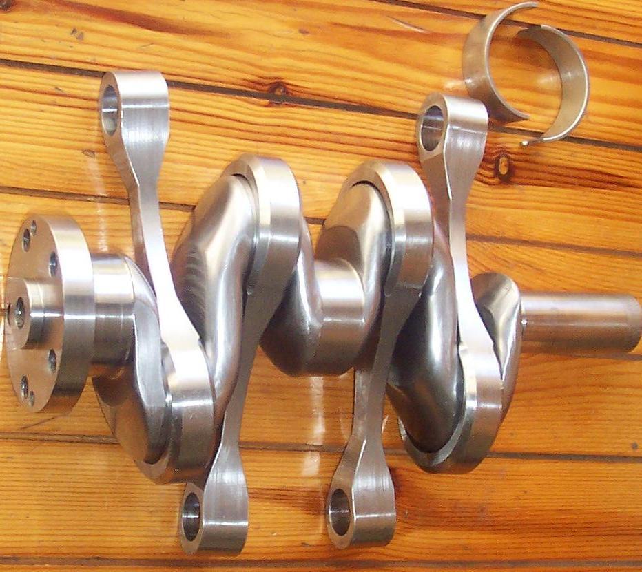
Spot on the size of the bearings in the drawing, spot also on the slim “shaft” (black, 13mm diameter) of the PatRoVa rotary valve of the prototype in the photo.

Without a force between the cooperating flat surfaces wherein the sealing occurs, the motion of the rotary valve during the high pressure period is not only harmless but advantageous (smooth running at constant angular velocity, vibration free, load free).

Do try to understand (to get) this big difference among the known rotary valves and the PatRoVa rotary valve: the same zero total force all around the 720 crank degrees.


In comparison, the “non motion” of the poppet valve at the high pressure period is followed by a period of “fast motion” wherein the valve requires strong forces to act on it in order to perform the motion it performs, which in turn results in unsmooth running (in a single or twin at low rpm idling, the flywheel has to be adequately large to store the required energy for the compression of the valve springs), in vibrations, in heavy loads in the valve train, in friction, in wear, in reciprocation of energy between the valve and the rest valve train, etc, etc.

Not so ideal as you described it.

A high revving engine requires big poppet valves, high valve lift (which means attenuated combustion chamber and low thermal efficiency) and stiff restoring valve springs.
If the revs exceed the rev limit (set, in most cases, by the valve train), a collision between the piston crown and the poppet valve is possible.
If the spring is not adequately stiff, and the acceleration / deceleration / jerk are beyond some limits, the poppet valve rebounds on its seat (or the cam lobe loses the control over the valve) destroying the breathing and causing wear of the parts.

Besides its high temperature (and the problems it causes) the exhaust poppet valve has another significant problem: it is he pressure into the combustion chamber just before the exhaust valve opening. Take the Ducati Panigale 1299. Its exhaust valve is 38.4mm in diameter, which means 11.5cm2. With 5 bars into the combustion chamber the time the exhaust valve is to open, the required force is increased by 11.5*5=57.5Kp (125lb).

Compare with the PatRoVa rotary valve wherein there is neither accelerations, nor jerk, nor resisting pressure.


You also write:
“The second genius aspect is, that the hot exhaust gasses do not pass an oil film at any time with high velocity. In fact, the valveguide is protect by a small *pillow* of air next to the stem when the valve opens.”

What do you mean by “oil film” in our case.

The problem of the exhaust valve is not the valve guide. The problem is on the valve head.

Consider the case the exhaust valve is open for, say, 1mm (the pressure into the combustion chamber is still high, and the temperature is extreme).
The exhaust gas cannot help passing with supersonic velocity by the narrow gap between the valve head and the valve seat.
I can’t imagine worst conditions for a part to live in.
Red hot gas is bellow the exhaust valve head, red hot gas is passing at extreme speed over the exhaust valve head (in the gap between the valve and the valve seat which is also heated).

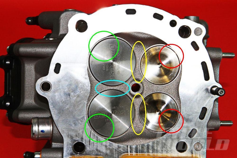
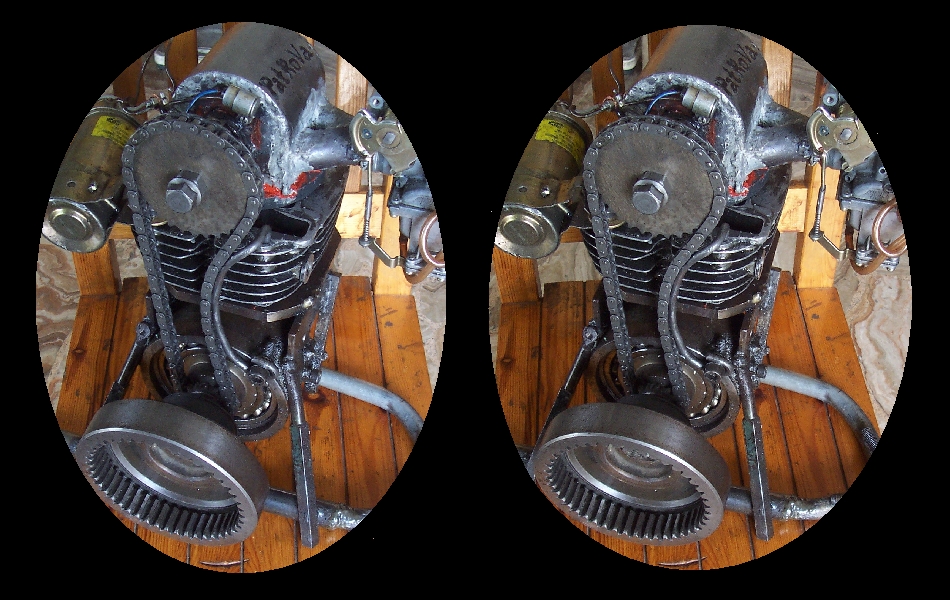
All the cooling in the cylinder head is concentrated around the exhaust valves. Spot on the cooling liquid holes (all but one are at the right side of the cylinder head) :

Ducati_Panigale_flow_restrictions.jpg


I wrote it in previous posts, but it is worth to be mentioned again: the thermal expansion in the cylinder head cannot help deforming the exhaust valve seats from circular (when cold) to oval (at one side of the big diameter exhaust valve seat the head is cold (yellow ellipse), at the other side the head is hot).


You also write:
“Your valve lacks all of this.
There is relative movement of the sealing surface when exposed to hot exhaust gas. It is even worse: In the moment your valve opens to exhaust, hot gasses rage through the tiny orifice, heating adjacent material like a blowtorch in a spot that needs plenty of oil for lubrication constantly.”

I explained in the previous paragraph how difficult are the conditions for the “head” of the exhaust poppet valve.

The conditions during the opening of the exhaust port of the PatRoVa rotary valve are quite similar with the conditions during the opening of the exhaust port of the Bishop-Cross rotary valve (backed by Ilmor and Mercedes).
No problem ever mentioned.
In a couple of years they achieved 10% more power than the best Formula1 engines (those with the “genius” poppet valves with the more than a century development); then the rules changed to ban the rotary valves from Formula1!

You phrase “hot gasses rage through the tiny orifice, heating adjacent material like a blowtorch in a spot that needs plenty of oil for lubrication constantly” fit perfectly with what happens in the poppet exhaust valves. Rethink about it.

As for the “plenty of oil” you are talking about, please explain what do you mean? Which oil? From where? For what?
The PatRoVa for normal; size engines (cars, motorcycles, aeroplanes, boats, trucks etc) is to run with dry cylinder head.
And this way it avoids several problems of the “genius” poppet valve cylinder heads such as the oil contamination by the exhaust gas, the oil suctioned through the valve guides, the degradation of the lubricant etc.


You also write:
“There IS a gap between your valve and the cylinder head. This ruins all alternative valve designs on the emission side.”

No.
As explained the PatRoVa rotary valve has an automatic built-in recycling of the leaked gas (it returns in the cylinder and is burned at the next combustion).

The real question is how much this leakage is.

If it is less, or comparable, to the conventional leakage from the combustion chamber to the crankcase (gas bypass through the gap between the piston and the cylinder liner), then what are we talking about?

If it is more, then it is not a matter of emissions (because it automatically recycles the leaked gas), but it is a matter of power loss.

Read my previous posts wherein the leakage of the PatRoVa is compared with the leakage in the Wankel model engine (the Wankel without side sealing means).


You also write:
”The channels in the valve shaft call for casting as manufacturing process. The sealing surfaces must be hardened and ground, etc... it is rather complex in terms of cost, not small and cheap to manucfature.”

No.
By far no.

The estimation for the cost of a PatRoVa rotary valve in mass production (including material, hardening, DLC coating, grinding, ect, etc) is: more than ten times lower than the cost of a Ducati Panigale cylinder head, with the PatRoVa being substantially more lightweight and compact and with substantially higher flow capacity and without rev limit and with by far more compact combustion chamber (try to rotate the camshafts of the Panigale at 7,500rpm (15,000rpm of the crankshaft) to see what I mean by no-rev-limit of the PatRoVa cylinder head).

Why the comparison is with the Panigale?

Because it is the only engine that can move reliably such big poppet valves, at such big valve lifts, at such high revs.


You also write:
”I guess there will be serious distortion and deflection, too, when one side is heated by exhaust gas and the other one is cooled by fresh gas constantly. The sealing surface on the disk calls for absolute precision, see the gap problem some lines above.”

You are wrong.

At the side of the ports of the PatRoVa rotary valve the tight sealing is useless. What do you need the tight fit when the exhaust valve is open, or at overlap, or when the intake port is open.

The sealing matters only at the opposite side of the ports, as the following animation shows:

PatRoVa_sealing.gif


and here in slow motion:

PatRoVa_sealing_slow.gif
.

The red colour of the window shows where high quality of sealing is required.
At that area the temperature of the PatRoVa rotary valve is substantially uniform (it is away from the ports).

Compare how much better are the conditions for sealing as compared to the Wankel model engine mentioned in the previous posts.

Compare how much better the two disks are secured to each other (relative to the interconnection of the flat covers of the model Wankel engine).

Compare what kind of materials can be used in the PatRoVa.

And let me know.


You also write:
“You might want to have a look at the ballvalve (German: Kugelventil) by Reinholt Ficht. Understand that it's rather advanced in terms of developent progress, understand it's limitations and you will easily understand the problems occuring with your own design.”

I saw the patent of Reinholt Ficht in the USPTO ( US4782801 )

It is like all the other rotary valves of the art (and similar to Cross and to Bishop design, with spherical shape in the middle so that a circular sealing can be used).

Like all the rotary valves of the prior art it undergoes the full pressure of the combustion chamber and its bearings have a difficult life.
Without a sealing mean, it is not functional because it cannot have and maintain the required tiny clearances.

Do you understand its difference from the PatRoVa rotary valve wherein the bearings are completely unloaded all around the 720 crank degrees?

Quote from http://www.pattakon.com/pattakonPatRoVa.htm :

“From a practical viewpoint:
Leaving free (i.e. without support bearings) the PatRoVa rotary valve on the cylinder head to seat in place and seal, by its oppositely arranged fronts, the two side chamber-ports, and applying a high pressure (like 100bar) in the combustion chamber, the PatRoVa rotary valve has no tendency to move upwards, or downwards, or to the side.
In comparison, a force of a few tons is required to keep in place a state-of-the-art rotary valve when the same 100bar pressure is in the combustion chamber; the extreme upwards force loads its bearings and causes, among others, the flexing / deformation of the spherical valve, of the shaft of the rotary valve and of the cylinder head wherein the shaft is supported.

The cavity of the PatRoVa architecture eliminates the radial forces acting on the rotary valve and on its bearings, which is a major (if not the worst) problem of the known rotary valve designs.

The ceiling of the PatRoVa cavity receives the heavy radial forces and releases, this way, the rotary valve from them.

The PatRoVa cavity is a buckler that protects the rotary valve from the radial forces.”


Thanks
[FONT=&quot]Manolis Pattakos[/FONT]
 
The bearings of the PatRoVa rotary valve run unloaded.

You keep making this point - zero load on the bearings. They will still require lubrication (obviously) but if they run unloaded at any reasonable rpm they will skid rather than roll, caused by the frictional force of the lubricant. Skidding bearings quickly disintegrate.

Don't think that lubricant creates drag? Think about when you're driving your car and one of the front wheels hits a deep puddle of water - the drag of moving the water out of the way tries to rip the car off the road in that direction. Now consider hitting a much more viscous fluid such as a deep puddle of oil, then the drag force will increase. In critical operations in industry, over lubricated bearings are almost as much of a problem as under lubricated.

So I can only conclude that you're wrong about the bearings seeing zero load (which you keep going on and on about), or your bearing life will be measured in minutes and hours rather than years.
 
Hello Cogsy

You write:
“You keep making this point - zero load on the bearings. They will still require lubrication (obviously) but if they run unloaded at any reasonable rpm they will skid rather than roll, caused by the frictional force of the lubricant. Skidding bearings quickly disintegrate.”


Don't forget the size of the roller bearings and the weight of the Patrova rotary valve and of the spline shaft that prevent the skidding you are affraid of

I keep making this point because if you understand how important it is, you will get the idea behind the PatRoVa rotary valve.

The ball roller bearings used in the prototype are sealed at both sides, so they keep their lubricant inside for their life-time and the cylinder had can remain “dry” (if desired, ceramic ball bearings can be used, but this is not necessary.

While these bearings are not loaded by the high pressure acting on the two disks of the rotary valve, they are slightly loaded by the timing belt or chain that drives the rotary valve (it is easy, but not necessary, to remove this load, too).


And why the zero total force (and so the unloaded roller bearings) are important?

Take the Bishop rotary valve:

Bishop_Rotary_Valve.jpg


and think what is happening during the high pressure portion of the cycle (i.e. during the last part of the compression, during the combustion and during a part of the expansion).

Through the rectangle window the high pressure gas pushes upwards the rotary valve (a rough calculation: with 20cm2 window area and 100 bar peak pressure, at the time wherein the valve is pushed upwards by 2 tons, at the same time it needs its best sealing, i.e. the minimum clearances).

The Bishop rotary valve (which is a large diameter tube with slim walls and long ports on its periphery) is rotatably mounted on the cylinder head by two big diameter (big diameter: because the fresh charge and the exhaust gas pass though these bearings) needle roller bearings, which are mounted at the sides of the cylinder, i.e. at a long distance from each other.

Due to the heavy force pushing “upwards” the valve, the valve bends / deforms (it is supported at its two ends only) increasing the clearance between its lower side and the window though which it communicates with the combustion chamber.

It is also the required clearance of the big diameter needle roller bearings: this clearance is added to the rest clearances.

It is also the distortion of the cylinder head whereon the needle roller bearings abut on, which further increases the clearances.

Worth to mention: the needle roller bearing at the exhaust side of the Bishop rotary valve runs too hot (all the exhaust gas passes through it).

Is it possible, without sealing means, to have and maintain the required tiny clearance around the “window” during the high pressure portion of the cycle?

Practice says: No.

Additional sealing means means friction, wear, complication, cost, reliability issues, need for lubricant (which ends up into the combustion chamber spoiling the combustion and the emissions), etc, etc


And don’t think the Aspin rotary valve is better..

Quote from http://ralphwatson.scienceontheweb.net/rotary.html :

“I first became interested in the rotary valve as applied to internal combustion engines around about 1939, after reading an article in a motor cycle magazine describing an Aspin rotary valve four stroke engine. This engine had a capacity of 250 c.c. and it was claimed to produce 29 h.p. at 14,000 r.p.m., using low octane petrol.
At the time, I was living in Nelson and serving an engineering apprenticeship. On occasion I watched a group of engineers, led by the well-known aviator George Bolt, race one metre hydroplanes on the local model boat pond.
These model boats were powered by 30 c.c. engines and ran tethered to a central pole in the pond to provide quite exciting action. Being an enthusiastic experimenter, the Aspin engine came to my mind and I decided that I should give them some competition.
With great, but what turned out to be misguided enthusiasm, I built a model engine based on the Aspin design, which incorporated a cone type valve the same diameter as the cylinder bore, rotating in the cylinder head. The combustion chamber was contained within the rotary valve, which rotated to line up in turn with the spark plug, exhaust port and inlet port.
Full combustion pressure was applied to the valve, forcing it into the taper of its conical seat with the object of ensuring a good seal, but this arrangement could result in the valve seizing in the head due to lack of clearance and lubrication. In order to counter this, the Aspin design incorporated a roller thrust bearing on the valve stem.
I used the same arrangement but could not attain an adjustment whereby the bearing took the load and a satisfactory seal was achieved. When adjusted so that load was on the bearing, the seal leaked and the engine had poor compression and would not run. With load on the cone the valve would seize. After suffering much frustration with broken drive shafts and stripped gears, the engine was eventually run for short periods with load on the cone, thanks to a copious supply of castor oil. This was supplied under pressure to the valve face, by means of a hand pump. My goal of fitting the engine into a model hydroplane came to naught and George Bolt and company remained unopposed at the model pond.
However I was able to test the engine running against a brake and it recorded 1/8 h.p. at 8,000 r.p.m., which was a disappointment when related to the figures quoted in the article which had inspired my efforts.
Many years later the story came out that the Aspin engine was tested by the motorcycle manufacturers Velocette, who found that it produced only half the horsepower claimed, the suggestion being that the original testing had been carried out with a wrongly calibrated tachometer.”

End of Quote.


As Watson writes (and as practice proves) the tiny clearances and the heavy loads on a rotary valve were, so far, two incompatible requirements.

The PatRoVa rotary valve takes the heavy loads (and cancels them internally without loading its bearings) keeping the tiny clearances tiny.


If something is confusing, please let me know to further explain.

Thanks
[FONT=&quot]Manolis Pattakos

[/FONT]
 
Hello Kvom.

You write:
“I keep wondering what the point of this thread might be.”

I open this thread.

And the point was to show to the “Home Model Engine Machinists” a new different 4-stroke model engine design, with the hope that at least one Machinist to become interested to built a PatRoVa prototype model engine and to evaluate it as a third party.

This is why the CAD drawings were given: to be used as the basis for modifications.


Here is the first full size “low budget / proof of concept” PatRoVa prototype (75mm bore, 80mm stroke, cylinder and piston rings from an old Yamaha 250XT):

PatRoVa_photo8.jpg


And here at operation (youtube video):

[ame]https://www.youtube.com/watch?v=6Q-EGdeS0ws[/ame]


Some forum members blamed it for its poor manufacturing quality.

It is not just poor.
Its manufacturing quality is by far worse than poor.

Some US20$ were spent for the required materials for the cylinder head and the rotary valve (the rest parts – i.e. the “conventional” parts (even if they are not so much conventional) were available from an older project).


However,
if I were you,
I would wonder how on earth this prototype, made at such bad quality and at such low cost, does work.

And works well.

See carefully the flame and listen carefully to the sound: there is not even one misfire.

As for the leakage from the cylinder head of the PatRoVa, what I am sure for, is that it is less than the leakage from the worn cylinder / piston rings.


You also write:
“OTOH, Manoli's skills in 3D modeling make interesting viewing.”


To make the thread more interesting, several drawings were made not just in 3D, but in stereoscopic format (or ghost stereoscopic format).

It is a useful tool when you get it (ask IceFyre13th).

Several people think they are unable to look “stereoscopically”.
They are wrong.
If they have two eyes (both functional) and are capable to see things close to them and away from them, then they have everything it takes to see stereoscopically.


Give me just 2 minutes of your time and try to apply exactly the following simple instructions.

PatRoVa_Prot_Ster2.jpg


Put the above pair of photos of the PatRoVa prototype at the middle of the screen.

There are two flywheels. Do you see them at the bottom of the photo? (the big diameter ring gears).

Keep your head so that the line connecting your eyes to be parallel to the line connecting the centers of the left and right flywheels (or simply keep your head straight and the screen horizontal).

Keep the bottom of a pencil by your hand and displace it so that its nose to get at the intersection of the line from your left eye to the right flywheel center and the line from your right eye to the left flywheel center..

Focus your sight at the top end of the pencil.

At the background they appear (not very clear, but they appear) three images.
Slightly move your sight higher than the pencil nose and focus progressively on the central “stereoscopic” image ignoring the side images.


And let me know.

Thanks
[FONT=&quot]Manolis Pattakos

[/FONT]
 
Censored


....................................
 
Last edited:
I would like to thank the "Elite" members here who have now ruined this post for me...............your a bunch of bullying keyboard warriors who have nothing better to do than be rude and inconsiderate of others.

To quote the most obnoxious one "Silence is Golden, especially when "The Nutter on the Bus" finally gives his mouth a rest"

How about you take your own quote and effectively do what it says.....or instead of being a "know it all" add something to the conversation constructively.
 
Given that this is a HOME MODEL site, and that very few of the models we build are particularly efficient, I think that badgering Mr. Pattakos about his design is inappropriate. If someone wants to build it, they can have at it from the plans.

Let's have no more of this rudeness please.
 
I will thank mr Manolis for sharing his visions and have at no time felt lured to invest a fortune.
It is to me far more interresting than Olympic games or Brexit.
 
Hello Niels Abildgaard.

I hope you will like this post.

The idea was to design / make a V-2 at 90 degrees (pretty good balancing, low inertia torque, easier cooling, shorter and stronger crankshaft etc).


In the initial design (previous posts) the crankshaft extends (as in most, if not all, model engines) at the one only side of the crankpin. While it is simpler and easier to make, it may prove problematic at higher revs.
A crankshaft supported at both sides of the crankpin is stronger and preferable, but it requires divided connecting rods.


In this drawing:

PatRoVa_model_V2_Make_crankshaft.jpg


the crankshaft is supported at both sides of the crankpin.
The main crankshaft journals are 12mm in diameter while the crankpin is 13mm in diameter. Is it obvious how the single piece connecting rods are assembled?

In the following drawing:

PatRoVa_model_V2_Make_1.gif


at right you can see the crankshaft with the “secondary” balance web assembled on it. The big balance web is integrated on the crankshaft. The two balance webs together offer the vibration-free quality of the best V-2 engines (like the Ducati Panigale).

The casing is a single piece and comprises the crankcase, the two cylinders and the “lower half of the cylinder head” of each cylinder. No studs or bolts are required.

Spot on the openings at the sides of the crankcase, and think how much the crankshaft can “play” (be displaced) into the crankcase before the installation of the ball roller bearings (which are to be, initially, the conventional “6201” 12x32x10, and later spindle ball roller bearings (same dimensions) capable for more than 50,000rpm).

The freedom of the crankshaft in the crankcase allows the assembly of the single-piece connecting rods and of the pistons. Think of it.


In the following drawing:

PatRoVa_model_V2_Make_2.gif


the ball roller bearings are assembled and keep the crankshaft in place.


In the following drawing the rest parts (rotary valves, cylinder head covers (blue), sprockets, timing belt etc) are assembled.

PatRoVa_model_V2_Make_3.gif


The power is provided by the strong side of the crankshaft (the side wherein the big balance web is (it is the front side in the drawing)).
The timing sprocket are at the other side of the crankshaft.


The difficult part is the casing.


The following drawings show the steps required for the manufacturing of the casing:

PatRoVa_model_V2_Make_block_stages_1.gif


PatRoVa_model_V2_Make_block_stages_2.gif


PatRoVa_model_V2_Make_block_stages_3.gif


The first steps are the most significant: boring of the two cylinders, boring of the nests for the roller bearings of the crankshaft. The axes of these three cylindrical cuts must precisely be orthogonal (perpendicular) to each other.

I think the drawings talk by themselves.

If there is something confusing, just let me know to further explain.


With 13mm stroke and 24.8mm bore the V-2 model engine has a total capacity of 12.5cc. Its bore to stroke ratio is the same with Ducati Panigale 1299 (116mm bore, 60.8mm stroke.

The initial metal plate from were the block was made is 50mm x 90mm x 90mm


The architecture looks good not only for model engines, but also for normal size engines (say a V-2 1300cc).

In case the plain bearings are preferable than the roller bearings (say, as happens with the Ducati Panigale), the ball bearings can be replaced by aluminum rings having the plain bearings at their centers.


Thanks
[FONT=&quot]Manolis Pattakos
.
[/FONT]
 
Hello Niels.

Ducati insists on the “conventional” single-piece “heavy” crankshaft.

The photos are from the CycleWorld:

Ducati-1299-Panigale-08-590x520.jpg


At right is the Panigalle 1299 crankshaft (focus on the balance webs).

Ducati-1299-Panigale-09-590x393.jpg


Ducati-1299-Panigale-10-590x393.jpg


Even in their Superleggera Panigale 1199 (which is their top model at some US70,000$) wherein every removed gram of weight is, literally speaking, “gold”, and wherein the rev limit is at 12,500rpm (25.33m/sec mean piston speed), the crankshaft is conventional.


Worth to mention:
The force (either due to the pressure in the combustion chamber, or due to the inertia) on the crankshaft of a V2 maximizes when the piston is close to its Top Dead Center. This force is about equally shared between the left side and the right side of the crankshaft (left and right relative to the crankpin).
But as regards the torque, only the one side of the crankshaft really works.


No doubt, the Hirth maneton couplings is a more elegant way.

And it allows single piece connecting rods in multicylinder engines.

However, in terms of strength and of high revving capability, it is not comparable to the conventional single piece crankshafts.

As for the manufacturing of a Hirth maneton crankshaft, it appears far more difficult than manufacturing the complete PatRoVa engine (the crankshaft included).


The crankshaft of the last version of the V-2 PatRoVa combines the advantages of both schools: the strength and the simplicity of the conventional single-piece crankshaft with the single piece connecting rods.


By the way,
here is the single-piece crankshaft and the four single-piece connecting rods of the PatOP Opposed Piston prototype Diesel engine:

PatOPpro6.jpg


And here is the same engine operating on Diesel fuel (compression ignition), standing free on a desk:

[ame]https://www.youtube.com/watch?v=2ByEgfTTq1I[/ame]

For more about the PatOP: http://www.pattakon.com/pattakonPatOP.htm )


Thanks
[FONT=&quot]Manolis Pattakos
.

[/FONT]
 

Latest posts

Back
Top