Over center manual cone clutch

Home Model Engine Machinist Forum

Help Support Home Model Engine Machinist Forum:

This site may earn a commission from merchant affiliate links, including eBay, Amazon, and others.

Brian Rupnow

Design Engineer
Project of the Month Winner
Joined
May 23, 2008
Messages
14,886
Reaction score
8,213
Location
Barrie, Ontario, Canada
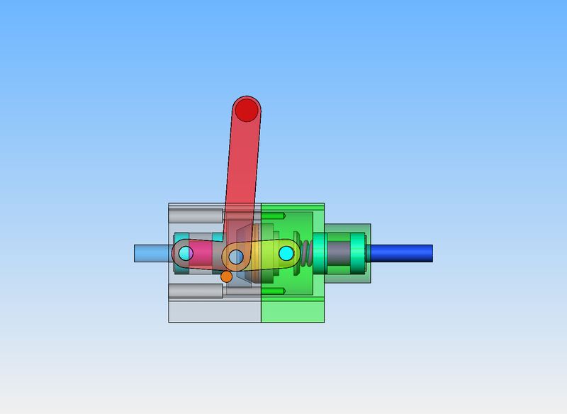
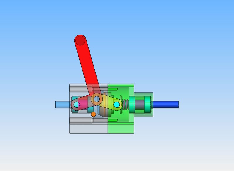
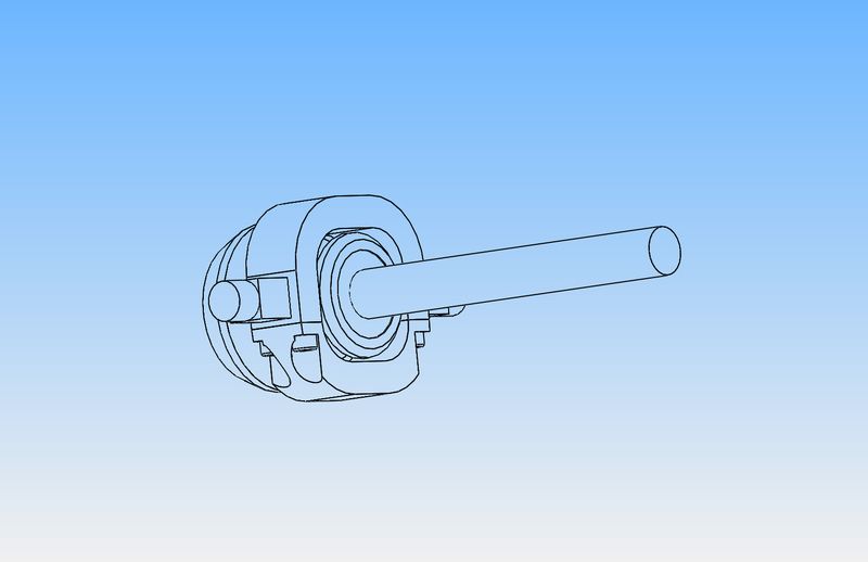
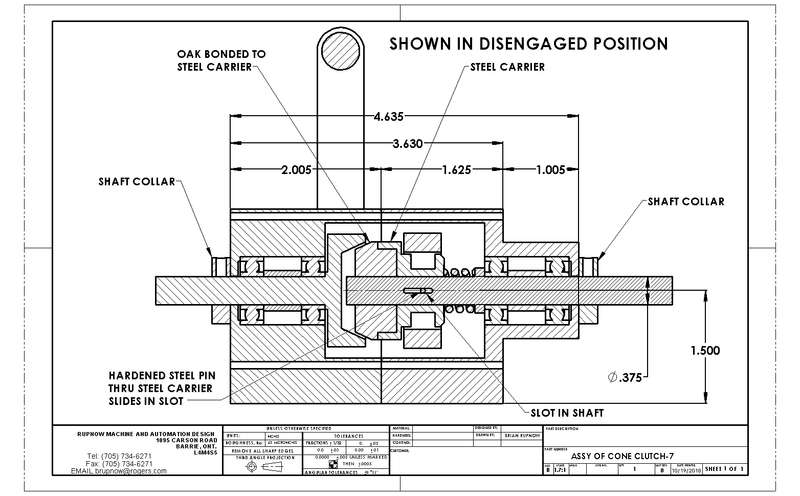
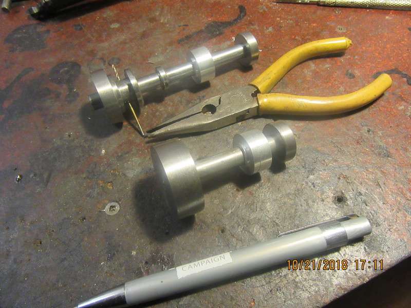
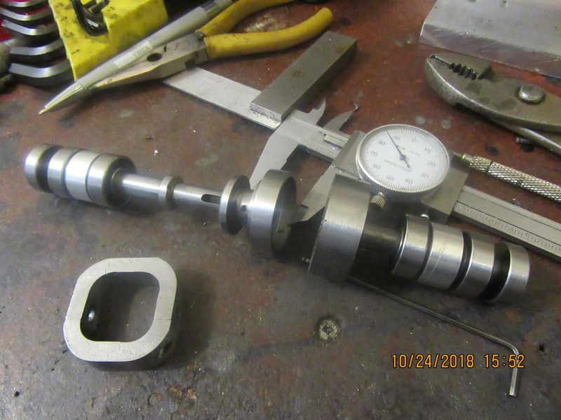
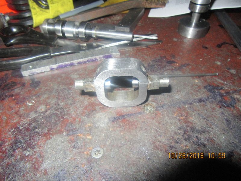
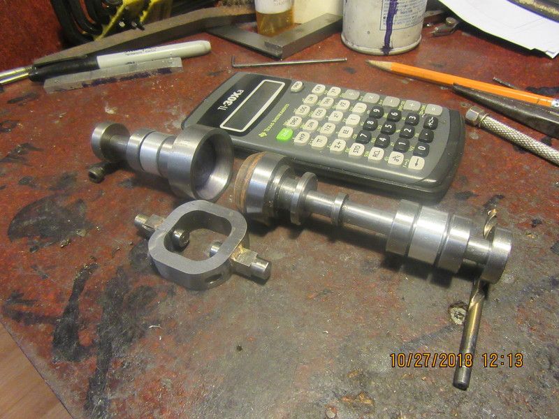
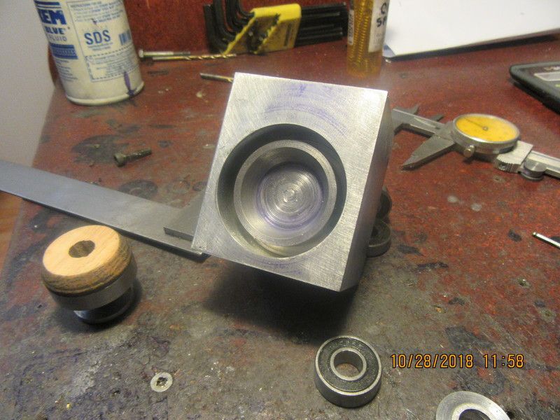
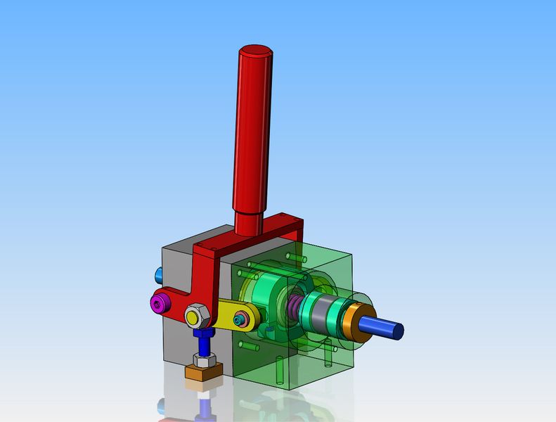
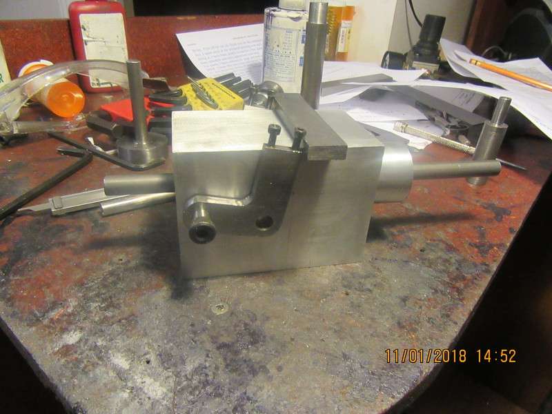
I seem to have clutches on the brain this last couple of months. This design incorporates a cone seating into a cone shaped recess to transmit torque from the left hand shaft to the right hand shaft. There is a very powerful coil spring that holds the clutch in the engaged position. When the handle is swung to the left it allows the powerful spring to seat the cone firmly into the cup and transmit torque. When the handle is swung to the right it separates the cone and cup and compresses the spring. The fact that the spring will be compressed by this action will make the linkage lock into an "over center" condition and stay there until it is changed by someone manually swinging the red handle.
Yt0ALf.jpg

8NkX4t.jpg
 
The design is easy.--The finessing not quite so much. I lay in bed last night thinking of how these parts would fit together, and realized that if that center hoop was built as a single part I would never be able to fit it into place around the carrier that holds the oak friction disc.--So--we make the carrier a two piece so it can be assembled.
xrmc07.jpg
 
I didn't have a lot of time today for this project, but it has moved ahead a little bit. Collars have been added to the shafts to keep them from moving axially, and the right hand outer housing had to get 1/4" longer, as I was running out of room.
pWPBYH.jpg
 
I managed a little shop time this morning. Machined the steel carrier for the oak cone and the shaft it rides on.
b98nvW.jpg
 
I made the shaft and cup that the cone fits into. To save myself a ton of machining I made it from two pieces, then Loctited and pressed the two pieces together. Tomorrow when the Loctite is well set up I will drill a 1/16" hole thru both and Loctite in a piece of 1/16" drill rod. I will machine the cone into the face of that solid piece tomorrow.
gZp7PF.jpg
 
Not a real lot done today. The two external shaft collars and the two bearing spacers. The two bearing spacers got a lot fatter, because if I left them as thin wall, sooner or later I would want to pull a shaft out of the assembly, and when you do that the spacer falls down between the two bearings and it's a devil of a job getting them lined up again to get the shaft back in. The tunnel they fit into is 0.906" diameter, the outside diameter of the spacer is 0.875" diameter. I spent this morning going with youngest grandson Jake (3 year old) and his mom and goodwife out to a local farm that sells pumpkins. Of course you have to pay the $12 per person to get in, which entitles you to a wagon ride out to the pumpkin patch and one pumpkin. Lots of plastic ghosts and skeletons and scary witches along the trail the wagon takes to get out to the patch. Jake was very pleased with the entire event but wife and I damned near froze to death!!! I had to come home and have a snooze to recover, then headed down to the shop to make at least a couple of parts.
WNfRJY.jpg
 
Just my 2 cents worth but those little 3x8mm bearings are going to be under a lot of load.
A better idea would be at least a large ball bearing fitted on the shaft with a traversing yoke around that operated by the lever.
 
Or you you could change the inner bearing to a 7200 sealed angular contact which will take a higher load
 
I have just realised I gave a metric bearing number . I don't speak inches
 
No great strides made on this project today, but my bearings came in from Canadian Bearings. I have spent the entire day running around like a chicken with no head, trying to source replacement gears for my three ball governor. Someone purchased the plans but the gears I have in the plans call for an 8 tooth pinion, and nobody makes a bevel gear in that size anymore.
orFOTa.jpg
 
Things have been a little crazy around here for a few days, however progress is being made. The center bearing carrier is made and the two small bearings have been Loctited onto the stub shafts, which are silver soldered to the outer frame. The outer frame is two piece, and the tapped holes for the bolts which hold the two pieces together are tapped thru the stub shafts after brazing.
59esmM.jpg
 
All of the inner workings of the clutch are finished. The next step will be to make the outer housing of the clutch. I do have a spring, but it has to be shortened a bit.
4A8SGv.jpg
 
Its been a very boring morning (cough-gag--bad pun). The boring went fine in the four jaw chuck of the lathe. I really don't like working inside something like that where I can't see whats happening. It just requires a lot of faith in the dials and digital read-outs. I have to buy a piece of aluminum big enough to make the other housing from.
yB0PgH.jpg
 
As I work my way into this clutch business, I have to keep updating the solid models to reflect what I am actually building. This involves adding shoulder bolts at the pivots, and socket head capscrews and flatwashers, and a mechanism to dial in just how far "over center" I want the handle to move before locking up. I had to go to Toronto on business today, and then had a bit of real work, so nothing actually happened except updating the solid model.---Brian
x9nABy.jpg
 
Hi Brian. Very interesting project. For small gears (at a reasonable price) I’ve had good results with Hobby Wholesale (https://hobbywholesale.com/) there in Canada so no hassles with exchange rates and waiting for orders to clear customs. They also have the module pitch in a lot of there descriptions.
 
Thanks bmac2--I do have a complete set of gear cutters, 24 dp, so I cut all of my own spur gears. I may require some other types of gears though, so I will have a look at the link you posted.---Brian
 
Things are not happening at a blazing pace, but they are happening. The second half of the main body is completed, and all of the bearings and spacers are loctited into place with a solid alignment rod thru everything until the Loctite sets up. Two of the external links are made and shown in place. All of the inside components are finished and waiting to be assembled. I have been sick with the sore throat from Hell, but will probably live thru it.---Brian
xJDGbZ.jpg
 
Back
Top