Nitro V8

Home Model Engine Machinist Forum

Help Support Home Model Engine Machinist Forum:

This site may earn a commission from merchant affiliate links, including eBay, Amazon, and others.
Regarding your question about Glow plugs, the length of thread on a OS #8 plug is 4.5mm (0.177") and the thread is 1/4x32 UNEF.

Looking at your piston drawings do you think rings are really needed? Steel liners and CI pistons are quite common on Glow and diesel engines. I've just finished a glow motor with the plain CI piston lapped to the liner and thats good for 10,000rpm with a 10x6 prop

http://youtu.be/AvbnjyrHq8M

J
or make use of the scorpion v8 plans that are already done sic issues.
 
its a small collage. our edm is cobbled together just big enough for tap removal it would take a day per hole. the broach i have works basically works by pushing a tapered square file through a pre drilled hole hopefully this wont distort the web to much

as for a one piece crank i didn't leave enough room for two piece connecting rods.

I would definitely consider the crank design shown in that link rather than your press fit crank. Although you may need to seal each pair of opposing cylinders from the rest to maintain some sort of crankcase pressure to aid in supplying each pair of cylinders with fuel.

The difficulty with your design will come when you try to press the pieces together. If you don't have perfect alignment in all planes at the time they are pressed together, it's game over, your crank will come out twisted in one way or another and attempting to correct it will most likely result in a weak joint. Not something you want in a crankshaft.

I noted that you said you didn't leave room for 2-56 SHCS, have you got room for 0-80 SHCS which are a bit smaller than the 2-56's? You could also go smaller, 00-90 for example, if you don't mind using jewellers screwdrivers to tighten them up ;)

Also, why the rotary valves? why not just use cylinder porting like most commercial two stroke aero engines? It'd be a lot less complicated and easier to make?

Sorry, don't mean to sound negative, just a few questions I have is all. I do like the concept though :)

When using valves as in a four stroke you use one intake valve diameter as a guide for the carburettor opening. The venturi would be slightly smaller.

I have no idea how to apply that rule of thumb to a two stroke though ... :D
 
The difficulty with your design will come when you try to press the pieces together. If you don't have perfect alignment in all planes at the time they are pressed together, it's game over, your crank will come out twisted in one way or another and attempting to correct it will most likely result in a weak joint. Not something you want in a crankshaft.

I noted that you said you didn't leave room for 2-56 SHCS, have you got room for 0-80 SHCS which are a bit smaller than the 2-56's? You could also go smaller, 00-90 for example, if you don't mind using jewellers screwdrivers to tighten them up ;)


Sorry, don't mean to sound negative, just a few questions I have is all. I do like the concept though :)

:D

Yes I was thinking along the same lines and unless you put a small radius on the corners of the square spigots at either end of the crankpins and the square holes in the Webs as is standard practice with aerospace components. you will get stress raisers at the corners. which could lead to fatigue cracks. especially in a small high revving engine like this.

I'm not saying it can't be done and the theory is sound given the caveat above but it would probably need a precise jig to be made to ensure all the press fits are spot on. If you were mass producing them this would be the way to go but for a one off you would probably spend much more time designing and making the jig than the actual crankshaft.

Regards Mark
 
Skyline1
C.I. bearing do they work at low speed (idle) with no forced oil.

trumpy81
I don't need to seal the different cylinders because I'm using a supercharger. That is also why I'm using the rotary valve, so i can build boost. also i cant use the bearing crank cause it would get into my cylinder walls and crash my pistons.

as for the crank, for rotational alignment, as long as all the webs and drill rods are the same it should all line up.(i would think at least with 90 degree offsets to me throws) for sticking a square block in a square hole I had thought it would self align.

If I made the main bearings and webs one piece and added the throw would something like that work better? I'll also do some modeling to see if 0-80 screws might work for rod caps.
 
ok then I increased my deck height and increased my con rod length. as long as you think 0-80 shcs will hold up i can use a solid crank. now to contemplate this new can-o-worms. since its going to be a softer metal what bearing material should i use?
 
Hi Michael

Yes C.I. bearings can be used at slow speeds I have used them on oscillating engines. (wobblers). like this one I estimate it's speed at about 400 to 500 R.P.M.

DSC_0069.jpg

DSC_0070.jpg

DSC_0072.jpg

Lubrication would be a bit of a problem but C.I. is at least partially self lubricating. This is due to the free graphite in the iron. You will soon know about this when you have to machine some (your hands will be black in no time). As I have never run them completely "Dry" I could not be sure but I doubt they will need force lubrication. How do you intend to lubricate the bottom end by the way

The crankpin in this one is (I think) Mild steel and it seems to run pretty smoothly. So plain mild steel may be a suitable material for your crankshaft if it is rigid enough You could still use Drill rod as it can be softened (Annealed) as well as hardened. It is a little pricey in larger sizes though.

When this engine approaches construction I can provide you with some Cast Iron Bar for making bearings for the cost of the postage. It shouldn't cost too much to ship a small piece to the States

These are by-products of my little foundry (casting sprues) and is the material I use myself it's soft grey iron and machines really easily. It can be made into really thin bushes and shells. The crankpin Dia. on the little oscillator is 1/8" so you can see how thin it can be turned.

Regards Mark
 
Skyline1
C.I. bearing do they work at low speed (idle) with no forced oil.

trumpy81
I don't need to seal the different cylinders because I'm using a supercharger. That is also why I'm using the rotary valve, so i can build boost. also i cant use the bearing crank cause it would get into my cylinder walls and crash my pistons.

as for the crank, for rotational alignment, as long as all the webs and drill rods are the same it should all line up.(i would think at least with 90 degree offsets to me throws) for sticking a square block in a square hole I had thought it would self align.

If I made the main bearings and webs one piece and added the throw would something like that work better? I'll also do some modeling to see if 0-80 screws might work for rod caps.

That makes more sense, for some reason I thought you were using the rotary valves for the exhausts .... doh!

In that case the supercharger plus rotary valve should work, but you'll need to isolate each cylinder from the other along the valve to prevent fuel from leaking into other cylinders at the wrong time. A plain lapped valve might work but under pressure, albeit small, from the supercharger it could easily force a small amount of fuel past any clearances you may have in the valve, not to mention reducing crankcase pressure which would have the opposite effect. a few O-rings should solve that problem but getting the grooves just right so that there is little drag but full sealing at full operating temperature will be tricky to say the least.

The 0-80 SHCS will work no problem at all. The only purpose of the rod cap is to stop the rod from flapping about, there is no real load on the cap itself.

There is another solution for the crank that I saw recently on Youtube. A Japanese gentleman used a bearing to hold two horizontally split sections of the crank together. It's more difficult to describe than it is to understand it when seen. I will try to find the video again although it may be difficult as the title was in Japanese :(

Visualise this, each crank section features 2 webs, one on each side, plus the offset rod. Then each end of this section has a shaft that is machined in half to form a D shaped shaft. There are four of these assemblies with each pair of D shaped shafts mating together inside the ID of the bearing. They are then held together with a small bolt through the center of the two shaft sections and the bearing.

The video shows it much better .... ;D;D;D

For big end bearings, you could use some .005" phosphor bronze shim stock. You'll need to make a couple of dies to form and punch/drill for the cap screws but that's all part of model engineering ;)
 
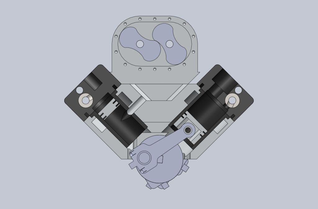
the rotary valve is for exhaust. air/fuel mix goes through the supercharger into the valley. the valley has ports leading to cylinder. as the piston moves down the cylinder the exhaust valve starts to open. at roughly .125in from bdc the exhaust valve is completely open and the intake port is starting to be uncovered. at bdc the exhaust valve is closed and the intake port is fully uncovered. so the burnt gasses are pushed out the cylinder.

I'm going to use a solid crank with C.I. bushings. i might make two different styles of crank. a 90 degree offset and a 180 degree offset crank. with a flat (180 degree offset) crank it would sound more like a 4 stroke V8. at least i would imagine it would. two cylinders would fire at the same time so there would be 4 pops per revolution like a 4 stoke. plus it might increase torque. lol

if i used a splash oil system would i need to worry about what oil i used. at tdc the intake ports are open to the crank case so fuel could get into the oil. i don't know if glow fuel will effect an oils lubricating ability.
 
Hi Michael

In many engines a small percentage of oil is mixed with fuel (or the energy transfer medium like steam) for lubrication. displacement lubricators in Steam engines, the petroil system in two strokes and small gas turbines use it as well. In some gas turbines (mini jets) it serves a dual purpose of cooling the bearings as well.

The Nitro fuel you are intending to use probably has a small percentage of oil in it. (Castor oil I believe but I may be wrong).

As to whether reversing the mix i.e. getting a small percentage of fuel in the oil would be detrimental I couldn't be sure. But provided the oil is changed fairly often I don't think it will be a problem but I'm not an expert on this.

The Model Jet guys use a 4% mixture in the fuel of either turbine oil (Shell 500 I believe) or 2 stroke racing oil (like Castrol R which is Castor oil based).

If, as you say, fuel is admitted to the crankcase during part of the cycle, it might be possible to lubricate the whole engine this way.

Just a few thoughts, the model jet forums might be able to give you some advice too.

Regards Mark
 
Glow or nitro fuel has 15-20% oil so if you are feeding the air/fuel mix via the crankcase then you won't need additional oil.

If your inlet ports are not open to the crankcase then you will need some means of oiling the lower end in which case the same castor or synthetic oil that is in your fuel would be best as any drawn into the cylinder will just burn off.
 
can anyone tell me the carb barrel port size on a .12ci/2cc nitro engine? given the effective displacement ~.137ci and the fact that i have two intake ports open at a time I think 2 carbs of roughly .12 size would be a good place to start for carb sizing. i got the effective displacement by multiplying one cylinders displacement .098ci by boosted pressure ratio (14.7+6)/14.7=1.4

I would also like your input on tolerancing the rotary valves. i was thinking .0015-.002. The valve is going to be hot and i don't want it seizing or to loose to much compression to blowby.
 
the rotary valve is for exhaust. air/fuel mix goes through the supercharger into the valley. the valley has ports leading to cylinder. as the piston moves down the cylinder the exhaust valve starts to open. at roughly .125in from bdc the exhaust valve is completely open and the intake port is starting to be uncovered. at bdc the exhaust valve is closed and the intake port is fully uncovered. so the burnt gasses are pushed out the cylinder.

I'm going to use a solid crank with C.I. bushings. i might make two different styles of crank. a 90 degree offset and a 180 degree offset crank. with a flat (180 degree offset) crank it would sound more like a 4 stroke V8. at least i would imagine it would. two cylinders would fire at the same time so there would be 4 pops per revolution like a 4 stoke. plus it might increase torque. lol

if i used a splash oil system would i need to worry about what oil i used. at tdc the intake ports are open to the crank case so fuel could get into the oil. i don't know if glow fuel will effect an oils lubricating ability.

So I was thinking on the right path to begin with re: rotary valve.

OK, with your crankcase pressurised there is a very real possibility that you will get fuel being forced into the cylinders past the piston, whether you have rings or not. You have to remember that you will need clearance between the piston and the cylinder wall. How much clearance depends on material choice but you will need clearance!

It would be better if the rotary valve controls the intake and use ports for the exhaust, that way you could control the fuel intake more effectively. Of course that will mean you need lubricate the bottom end with a few drops of oil before any running, but with the blow by past the piston, the fuel/oil mix will maintain the lubrication of the bottom end.

As for C.I. versus Bronze for plain bearings, it makes little difference provided the plain bearing has been designed correctly to begin with. A poorly designed plain bearing will gall the shaft and itself regardless of the material used.

You'll find some useful information about plain bearing design here:
http://wikihelp.autodesk.com/Invent...ineer1994/2105-Bearings2105/2122-Plain_Be2122

There is also a plain bearing calculator available somewhere on the net, I used it when designing my V8. Here's the address to one calculator, but it's not the one I used:
http://www.vesconite.com/design/bush/entry_alldesigns2.htm

You'll find the calculator that I used here:
http://www.metalstop.com/
 
re: rotary valves
no i cannot use the valve for intake. first having an exhaust port means that the port is open equal time on both the down and up stroke. I don't want this. I want the exhaust to open before the intake to relieve pressure. then open for a period of time with the intake to allow exhaust gasses to be forced out. then the intake to be open by itself to allow the cylinder to be brought up to boost pressure. My current configuration allows for this. It also helps keep the piston cool. This configuration is based of the two stroke Detroit diesel.

First off, the Detroit diesel injects fuel directly into the combustion chamber it does NOT pressurise the crankcase and then force fuel past the pistons into the combustion chamber.

Forcing fuel past the piston will alter the intake timing when compared to direct injection also.

To replicate the Detroit diesel, you will need to have the blower feed fuel/air directly into the combustion chamber. For that to work you would then need another rotary valve or a piston controlled port. That is why I suggested the intake be controlled by the rotary valve and the exhaust be controlled by port. The exhaust cycle is less critical than the intake cycle in terms of the needed duration, as the gas pressure after combustion, helps to expel the gases. Theoretically, the more gas pressure, the less duration that is needed.

Remember that it is the height of the port opening that controls both the opening and closing timing events and depending on where the port is placed in relation to the piston travel, will determine the actual timing events.

This is a design limitation of ported two stroke engines and it's also why companies such as Yamaha developed slide valves (YPVS) in order to alter the port timing of their two stroke engines.

Also, if you wish to see piston blow by at work, take a close look at a Cox .049 engine.
 
i have an intake port. its at the bottom of the stroke. its .125 in diameter routed directly from the intake valley. a pressurized crank case is a side effect. when the piston is at tdc, the intake port is uncovered by the piston allowing air/fuel into the crank case. i cannot increase the length of my piston to keep the port closed off from the crank case without causing interference problems in the lower end. if i could make room in the head for two rotary valves i would have made it four stroke. space is a commodity.

i am pretty set in this design aspect of my engine and if I've come off as to blunt or rude I apologize. i just thought i had made my design understood.

No need for apologies, I do understand where you are coming from.

I'm not trying to deter you in any way, just trying to point out a few facts of life that's all. I would like to see your engine work as much as you do, but clearly you have a lot more learning to do.

Something else for you to consider, a Detroit diesel runs with a maximum redline around 2500 RPM, your engine will be lucky if it idles under 3000 RPM simply because of it's size and inherent losses in efficiency when compared to a full scale engine. That, by necessity, will demand different port timing to start with.

Air and Fuel DO NOT scale. That is you can make the engine way smaller than it is already, but the properties of fuel and air do not change simply because you have made a smaller engine.

To my knowledge, I have only seen one successful multi-cylinder, two stroke model engine and that was based on the top ends of several Cox .049 engines. Mind you, I haven't actually seen this engine run, so it's open to interpretation as to whether or not it actually works. It does work on paper though ... lol

I have the plans for it floating around here somewhere if you'd like to see them.

At present, what are your port timings? That is, at what degree of crankshaft rotation will the intake open and when will it close and what will the duration be, likewise for the exhaust?

I asked, because I think you will find that the intake port will need to be a little higher than I imagine it to be at present. I'm just guessing though.

When you map out the intake port timing for all 8 cylinders you will see why you will need to at least seal the crankcase between each pair of opposing pistons. Then your current plans have some chance of success.

You'll also have to make some reasonable pressure with the supercharger to compensate for the reduced crankcase pressure of each pair of cylinders.

Each opposing cylinder pair will be pretty much moving in the same direction, IE: as one side goes up, the other side will be coming down, so there will be little or no pumping/pressurising action going on to help force the fuel in the direction it needs to go in, they will simply be moving the air from side to side. The supercharger should overcome that though.
 
port timing is:
intake 112.02-247.98 duration 135.96
exhaust 81.79-180 duration 98.21

pay attention to the left cylinder. the right valve is off timing.

[ame]http://youtu.be/_o1erbmHEIQ[/ame]

better view of intake port

nitrov820p13.jpg
 
pay attention to the left cylinder. the right valve is off timing.
Not sure what you mean by that?

Do you mean that the exhaust valve timing is not correct?

I can see by the video that it isn't correct, as the valve opens with the piston at BDC and is closed before the piston starts moving up (about 20 degrees duration it would appear, but hey, the slide rule is downstairs ... :D).

Like they say, a picture is worth a thousand words ... :D

With the piston at TDC the intake port is uncovered which means that the crankcase will be filled with fuel/air as it will be under pressure from the supercharger. That fuel/air will eventually be forced past the piston and rings and into the combustion chambers of the other cylinder/s as the crankcase becomes more and more pressurised.

Personally, I think if you were to employ the rotary valve for the intake instead of exhaust without any other changes, you'd have much better results. There's no reason why you can't use a slot instead of a simple hole for your ports which would help with the timing. You'd also have less of a problem with the crankcase filling with fuel/air.

Your design is much better than I was picturing it though. Kudos!

Here's a Youtube video of a commercial 4 cylinder opposed 2 Stroke from the seventies. You'll notice the plenum that is employed for the intake:

[ame]http://www.youtube.com/watch?v=w-A5wvag224[/ame]
 

Latest posts

Back
Top