My Flame Gulper

Home Model Engine Machinist Forum

Help Support Home Model Engine Machinist Forum:

This site may earn a commission from merchant affiliate links, including eBay, Amazon, and others.

NickG

Well-Known Member
Joined
Jun 20, 2008
Messages
1,025
Reaction score
19
Hi all,

Well, I've finally got my butt back in the workshop and started my next project. I am on leave all week so the plan was to spend 2 hours in the morning and 2 hours in the evening each day, the aim being a completed project.

After a bit of deliberation I've decided what I'm making.

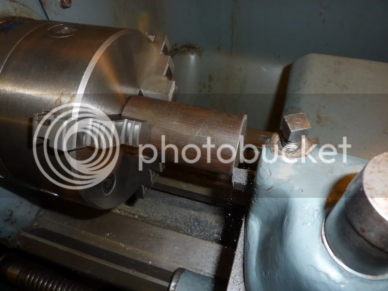
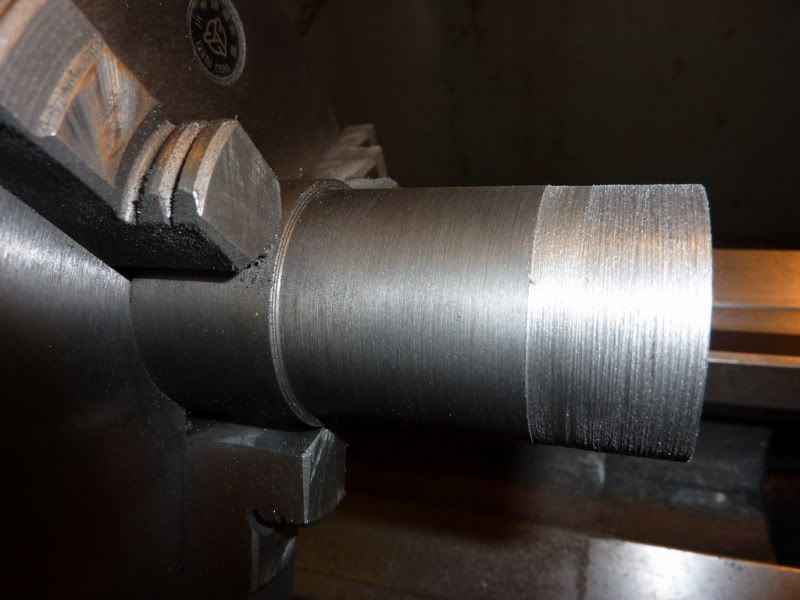
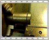
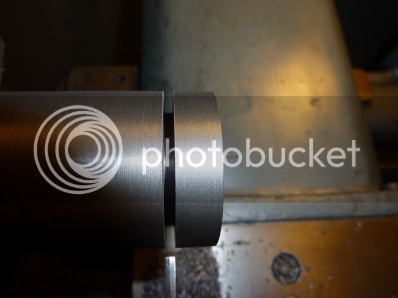
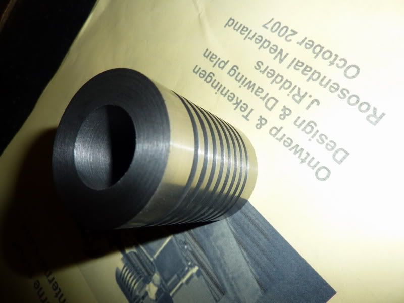
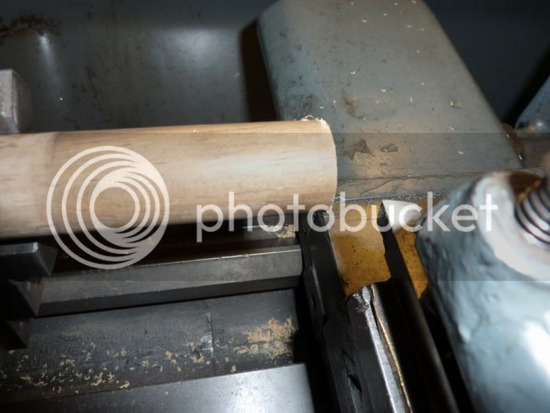
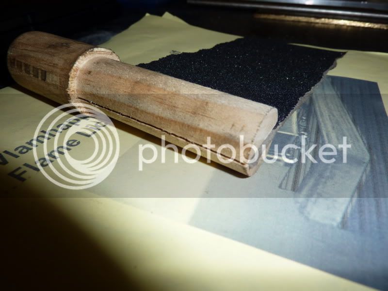
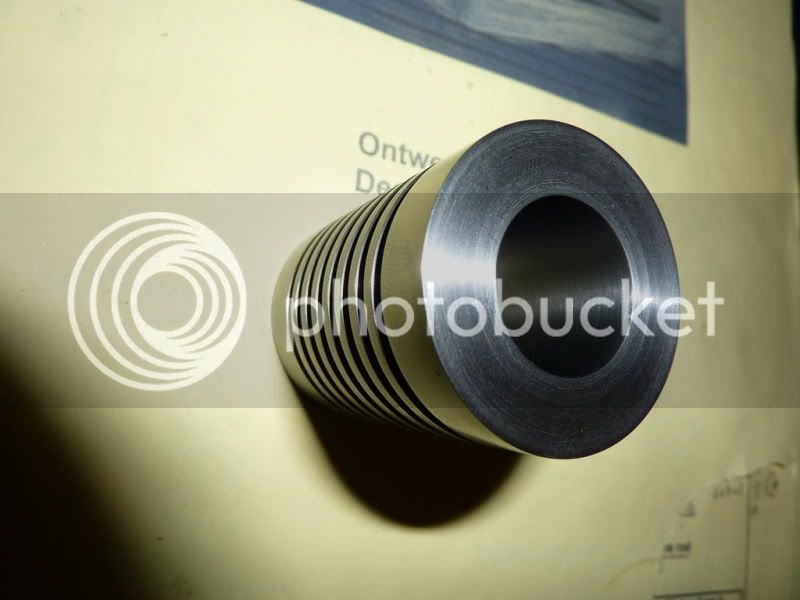
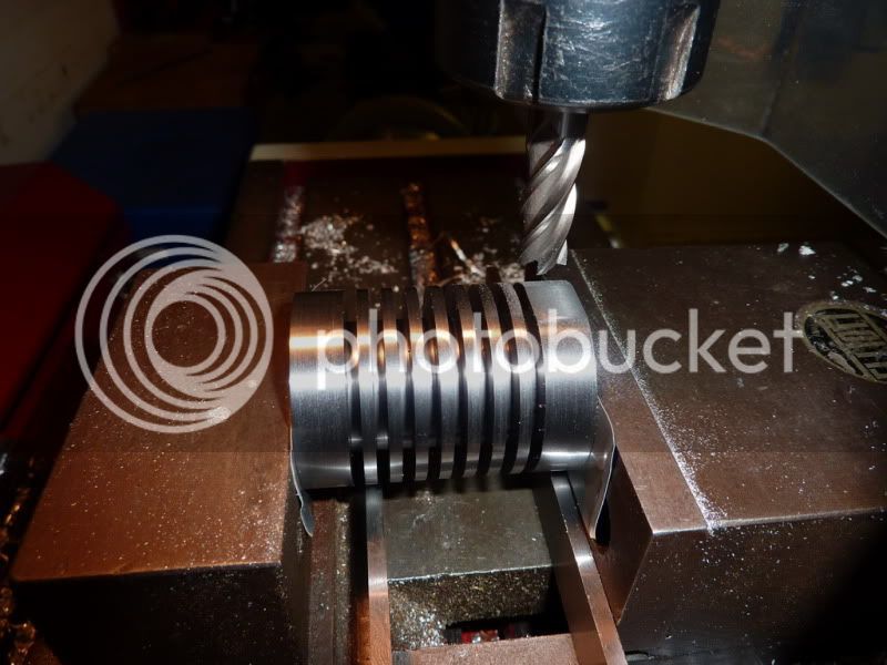
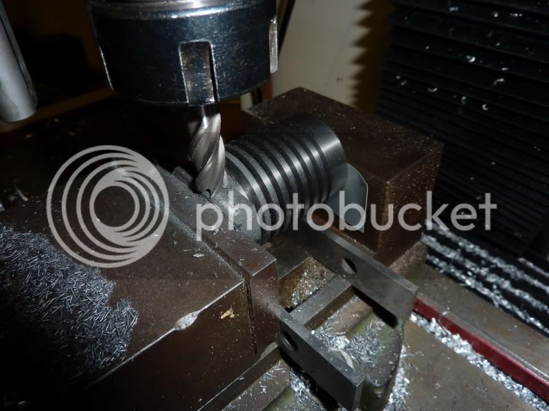
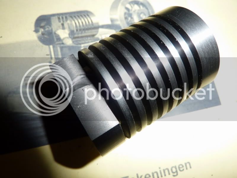
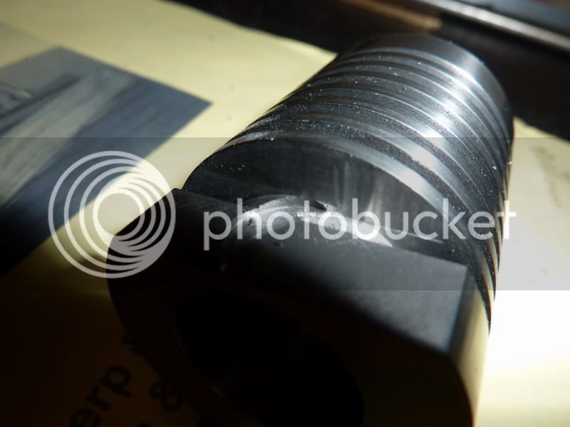
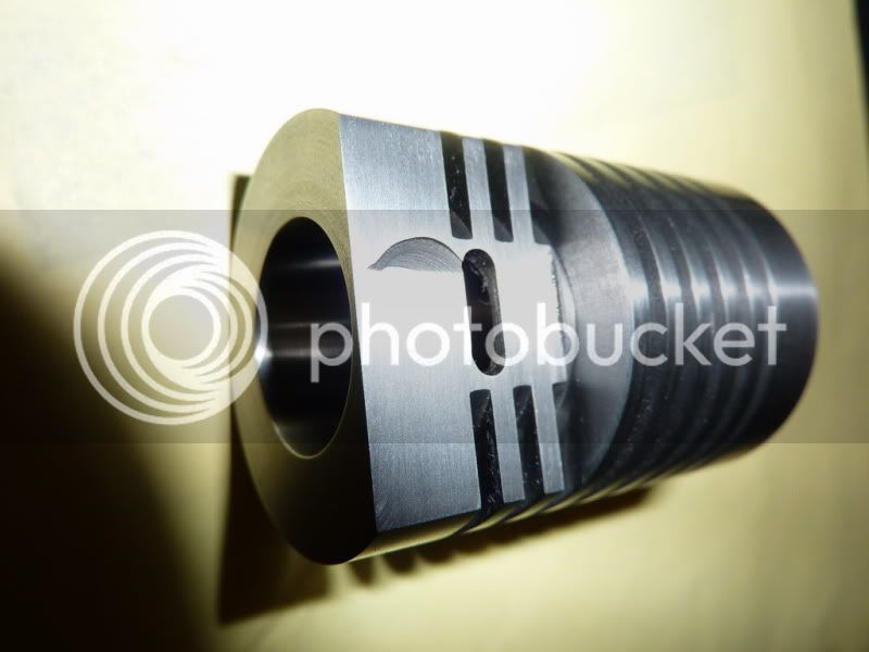
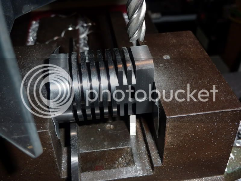
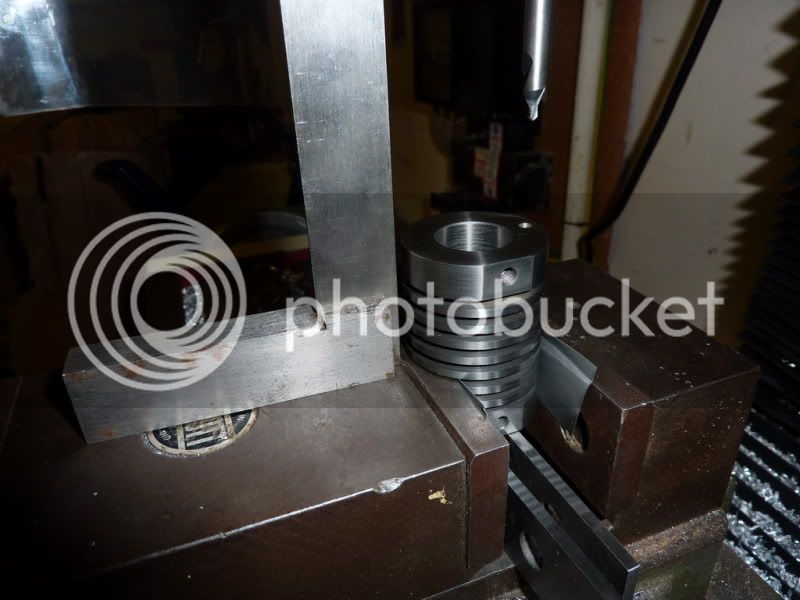
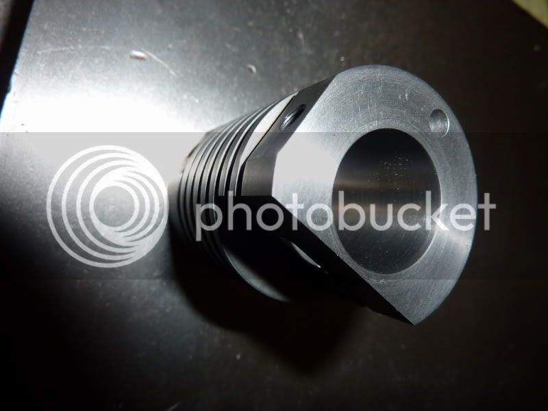
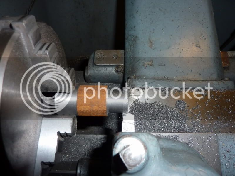
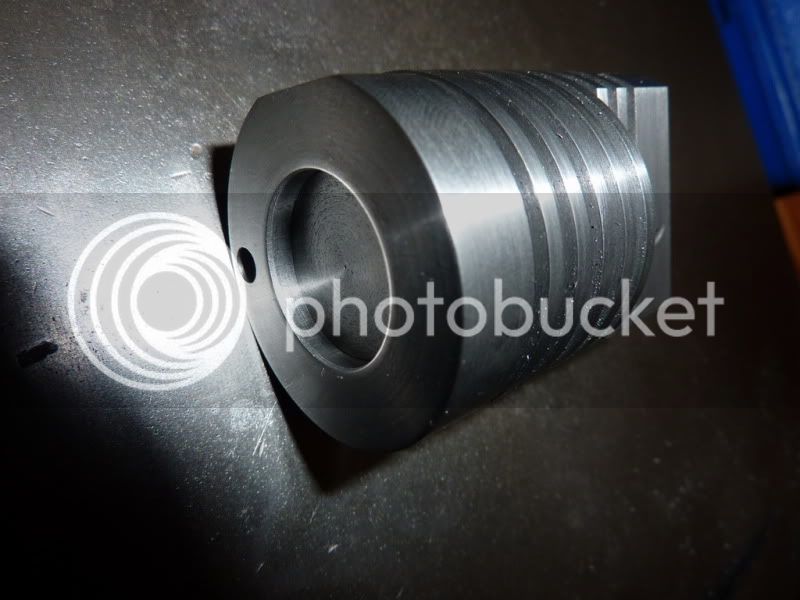
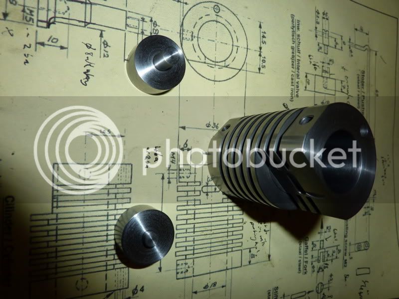
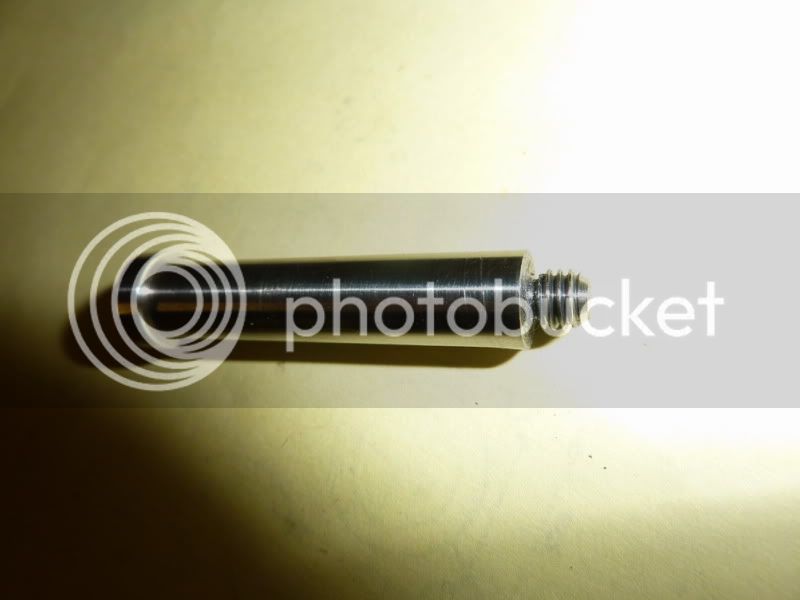
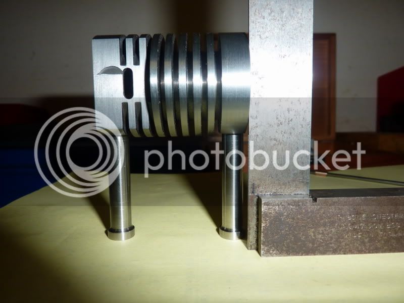
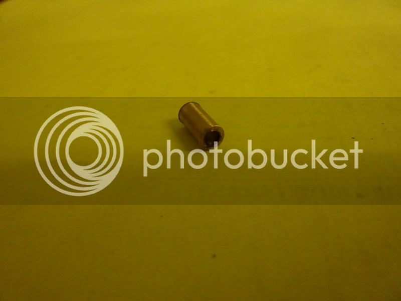
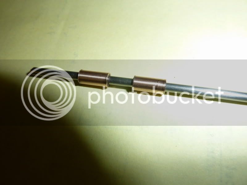
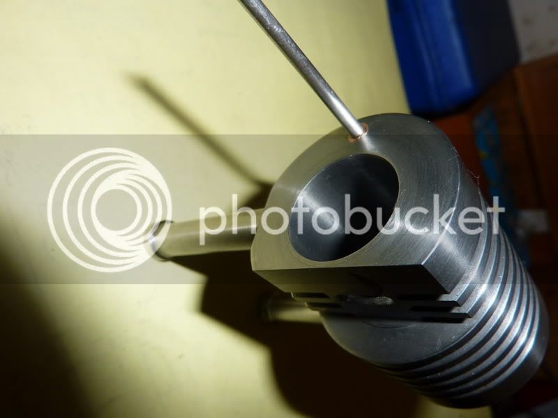
Here are some of the materials:
2009-11-0220-17-15_0001.jpg


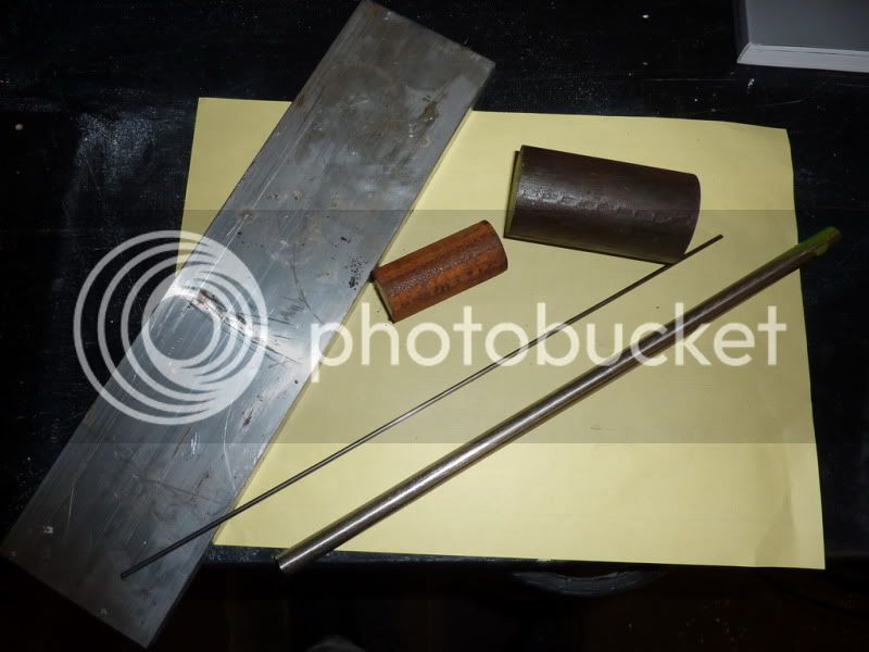
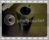
Any ideas? This pic might give a better clue:
2009-11-0220-17-31_0001.jpg


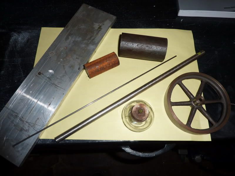
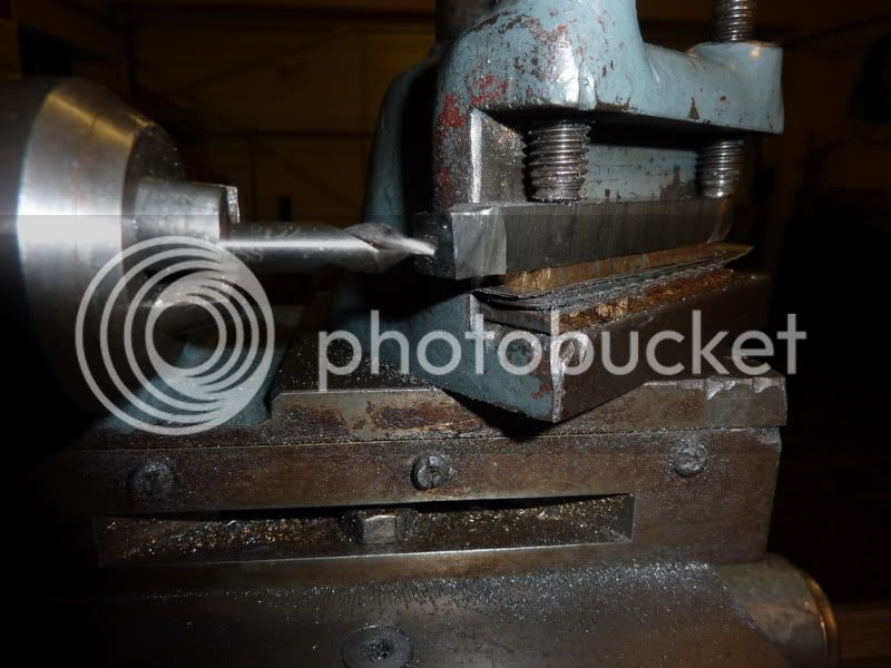
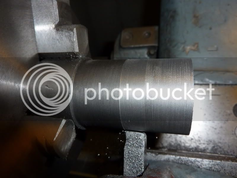
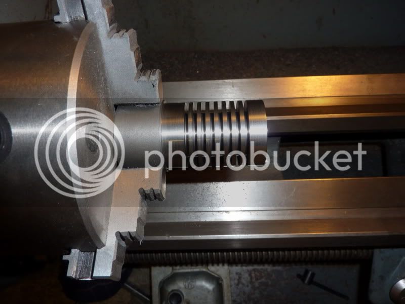
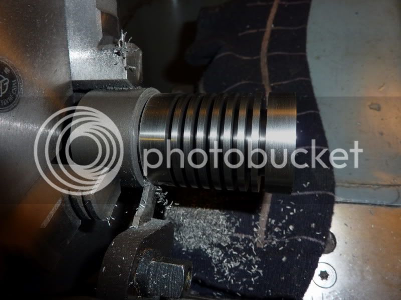
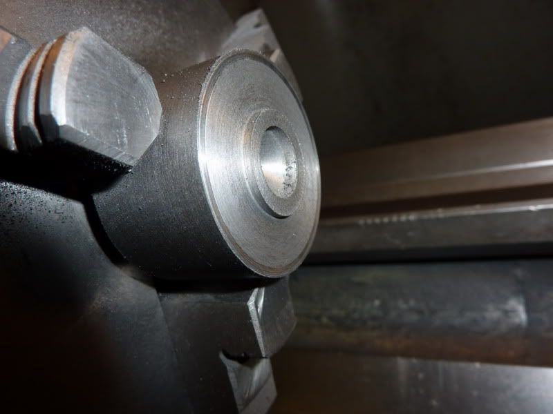
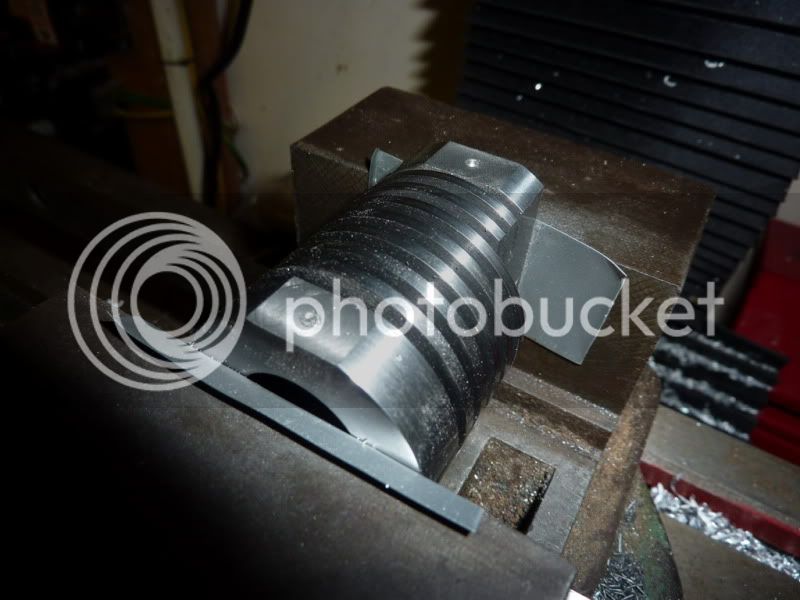
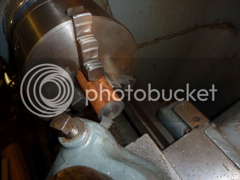
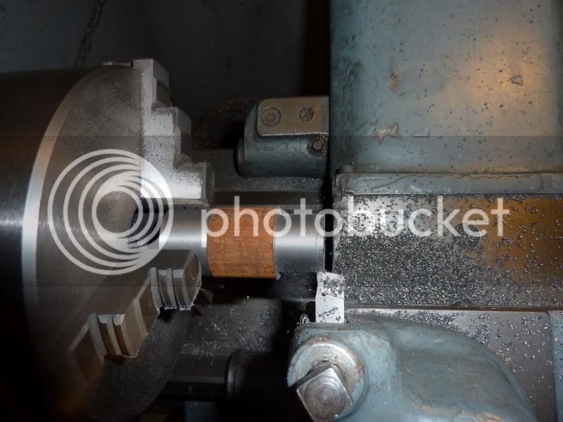
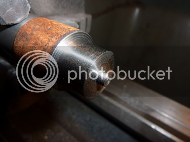
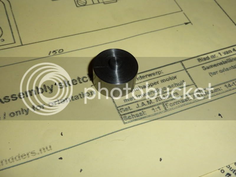
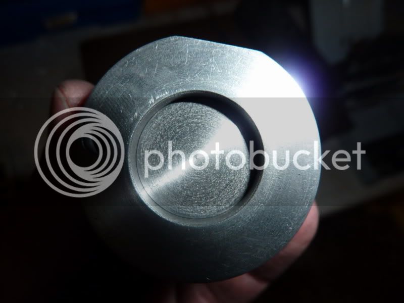
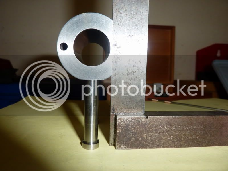
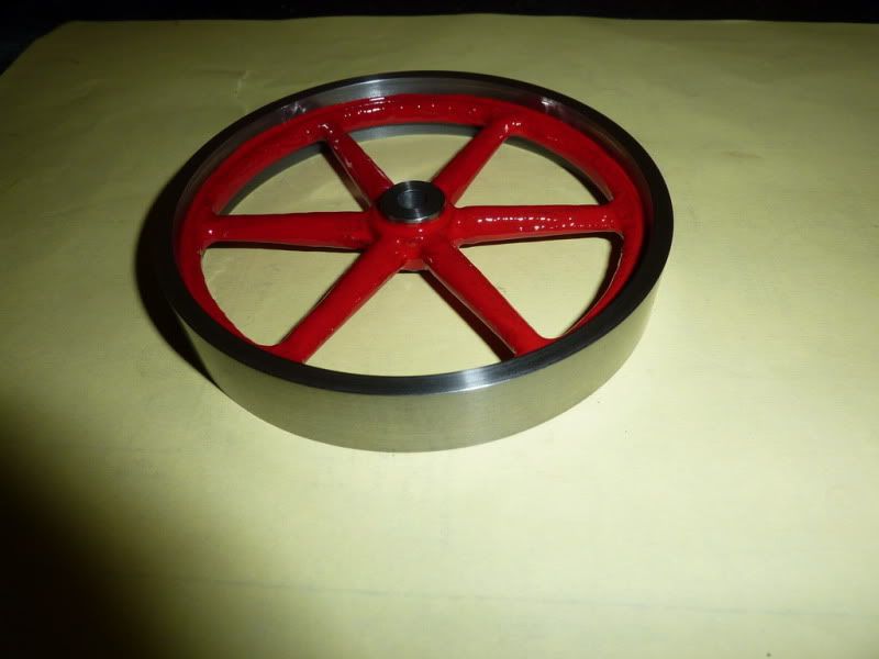
The wheel was an old casting I got many years ago and machined quite badly but never used it on anything. I thought I could probably put it to some use now so I set about trueing it up in the lathe.
2009-11-0220-59-28_0002.jpg


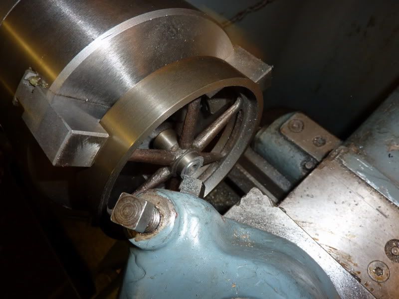
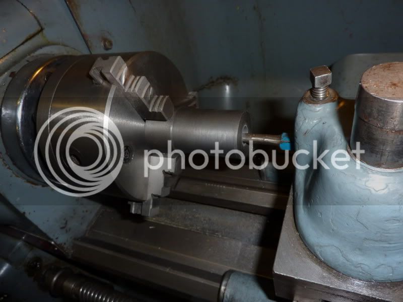
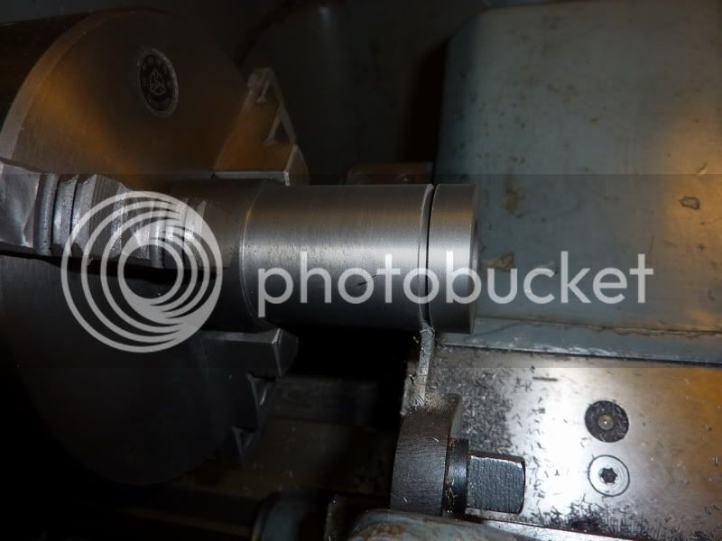
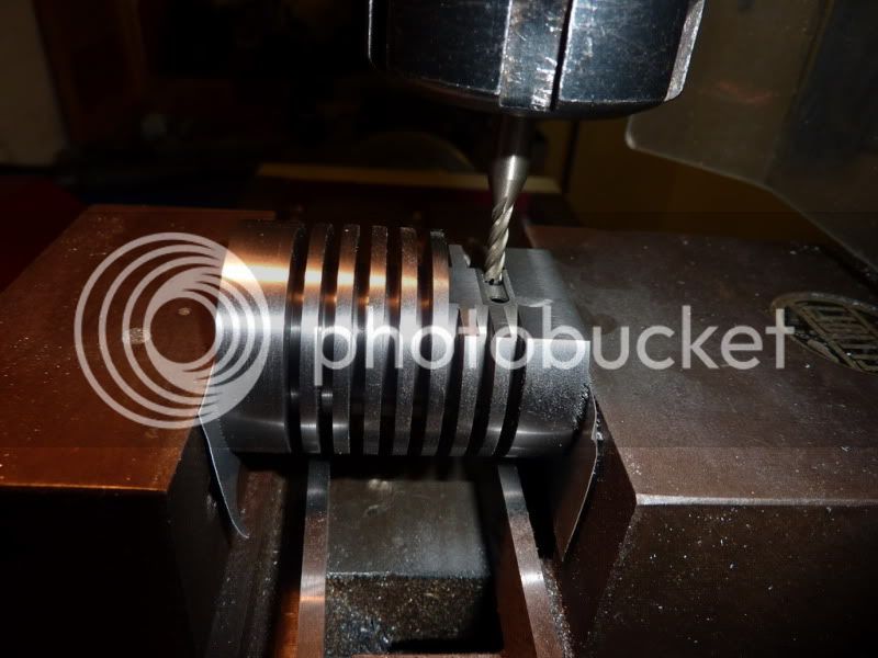
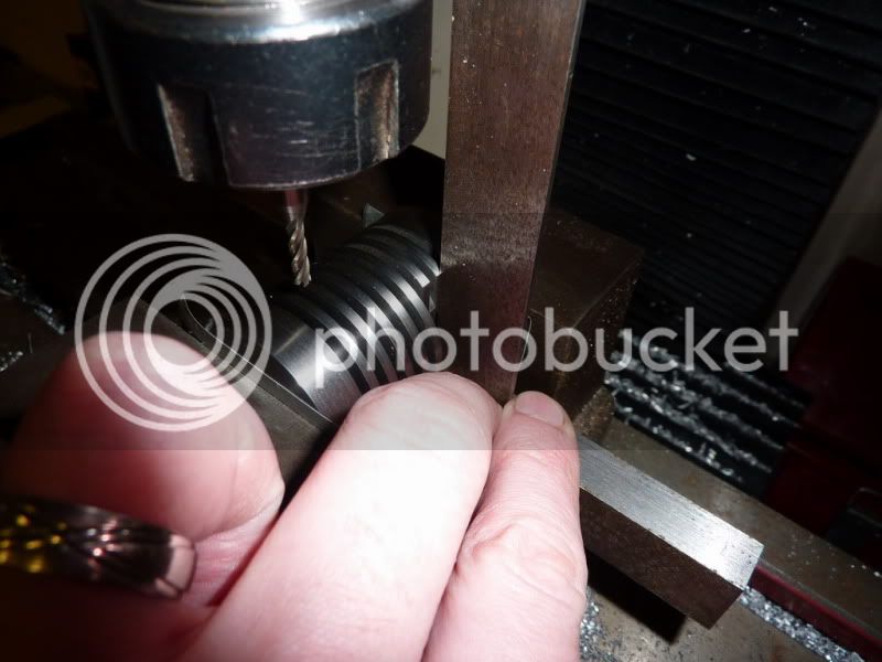
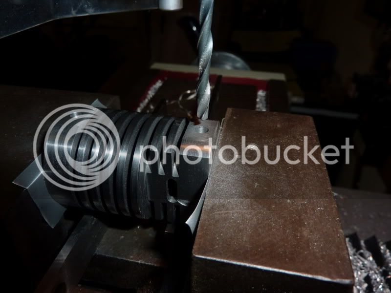
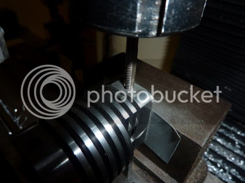
Not quite finished, it'll need drilling and tapping for a grub screw.
2009-11-0223-05-28_0003.jpg


That's all I got done today, I couldn't do the morning session due to other things getting in the way. I am going to do my best to make sure nothing else gets in the way as otherwise I definitely won't achieve my goal.

Nick


A few other members will know I've been banging on about making a flame gulper for some time now so this is going to be my attempt! It's going to be based pretty much on Jan Ridders internal valve one just with a few simplifications. I was planning to do a 3D model and draw it up on CAD but that would take some time and I have a good opportunity to get in the workshop this week, so I'm keeping most of his parameters. A few things will need to be altered to accomodate the flywheel and burner though which will save me some time.

For about the first time ever I've actually been and bought some materials for this project, they normally come from off-cuts of scrap I've collected over the years but I thought I don't have much time to mess about.

I went to a local model engineering material supplier - I only found out this place was about 7 miles from me a couple of years ago but have never been. The materials in the first photo cost £12.50 which I thought was reasonable. 3/8" x 3" HE30 alloy, 40mm cast iron, 25mm cast iron, 2mm stainless and 10mm stainless. Just about to order my bearings from Arc Euro Trade, hopefully postal strike won't affect their delivery!

I just hope it works. I managed to make a working stirling engine but I think I'll need to pay more attention to the fits on this one.

Nick
 
Build is going slowly! Everything on this engine is bigger than I am used to so the metal is taking longer to remove! Also, I keep getting interupted, we bought a new bed at the weekend, but it doesn't fit in the current place in the bedroom so I said I'd move the fitted wardrobe to another wall - I meant eventually, not before the bed is delivered! Wife and parents seemed to have other ideas and the wardrobe has now been ripped out, which means cobbling together laminate floor (where bits are missing underneath it) and the room will need repainting after - stupid bed!

I did get a bit done yesterday though so pics to follow...

Nick
 
Never mind, I'm back out there after I've written this little bit up. I can't even do my write up after the workshop session since we're sleeping in the spare room where the computer is and the wife complains the typing noise keeps her up! :bang: can't win!

Anyway, yesterday I decided to make a start on the cylinder since this is probably one of the more complex parts on this engine.

I started by skimming 1 end of the lump of cast iron to give me somewhere true to grip:
2009-11-0314-41-26_0001.jpg

2009-11-0314-45-36_0002.jpg


Turned around in chuck and the OD rough machined down to 0.5mm oversize. All the dimensions for this are metric so am having to do a bit of conversion with the dials. I actually think I prefer metric sizes now, it’s just most of my stuff is imperial. Might adopt the new system! Also centre drilled and drilled straight in with ½” drill (biggest I have) to a bit longer than the required 50mm depth.
2009-11-0315-37-38_0003.jpg


Bored the hole out to size. This took a while as I only have a crappy TC tipped boring tool which isn’t very ridid. I have a big boring bar too but I don’ t think it fits in the tool post and is too big for this bore in any case. Finish wasn’t amazing as the tipped tool has a chip out of it but not bad considering.
2009-11-0315-55-35_0004.jpg


Decided I would finish turn the OD at this stage, back to a nice slow feed. So why am I getting such a crappy finish now when it was OK before?
2009-11-0321-17-02_0005.jpg


Was just about to start pulling my hair out when I thought I’d re-check centre height:
2009-11-0321-18-01_0006.jpg


Only about 3/16” too high! I’d used the same setup plus the bit I used for the boring bar! That could be why! Finish much better now that’s corrected:
2009-11-0321-21-37_0007.jpg


Next comes the scary bit – putting the grooves in, only it’s not actually scary anymore on this lathe – at least not on cast iron, brass and aluminium. I am deviating from the drawing here in 2 ways. 1. I just made the grooves the width of my parting tool (happens to be 2.15mm) and calculated how many would fit, and 2. I made them 6mm deep instead of 7mm as I went oversize on the bore by 1mm.
2009-11-0321-43-56_0008.jpg


Parting off at about 200rpm under power.


Finished groove, worked really well.
2009-11-0321-45-50_0011.jpg


I was going to stop for a break ½ way through as I thought the tool would be getting red hot, but it wasn’t even warm. The cylinder was luke warm so I just continued. Here it is with all grooves cut and a bit of a de-burr and polish.
2009-11-0322-28-47_0014.jpg


Parting off leaving 0.25mm to skim off other end:
2009-11-0322-37-09_0012.jpg


Why is it I mess about with all these tools to get a good finish and the best bloody one is the parting tool?!
2009-11-0322-40-02_0013.jpg


This picture shows that I only JUST drilled and bored the hole deep enough! Lucky there.
2009-11-0322-42-25_0015.jpg


I don’t normally bother lapping the bores on my little steam engine and didn’t on my hot air engine, although I tried to ream that one I didn’t lap or polish the piston. But on this one, I thought I’d better pay more attention to the finish of the bore and pistons if I want it to work. So I chopped a bit off the brush handle and turned it down to a bit under the bore.
2009-11-0322-58-50_0016.jpg


Then put a saw cut down the middle and wrapped some wet & dry around it. Medium then fine then fine with oil.
2009-11-0323-07-43_0017.jpg


Seemed to work a treat, well happy with the result. Back off into garage now to hopefully finish the cylinder. Didn’t get my morning session in due to stupid bedroom!
2009-11-0323-18-50_0018.jpg


So far I am trying to pay more attention to detail on this project, and I am using known materials. Hopefully, if I can keep this up it will turn out to be my best one yet. I just hope it will work, fingers crossed!
Nick
 
So, I'd done what I thought was the hard bits on the cylinder so I clamped it in the vice on the milling machine and started machining the flat for the intake port. I used a brand new cutter to give me a good finish and it was going well:

2009-11-0422-03-23_0001.jpg


NickG said:
So far I am trying to pay more attention to detail on this project, and I am using known materials.

:doh: :bang: :(

That must have been tempting fate!

This happened:
2009-11-0422-19-35_0002.jpg

2009-11-0422-21-11_0003.jpg

2009-11-0422-21-37_0004.jpg


This was caused by the vice not being tight. I'd got down to my 7mm depth 1 cutter wide and I thought instead of doing all that again it would be easier to control if I now used the side of the cutter to cut where I wanted to in the Y direction. As soon as I tried this the thing slipped and dug in. The vice felt nice and tight, the only thing I can think is it was it was at it’s extreme of opening so I didn’t have much thread engagement and it wasn’t actually tightening, just causing damage to the thread. Will have to strip the vice down to find this out.

So the rescue mission started with taking the jaws off the vice and clamping, this time it did tighten and I was able to half-save it. The wall is a little thinner than it should be and there is still a fair of a divet out of it so am a bit gutted, but it should still function.

All I did after this was cut the port, which actually turned out slightly bigger than the 3mm it should have been. I guess I shouldn’t have used a 3mm end mill! Or maybe I could have got away with it if I hadn’t drilled a hole at each end first. I will need to make sure there is enough meat on the valve to let it close fully but it should be easy to adjust.

Cutting the port.
2009-11-0423-38-02_0005.jpg


How it looks now.
2009-11-0423-49-50_0006.jpg


Still a bit of work to do on this - Two small flats need milling for the pillars, then drilling and tapping. Then drill the long hole drilling 4mm and turn up bronze bushes for each end.

There’s no point trying to rush this, it’s definitely not going to be finished by the end of the week and if I do, other errors are likely to happen! Realistically, the end of next week is now the aim but I’m not going to get myself beat up about it, if it doesn’t happen –tough!

Nick
 
Right, will post last night’s progress. This was basically finishing off the cylinder, that is, milling the two flats + drilling and tapping for the pillars and drilling the long hole for the valve rod.

Setting up perpendicular to the port face to mill flats:
2009-11-0522-14-46_0001.jpg


Flats milled – nearly took 2mm off but thought it look enough when I got to just under 1, so checked the drawing again and it was infact a 1!
2009-11-0522-24-45_0002.jpg


Holes centre drilled:
2009-11-0522-54-11_0003.jpg


Opening up to tapping size – changed this to 2BA which was nearest I had to 4mm:
2009-11-0523-05-12_0004.jpg


Tapping – was thinking of doing this under power but leaving it not too tight in the collet so it would slip. Chickened out though and turned the spindle by hand! I was always taught to go 1 turn forward ½ turn back anyway.
2009-11-0523-14-20_0005.jpg


Set up to centre drill and drill the long hole. I used the square just as a check that it was clamped correctly.
2009-11-0523-47-53_0006.jpg


It worked really well with the 4mm drill, didn’t seem to wonder off at all, it’s come out spot on.
2009-11-0600-00-20_0007.jpg


The only thing was, there was something funny happening with my milling machine when drilling that long hole. It felt like something was binding, either the spindle or gears the further down I went on the travel. Will have to look into that, I know the guy that bought the same one at our club has had trouble with his so will have to investigate.

Right off to attempt the piston / valve now I think!

Thanks to all for your interest, support and advice. :bow:

Nick
 
This instalment covers the pistons, or piston and valve.

I started off in the same way as the cylinder and trued up the cast iron:
2009-11-0621-33-27_0001.jpg


Turned it around in chuck and started whittling it away nearly down to size:
2009-11-0621-47-08_0002.jpg


Now taking finishing cuts of 0.0005” and trying in cylinder:
2009-11-0621-54-59_0003.jpg


I got so far and thought right, it’s time to start lapping. I just did that with some wet & dry wrapped around a bit of square tool steel.
But it still didn’t fit after lapping so I took another ½ thou cut off and it slid in – DOH! It was a good surface finish so need minimal lapping and I didn’t want to reduce the size any further.

Also turned the spigot:
2009-11-0622-24-25_0004.jpg


Parted off:
2009-11-0622-47-18_0005.jpg


Am not that confident it’s a good enough fit, feels a bit loose so am thinking I’m probably going to have to re-make it.
2009-11-0622-52-16_0009.jpg


2009-11-0622-53-04_0010.jpg


Here’s a video of the piston sliding down with the cylinder resting on the surface plate, trouble is, the surface plate isn’t that flat so air will leak around the cylinder. If I put my thumb in the end and form a tight seal the piston stays pretty much where it is until I remove my thumb. So it might work, I’ll give it a try but I’ll know the first place to look if it doesn’t!


I also made the valve for the back end of the cylinder. I thought with this one I won’t make the same mistake twice, I’ll measure the bore and aim for maybe 0.1mm over then lap the rest until it fits nicely. Only got down to 0.1mm oversize, it wasn’t – it slid in again so I had to do minimal lapping to avoid making it much smaller. I have about the same fit on both pieces now.

2009-11-0623-47-46_0008.jpg


Just need to drill the cross hole in the valve for the valve rod (slightly different design to Jan’s, I just incorporated it into 1 turned bit). Interestingly, Jan calls for a 2.3mm hole with 2mm rod. Wonder if this somewhat sloppy fit is just to stop things binding?

On the piston, I am going to do it the same way as my hot air engine. Mill a slot into the cast iron and cross drill right through. The pin will be a nice sliding fit in the cross-hole but a tight fit in the rod, thus will be held in the middle to prevent scoring of the cylinder walls.

So I’ll finish those off, make the little bushes, valve rod, adjuster and pillars then that’s the cylinder and pistons complete. Still have the base plate, crankshaft, conrod and bearings to do. Who was I trying to kid doing this in a week?!

Nick
 
Due to the bedroom obstacle and a cold starting on Sunday the only thing I've managed to do on this was 1/2 a cylinder pillar ... wasn't even worth taking a pic of. Just realised I'm taking lots of pics of straightforward turning which is pretty pointless after the first one! I am machining these from 303 or 304 stainless (can't remember which the guy said, but it is free cutting which ever that is!) It machines really nicely and leaves a superb finish.

The good news is, the bedroom should be finished by Friday and my cold should have eased off so I should be able to restart this project.

Have been thinking about what I need to do and wondered if it's worth getting a length of 6mm silver steel for the crankshaft and 3mm for the crankpin because it's usually a nice ground finish. got a couple of questions on this though

a. Will 6mm rod be a good fit in the bearings? I would have thought if size for size I'd have a job getting it through!

b. does silver steel silver solder ok or would I be best going for mild.

Nick
 
Hi all,

I've finally found some motivation to pick this project back up. The week I had on leave was ruined by the bedroom redesign and at the end of that weekend we all caught some sort of cold but this wouldn't shift. Still got remains of it now nearly 2 weeks later which is pretty rare for me. I tried a couple of times to go into the workshop but I simply didn't have the energy. Anyway, tonight I felt full of life and enthusiasm which was good!

Tonight's job was the two cylinder pillars, I'd already made a start on one but didn't take any pics of the machining, it was straight forward turning, the critical dimension from the base to the thread shoulder. As long as it's high enough to give the flywheel clearance, they are both the same and I make the bearing blocks the corresponding height that is all that matters. Also getting the thread straight was critical.

Here's one of them.
2009-11-2100-02-57_0002.jpg

The one thing I am doing is getting better at forward planning with the more experience I get. At one time I wouldn't have put undercuts on and chamfer on the end of thread then I'd wonder why it wouldn't screw all the way home. I tried to part this stainless off but didn't like the noises coming from it so chickened out and sawed them off, turned them around and faced to length. For the undercut I used a hacksaw as again, the thin grooving tool was having none of it. I think I'd ground it from a bit of duff HSS that I had overheated at some stage by grinding too hard as it was all blue / brown colour.

Pretty chuffed with the result, everything looks very square.
2009-11-2100-08-37_0003.jpg

2009-11-2100-09-04_0005.jpg


This meant I had time to turn the bushes for the valve rod. Luckily I found some bronze (I think) off some old balance scales which was almost the right size. Carefully turned it down to size and drilled it.
2009-11-2100-05-34_0007.jpg

My valve rod is actually 3/32" not 2mm so just got the nearest oversize number drill and it gives a nice sliding fit.
2009-11-2100-07-25_0001.jpg


Here they are assembled, rod was marginally tight at first but a few strokes up and down and it’s a lovely sliding fit now, drops through but doesn’t wobble.
2009-11-2100-14-17_0008.jpg


I may need to loctite these in as it was more of a push fit than a tight press fit.

Am very impressed the way this has gone so far. Apart from my blunder on the cylinder, it’s gone very well so I am just waiting for something bad to happen! The pistons may not be a good enough fit yet though but they are fairly simple to remake if need be.

Next on the list is the valve rod, drill the hole in the valve and the rod control at the other end.
Then finish the piston off, bearings, conrod, crank and base!
Still a long way to go, I don’t know why I am so optimistic with timings when I start out, you’d think I would know by now!

Nick
 
Really good documentation, Nick. It looks like it's going very well with the exception of the bedroom problem.
Very glad for you that the milling doink incident didn't ruin the cylinder. There's a lot of work in that!

Dean
 
Great documentation and photos Nick. And really nice work. I'm looking forward to your next installment.

Rudy
 
Thanks Zee, Dean and Rudy,

They are great looking engines in your avatar's by the way guys.

Yeah, I was gutted about the cylinder slipping in the vice and was glad I could rescue it to some extent. It will probably always annoy me although it will get sutted up a bit and I guesss it shows a bit of a story and I can put it down to experience!

Ok, positive thinking over ... I'm off for a good :'( :'( :'(

Nick
 
The project is coming along nicely Nick! ;D

From your description of the piston fit, and the fact that it will not drop through the cylinder if the ends are sealed, sounds like it should run OK. You want as little friction as possible, but as air-tight as possible. Seems like you have hit the target spot-on!

Well done for persevering with the cylinder after the 'accident'. I would end up making another after the damaged one went on a little 'journey' to the end of the garden. :big:

Anthony
 
Thanks guys,

The cylinder very nearly did become embedded into the garage wall but I held back, it was probably the best bit of work I had produced until then!

Not sure on the pistons Anthony, they're a better fit than in the hot air engine I made and that worked, but still not sure whether they are good enough. Especially the valve as I'm told you can't run these things with oil or they get gummed up. With the stirling I put quite a bit of oil on the power cylinder and displacer rod to help seal. As you say though, it's a fine balance between the best seal and low friction. If I wasn't so impatient I could have got closer by spending more time lapping. We will see, at least I'll know where to look first when trouble shooting. If I can keep everything nicely alighned from now on, the pistons should be the only possible issue. Mind you, that's easier said than done!

No progress tonight, the wife is of out to watch some daft film so I better not get lost in the workshop zone incase the kids wake up or something (god forbid)!

Nick
 
Hi Nick: The only people who don't make mistakes are the ones who are not doing anything. Your project seems to be coming along nicely.
Jack B
 
Cylinder seems OK to me mate!!!
No worries.

The little sod will run or else...

excellent post, crisp photos, nice and clear writeup. Inspiring.
I'll be following.

tom
 
Thanks Jack and Tom, much appreciated. I really hope I can get it to run, I won't give up if it doesn't as it's now a pretty recognised design so there should be no excuse for not getting a runner - talk about shooting yourself in the foot - ouch!

The only reason for the decent photos is because my wife wanted a new camera to take photos of the kids etc. We were looking at DSLR's but that looked an expensive hobby to get into so we went for a more practical top end compact thing. It's good, everything I take is just done in intelligent auto mode, when I try to mess around myself they don't come out as well. Probably because I don't know what I'm doing!

Some of the photos people post on here though are truely amazing, hats off to those guys who produce excellent work as well as magazine quality write ups and pics.

Nick

 
Looking great Nick!!! I built a Fire eater. It always ran great, After, It was warmed up. The trouble with them is that they barley make enough power to run themselves and any friction at all will make them problematic. I had an Idea to make a piston out of Graphite. The one I made was what I thought to be just a little too lose. But, It works better that ever. Usually it will even start on the first flick. I think the self lubing graphite was the ticket.

Can't wait to see the rest, Wes
 

Latest posts

Back
Top