Hi Darran and Ogaryd,
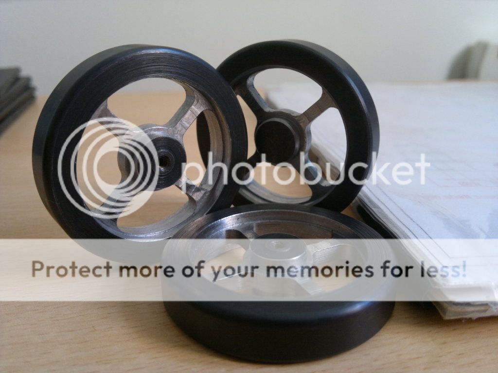
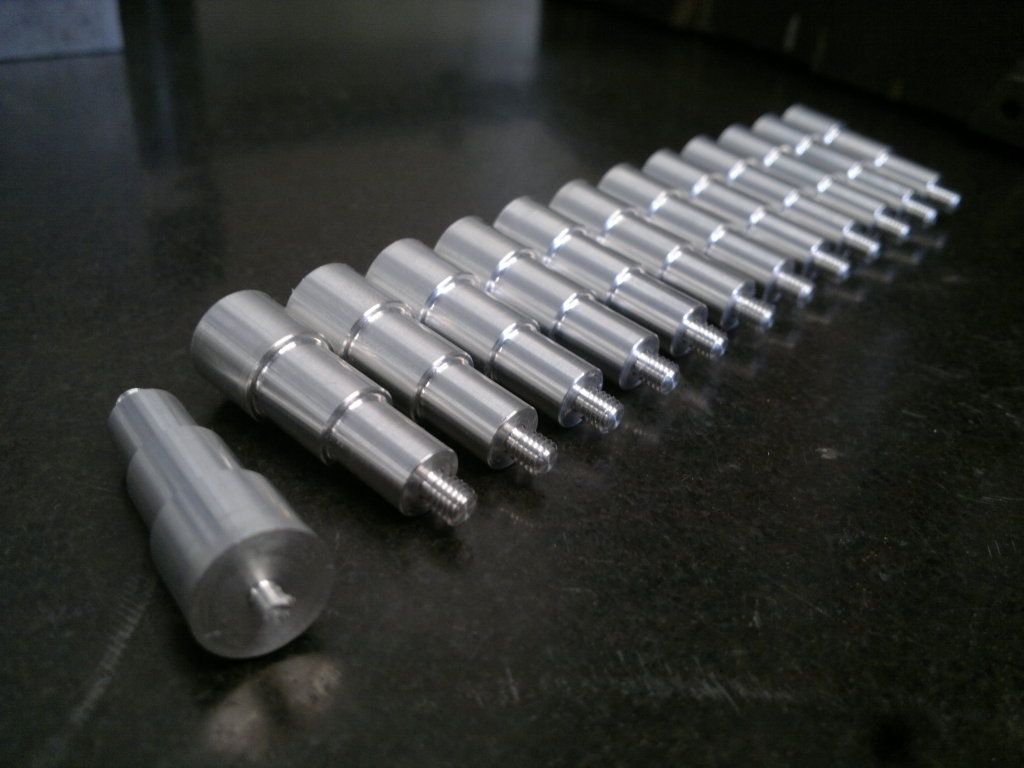
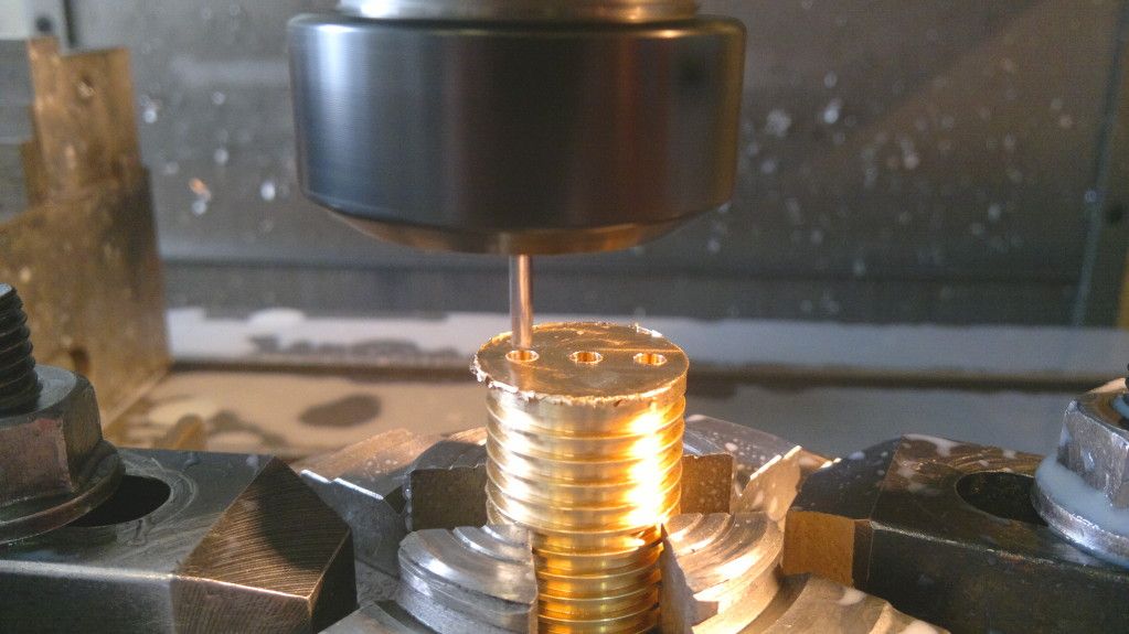
I got my stirling 60 running last weekend. Although machining was finished several weeks ago, I just would not run more than a few turns.
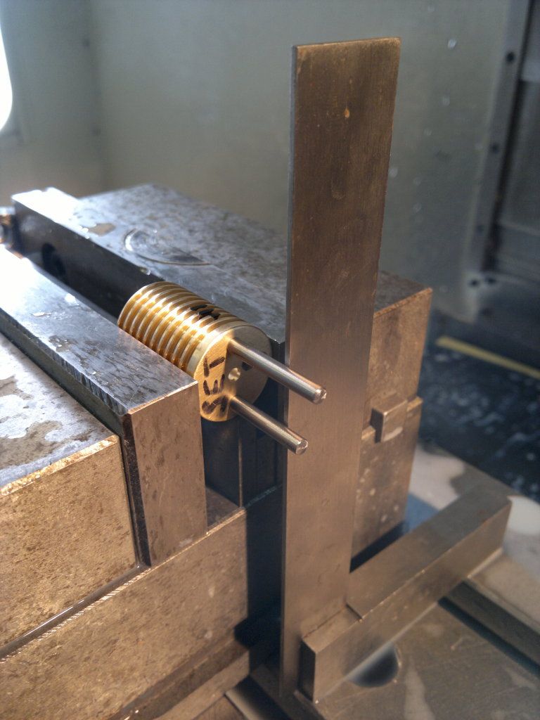
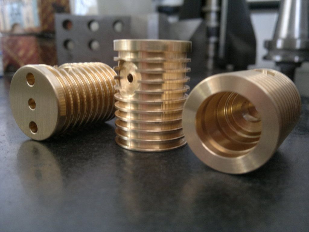
Finding the problem took me a lot of playing around. The first problem was the friction of the displacer rod (polished silversteel) in the reamed brass bushing. I did not use cast iron as mentioned in the plans as I did not have cast iron at the time. When I enlarged the hole in the brass, the friction was reduced a lot without loosing the air-tightness, but now the rod was able to tilt in the bushing and the displacer started to touch the side of the testtube. Now the engine ran a few turns more than before but still not continously.
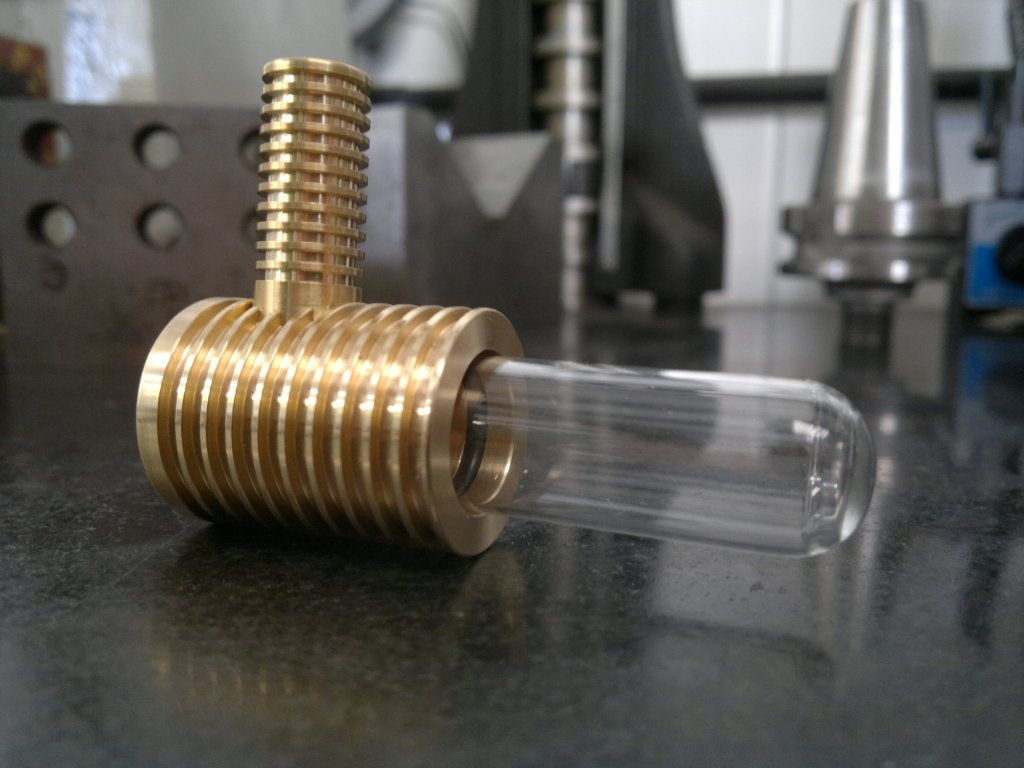
Finally I replaced the brass bushing by one made from teflon. The hole, through which the displacer rod runs, was drilled with a smaller diameter and 0.5 mm out of center to avoid the displacer touching the side of the testtube. Even with the reduced diameter of the hole, the displacer rod runs virtually without friction and the out of center gives another 0.5 mm clearance to compensate for the small amount of tilting of the displacer rod. Now the eninge runs pretty fast and continously using only a small flame as is should.
cheers,
Xander


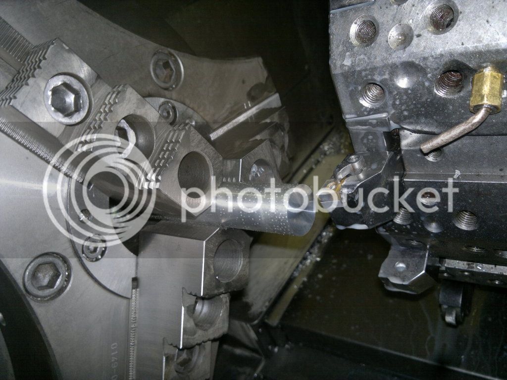
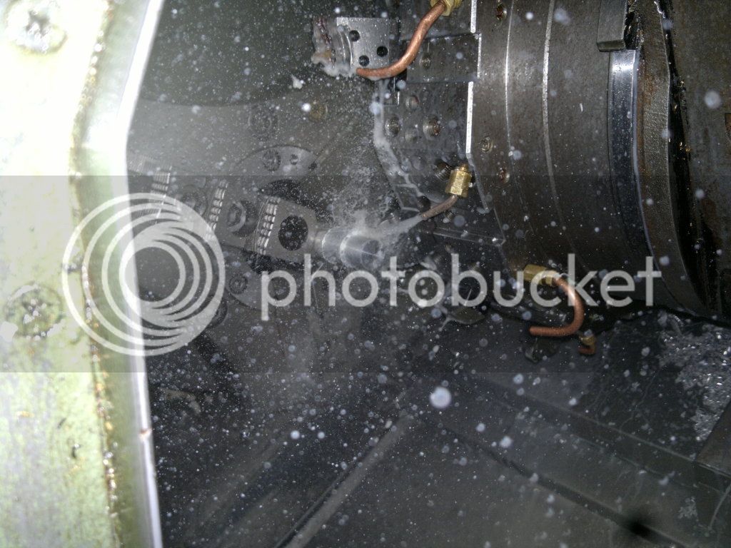
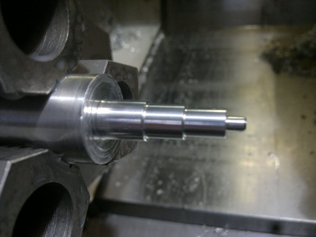
") Are you using CNC? your progress so far looks great
Are you using CNC? your progress so far looks great