My first engine Stirling 60

Home Model Engine Machinist Forum

Help Support Home Model Engine Machinist Forum:

This site may earn a commission from merchant affiliate links, including eBay, Amazon, and others.
Joined
Apr 27, 2012
Messages
70
Reaction score
8
After looking around the site, asking a few questions and searching the net I've decided to make J. Jonkman's Stirling 60 as my first engine.

Had a hunt around the workshop today and found some materials so I made a start.

hardinge.jpg


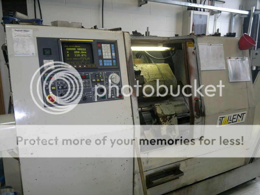
this is the smallest lathe i have at work so this is what I'll be using for most of the turning work


haas.jpg


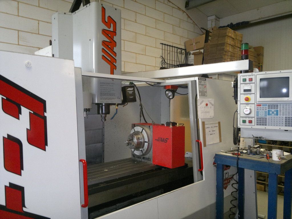
This is what I'll be using for most of my milling


partturned.jpg


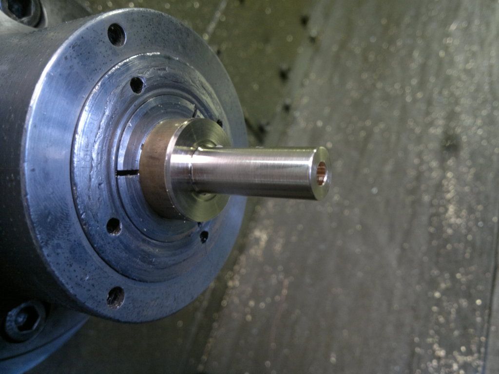
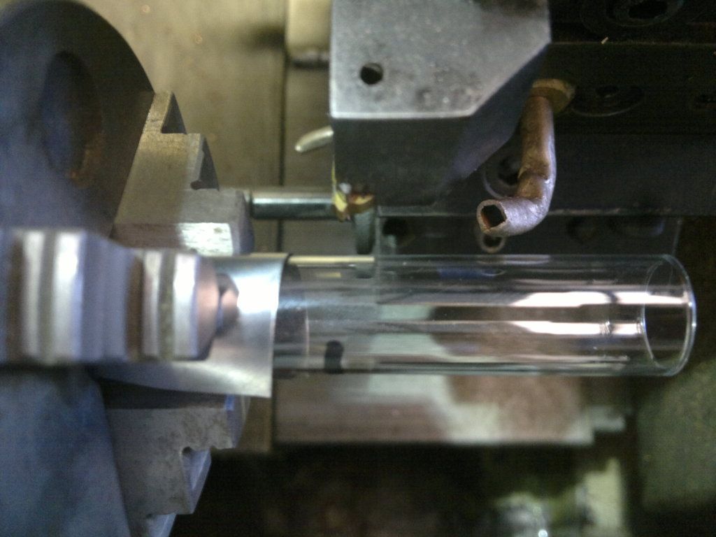
power cylinder after turning and with bore


withgrooves.jpg


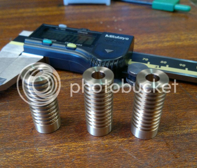
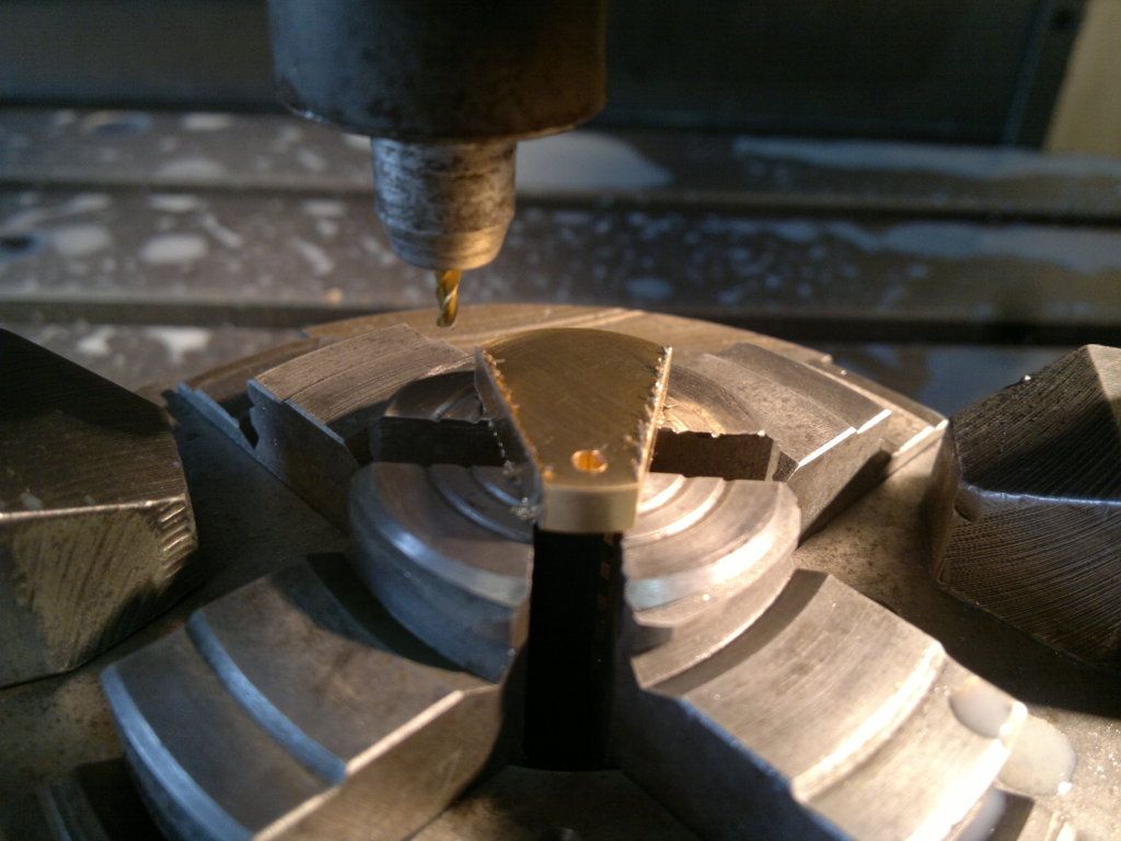
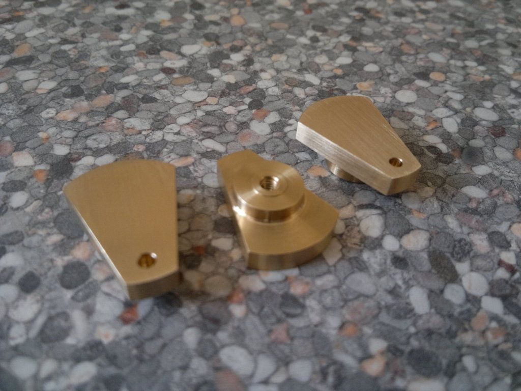
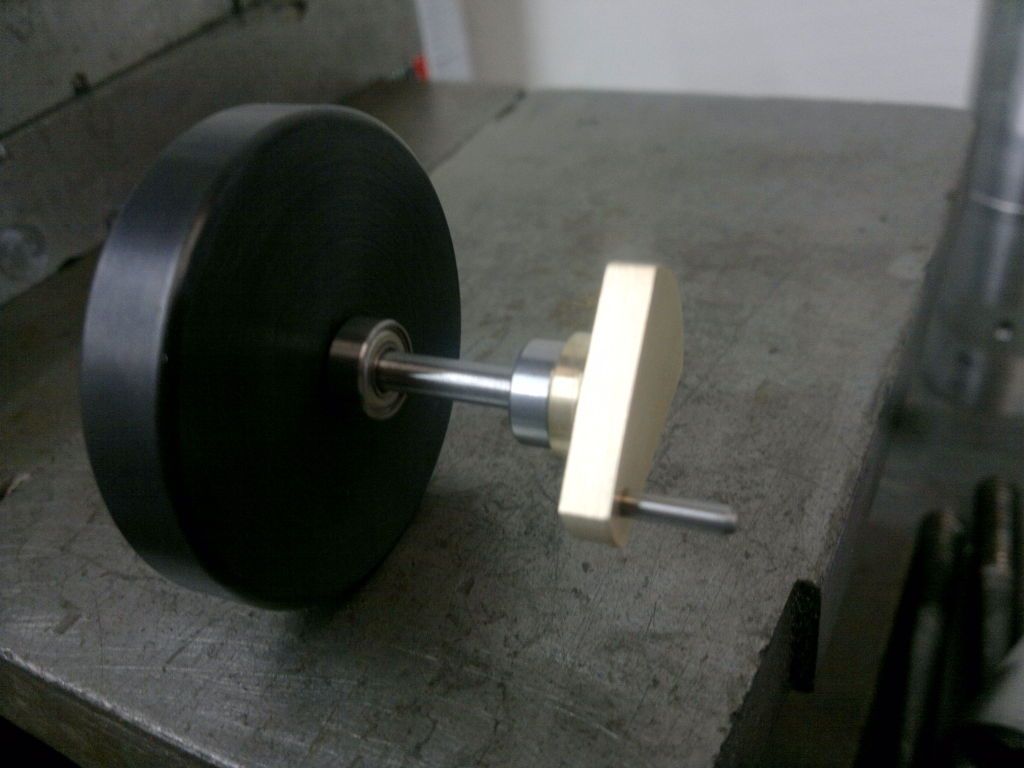
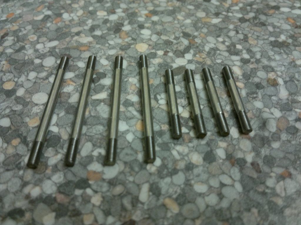
My first finished components of the project, I'm getting a bit excited now!

You'll have to excuse the large pictures, can't work out how to re-size pics in photobucket yet.
 
Cool - I'll be following along. Stirlings require a very high degree of precision - don't settle for "close enough".
 
I'm not to worried about the precision element of the build, I'm quite used to working with tight tolerances (+- 0.01mm).
It's more that all my machinery is not that suitable for small parts. I'm looking around for a small manual lathe to help with this.
Hopefully I can do some more later in the week when the bearings and test tubes arrive.
 
Bought my ticket for the ride!!! Thm:

I love following along with any and all Stirling builds!

Andrew
 
Bearings and test tubes on order, should be here by the weekend.

You may have noticed that I'm making three of every component, I've decided that as i have to spend a lot of time setting up the machine I may as well make three.
The first component takes hours, the next two a couple of minutes!
 
Darren English said:
I may as well make three.
If I had that equipment I'd make 5.

As my old auto-shop foreman used to say - "the might not be to the drawing, but they'll all be the bloody same !"

Just signing in for the journey - best of luck.

Ken
 
I'm tagging along on this one Darren. I don't know anything about Stirling engines, but I'd like to build one someday. This will be a fun one to watch and learn from. Thanks!
 
Ken,
I was going to make more but as this is my first engine I'm a bit worried about having loads of parts that don't fit!

Test tubes arrived today, all fifteen of them. I'm expecting to break a few. I have worked out how I'll cut them with my equipment and should be doing that this weekend.
 
If you have trouble cutting the test tubes, here is a method that works well:

1. score a ring at the cut line using a diamond wheel or other abrasive wheel.
2. touch the scored ring with something hot to cause the crack to propagate.
3. flame polish the cut end with a torch.

I've never made a sterling engine, but I have cut a lot of borosilicate glass tubing.


Managed to get the cranks turned and milled.
I think they look quite good.

I have made a few changes. The diameter of the crank pin will be 2mm now as i had some 2mm 316 laying around I could use. The drawing calls for 1.6mm brass pins but I'm sure these will work fine.

crankmilling-1.jpg


Milling using a 1.6mm cutter, I also used this to interpolate the 2mm hole for the crank pin
If anyone is interested below is the coding I used for the hole

M06 T9;
S2500 M03;
G0 X0. Y-9. Z100. G43 HO9;
Z5. M08;
G01 Z1. F300;
G01 Z-3.1 F30;
G13 G90 Z-3.1 I1.199 F20 DO9;
G0 Z5.;


And here they are finished.

finishedcrank.jpg


Brian, I was going to do something similar. Holding in a three jaw chuck in the lathe, make a score with the sharpest tool possible (probably a threading insert) then touch with a small hot flame. Watched a guy on youtube with this method and it worked very well.
 
Darren English said:
Brian, I was going to do something similar. Holding in a three jaw chuck in the lathe, make a score with the sharpest tool possible (probably a threading insert) then touch with a small hot flame. Watched a guy on youtube with this method and it worked very well.

Not a bad idea. Your are right in that you would want a sharp point. (No radius)

If you have a hand held glass cutter, you could hold that in the tool post.
 
Bearings have arrived so I can take some accurate measurements and alter the drawings.

Well this morning I thought I had better have a go at cutting the test tubes. I have ordered 15 and only need 3 so plenty of spares.
The first one, done in a couple of minutes. Well this is easy, I don't know what all the fuss is about.
Glass now all over the floor! Six broken test tubes later and I have one more decent tube finished and one which will do for setting up and testing.
I still have a few left over, I'll save them for another project.


testtube1.jpg


I used a carbide threading insert to score a line then put a flame on with a micro blow torch, it worked, kind of!
 
A method I saw some time back - score the tube like you have done. Stand it upright and fill with water to just below the score - apply heat.
I saw heat applied by wrapping a couple of turns of inconel heater wire around the tube supplied with power from a variac / step down to get the wire red hot. This to cut a 1 gallon glass jug in two - go figure.

Ken
 
Not much progress.
Because i can only use the machines at work I'm a bit limited on time.
Anyway i have booked in a job this week that needs a M3 thread on a silver steel bar, so i can get on and make all the conrods which are the same design.
 
I've done something!!

After a few frustrating weeks not being able to any of my project I found some time

get-attachment.jpg


This is the crank assembly


The drawings say to make the main shaft from brass but I thought silver steel would be better.

The flywheels have only been turned so far. I chemical blacked them to see what they looked like but they need some milling detail, that will follow later.


get-attachment2.jpg


Another change to the original drawings is the con rods. The drawing shows them as one solid part but I'm going to make them from 316 stainless rods (as shown) with brass connectors on the ends.

 
Nice to see progress - a bit here and a bit there and before you know it you're done.

Ken
 
I'm starting to build up a nice collection of parts now.

The next problem, my wife is 39 weeks pregnant so not sure when i'll get back to it. ???

Is there a record for the longest project?
 
The next problem, my wife is 39 weeks pregnant so not sure when i'll get back to it.

Is there a record for the longest project?

No worries. Take care of the family and be prepared to be distracted for the next 20 years or so lol.

As for the build it will wait till you get back to it. This is a hobby it is for fun . No time limits no deadlines.
Tin
 
Darren, congratulations on the soon to be addition to the family. As fun as this hobby is...nothing compares to the miracle of little ones....yours for now and someday as for many of us...grandkids. As Tin said, no deadlines here so take your time and enjoy the family. When you get back to the build...we'll be here to encourage and celebrate with you.

Bill
 

Latest posts

Back
Top