Motorcycle stator rewire job

Home Model Engine Machinist Forum

Help Support Home Model Engine Machinist Forum:

This site may earn a commission from merchant affiliate links, including eBay, Amazon, and others.

n4zou

Well-Known Member
Joined
Feb 15, 2011
Messages
320
Reaction score
32
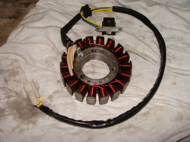
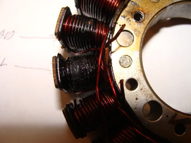
This is not a model engine stator (unless you ride a Harley) that went bad on me after 13,000 miles.
DSC00386.jpg

All the information I need for rewinding it is noted because this project may take a while to complete. I ordered a new Stator from the manufacturer through the dealer I purchased it from. Considering the quality of the made in China burned up stator I'm sure I'll be replacing it in about another 13,000 miles. I'll have a quality stator ready to go when that happens. A visual inspection shows a burned up coil and another in the process of burning up.
DSC00392.jpg

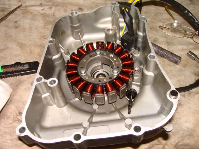
This is a 3 phase stator so when reading output voltage you must check across each of the 3 lines and note the voltage produced. In this case phase 1 reading was 30 volts, Phase 2 was 5 volts, and phase 3 was 21 volts. All the coils on phase 1 looked fine and had the correct voltage according to the manual. Phase 2 is obviously bad. The coil in the process of burning up was having an effect on the voltage output on phase 2.
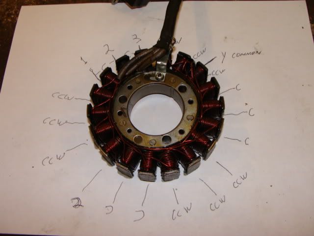
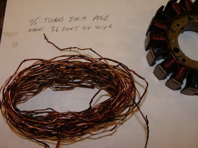
As I was removing the wire I noted how many turns of wire were wrapped on each pole which was 35 and after removing the wire measured it length which came out to 36 feet.
DSC00393.jpg

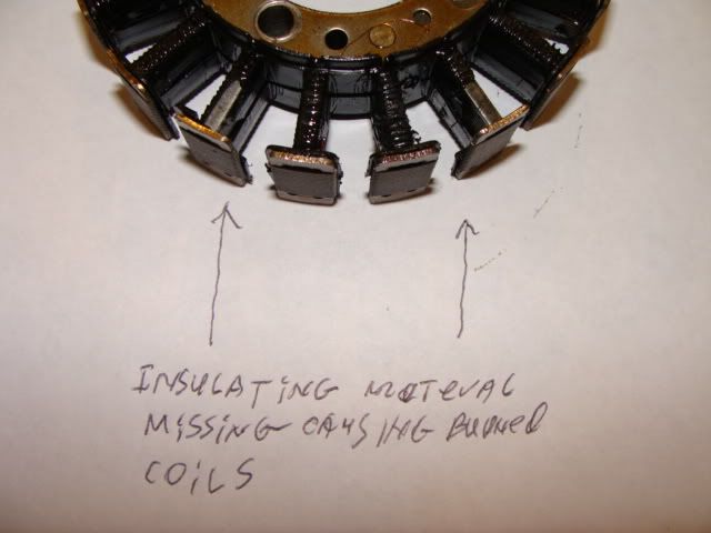
During the unwinding process I carefully watched for anything that would have caused the stator to burn up. I found it. The plastic material was missing causing the coils nearest the output wires to burn up. Don't ask me why the shorted coils did not burn up! I've rewound many motors and alternators over the years and most burn up coils at the output connections. This is the reason you never rewind a single burned up pole or attempt to partially rewind any motor or alternator.
DSC00397.jpg

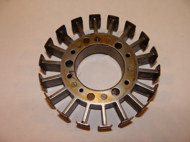
This is the stator core all cleaned up and ready for rewinding. I'll stop by the local motor rewind shop and purchase the necessary wire and insulting material to replace the cheap plastic crap they used. I've purchased stuff from them before. As long as it's something they would not do (and they would refuse to rewind this stator) they will sell the wire and insulating material necessary to do the job.
DSC00398.jpg
 
Interesting please keep posting! Looks like something that may come in handy at some time!
 
I am sure the vibration is not doing the insulation any good.
Some of the industrial transformers I see are potted with epoxy to make them more rugged and resistant to vibration.

Not sure if you could pot that coil or not.

 
Whilst the Chinese produce some good stuff - some of their cheaper winding wire enamels and quality control leave a lot to be desired.

If just one turn shorts it will generate almighty currents within the shorted loop and it will burn - obviously spreading to the next coil and so on to total failure.

I once bought a Chinese industrial sized radial arm drill - mechanically it looked really well made.

I asked the dealer - "why so cheap" - his anwer "all the electrics will burn out in a year" - he was right - so I rewound all the motors and replaced all the electrics - everthing ! - its been as good as gold since.

A case of spoiling the ship for half penny's worth of tar - a shame really.

I'm sure your rewind will be far better.

Ken
 
Hi, I've done a number of those windings in the past. Most of the failures are due to a regulator fault, so be careful when you install a new stator and measure the current output to confirm that's all ok. A shorted diode in the regulator can burn the stator in minutes.
 
Well certain Yamaha and Honda models from the 80's will burn too, but that has to do with the enamels on the wire being only rated to 120 degrees C on an aircooled engine back then - this will just about never happen with a wire with a modern 200+ degree C enamels.
 
The winding shop should have wire with much better insulation that was originally used. You might also look at getting some of the insulation paper they use also.

The problem I had with my gold wing many years ago was because of the connector failing due to corrosion, which then raised the voltage in that coil which then failed.
 
Noitoen said:
Hi, I've done a number of those windings in the past. Most of the failures are due to a regulator fault, so be careful when you install a new stator and measure the current output to confirm that's all ok. A shorted diode in the regulator can burn the stator in minutes.
The regulator is fine because I built it myself. I used proper rectifier diodes and voltage regulator chips. I had to replace a regulator on another Chinese motorbike a friend had. He gave me the old regulator so I broke into it. It used fail safe diodes which always fail open so you lose a phase and get reduced output without burning up the stator. This is what happened to his regulator. It was sealed in epoxy but to save money they only coated the back of the circuit board. For once I was happy with Chinese "quality". If it had been a Honda regulator it would have been completely filled with epoxy so I could never figure out how it worked. I was still unable to repair it but I was able to reverse engineer it and build my own heavy duty version of it. I put replaceable fuses in each of the three phase output lines in front of the diodes and used 3 LM350 voltage regulators, one for each phase. The output of all 3 LM350 chips are combined for a minimum of 9 amps output. This is more than enough as the stator is rated at 7 amps maximum.
 
The replacement stator arrived Saturday afternoon so I spent Sunday installing it.
It only took about 10 minutes to put the new stator in and bolt the cover back in place. My motorcycle with it's fully automatic CVT transmission looks like an oversized Scooter because they make them all that way for some reason. This means it's completely covered in body panels. It took me 6 hours to put them back on the frame. While I was waiting on my replacement stator I removed all the body panels and did some upgrades to it. I removed the EGR valve and machined a block off plate to replace the now removed exhaust flange and pipe. This greatly improved performance and it idles much better now. I also replaced all the vacuum lines as the exhaust gasses from the EGR was beginning to damage them. Thankfully the rubber intake manifold looked fine. I have an extra one ready to replace it as they spilt open due to exhaust gasses coming from that stupid EGR valve. Making the block off plate was a pain in the ass. The head and EGR exhaust flange was designed in an effort to prevent what I just did. It took me 2 hours to machine and hand file it to fit in the recessed pocket in the head. Most people would have given up and put it back the way it was and replace hoses and the intake manifold when required. I also replaced the Headlight bulbs. A new design is out that nearly doubles the light output while drawing the same current. They produce an extremely bright blueish light which really grabs attention which is important on motorcycles day and night. I had to modify the headlight wiring for them because they operate on AC current produced directly from the stator. Here are some pictures because we all like to see pictures!
DSC00400.jpg

This is the new stator. They provided a new ignition sensor because it shares the same rubber seal for the stator wires where they exit the engine. That saved some time.
DSC00401.jpg

Stator and sensor bolted in and ready for instillation on the engine. The quality of this stator is profoundly better than the burned up one I removed. Much care was taken by the person that wound it as can be seen. The turns of wire on the poles are perfect.
DSC00402.jpg

Whoever designed this engine must have been a mechanic and actually worked on motorcycles.
Typically you must remove the flywheel to get at the stator. On this engine the stator and sensor is bolted to the engine cover making replacement super easy and fast. Note the EGR block off plate middle right in the picture. The other half is recessed in a pocket in the head. The plate is inserted and then twists 10 degrees so the bolt holes will line up. The factory flange was obviously made on a CNC mill due to the contours cut in the head and flange. I did a lot of hand work to get my block off plate to fit and seal properly.
 

Latest posts

Back
Top