Method for fitting Aluminium fins into slots

Home Model Engine Machinist Forum

Help Support Home Model Engine Machinist Forum:

This site may earn a commission from merchant affiliate links, including eBay, Amazon, and others.

picclock

Well-Known Member
Joined
Dec 17, 2010
Messages
262
Reaction score
3
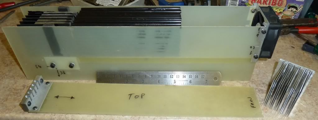
As part of a project I need to fit some 1mm thick aluminium fins into and aluminium block, around 10" long. The fins are spaced at 1mm apart. In order for the project to work well the fins need to have a good thermal contact with the block material. The slots are 4mm deep and the fins need good thermal contact with at least 1 side of the slot.

In an ideal world, you could cut the slots to exactly the correct width and the fin would be in intimate contact with the block, but the reality is that its very difficult to achieve even a decent push fit. Slitting saws of the same batch and thickness all produce differing results with regards to width.

I've investigated thermally conducting adhesives, but they are really not that good, especially with thin gaps. I've also looked at aluminium solder paste, but I don't think it would be possible to solder all the fins in one go, and once soldered, it would be impossible to remedy any problems as the other fins would be in the way.

So I'm trying to figure out an acceptable mechanical solutions.

#1 By making the slots slightly oversize, with an angular cut 2mm deep into one side of the slot, and hammering in pieces of steel shim to jam the fin against the opposite slot wall.

#2 I'm also considering deforming the fin by placing small indents at regular intervals along the fin length, thus using the straightening pressure of the slot to force the fin against the opposite wall. I may have to make up a device to set the spacing and depth of indent to get optimum repeatable results.

I have lots of fins to fix like this so I need a good repeatable solution.

Any other ideas or advice most welcome.

Best Regards

picclock

 
How about wedges or making the groove tapered (special cutter) - shallow angle - self holding - mill same angle on edges of fins and drive them in.
You can of course mill the tapered groove with a slitting saw in 2 or 3 passes.

2c

Ken

wedge.JPG
 
What is the height of the fins? Maybe it would just be easier to cut the fins right on the block with the appropriate slitting saw.
gbritnell
 
You could ask people that try to keep the latest aircooled Wrigth radial engines going.
Wrigth claimed that the cooling fins were replaceable in the field.

Kind regards and what is it for?

Niels
 
In theory at least I like the taper mounting idea. In practice, cutting, say, a 2 degree taper in a slot 1mm wide sounds danged difficult. If things were larger, you could use a tapered end mill but I doubt you could find one that small. You would also have to cut the matching taper on each fin. That you could probably do with a tapered end mill and a fixture to hold each fin as you cut it.

As suggested, you could cut the whole thing out of a solid block, but to do a block 10" long you really ought to have a horizontal milling machine.

You could stake each fin in place with a pin punch, except you don't have any really solid metal to work with; everything is so thin.

Have you considered the thermal compound used between computer CPUs and heatsinks? If you bent each fin into a slight arc, applied thermal compound, and sprung the curved fins into the slots, would that work?


You could try setting up the lathe as a horizontal milling machine
 
@KenI
If they were larger the wedge idea would be the one I'd go for, but the accuracy of trying to make a wedge that small over 10" would defeat me. Its similar to the first idea I stated but instead of a wedge shaped piece I was going to use some shim, and taper the hole for the top 2mm only, then drive the shim in with some force which would dig into the aluminium, hopefully producing a burr which would further lock the fin in place. The shim could be in short sections overcoming any local variation in slot/fin width.

The dual taper fin would be good but I don't think I could get the accuracy along the length - the taper would only be about 1/10th of a mm or 4 thou in old money. So whilst both of these are good for larger sections the size and scale of this project makes this not viable, at least for me with my current skill set.

@gbritnell
The height of the fins vary from around 1cm to 5.5cm. Not sure that I could get a 1mm saw that large.

@ niels
From my recollection of the Wright radial engines the cylinder and fins were manufactured as 1 replaceable part, so that if a fault occurred you could change the head, piston, and cylinder without even removing the engine from the aircraft. A really good design feature for a multi cylinder radial engine. Its for a special type of engine, if it works, woohoo1 I will post the info and pictures on here - if it fails my shame is my own :hDe:

@ mainer
I made up a test rig to check the different thermal conductivities of so called thermally conductive adhesives. As a reference to test against I used thermal heat sink compound. The results were, that far from being a reference, the heatsink compound produced much poorer results than even the worst resins. I think its because the resins and the heatsink compounds use similar metal pieces suspended in them, however because of the fluid nature the heatsink compound the carrier fluid must have a much lower thermal conductivity.

Bending the fins is really what I am doing with my second idea in the first post. A number of small deformations (just dents really) along the length will act as individual springs forcing the fin against the opposite groove wall, ensuring intimate contact.

Many thanks for your time and thoughts

Best Regards

picclock

finfix.png
 
a) can't You cut the slots 5/100 undersize and taper the bottom of the fins by sliding them at a shallow angle to fine sandpaper?
b) insert the fin in a slightly oversized slot, and push it in contact to one side with some pins?
c) knurl the bottom of the fin, to be inserted into a dead sized slot?

Marcello

ps.
Can You fit some silicon grease into the slots, to improve thermal conductivity?


I think I would try knurling the edge that goes in the slot. Glue the work down to a flat sheet of steel held on the table then mount a single wheel knurling wheel on the head of the mill and traverse the work under it. You could use the raise / fall on the table / head to adjust the depth of knurl. I think that would work. To give and interference fit.

 
Richard1 said:
I think I would try knurling the edge that goes in the slot. Glue the work down to a flat sheet of steel held on the table then mount a single wheel knurling wheel on the head of the mill and traverse the work under it. You could use the raise / fall on the table / head to adjust the depth of knurl. I think that would work. To give and interference fit.

or clamp the work among two steel flats, the larger one on the bottom and the second screwed to the first.
Marcello
 
@ Mzetati
Hi Marcello
Thanks very much for your ideas and input, I don't think I can use them as is but c) is a good starting point.
a)I've got no chance of tapering the fins evenly over a 10" length that way, also it would likely lead to point contact, not the area contact I'm looking for.
b) pins are just another variation of the shim in the side method on the picture I posted, bearing in mind the pin would be around 4-8 thou diameter that's tricky
c)knurling the fin is similar to the bump method in my picture. However it may lead to an easier way of doing the bumps.

I did some tests with heatsink compound (mainly silicon grease loaded with metal or oxide particles) and was surprised at how poor it was. I mounted a set of fins (3) in my tester and spaced them in the centre of the grooves using a layer of cellotape. These were then liberally coated with heatsink compound and inserted. I checked for direct contact with a multimeter, and apart from one which had a burr that I removed no electrical contact was present. My tester allows for 5 sets of fins, so the set next to it used cellotape on one side only to force direct mechanical contact against the side of the groove. The difference in conductivity was huge, and bearing in mind the narrowness of the gap involved (~1.5 thou) very surprising.

Will put up a picture of the tester I built if anyone's interested.

@ Richard1
That's a really good way of doing it, although I would probably clamp fin to table with mdf in between to allow some give. I think it would be better with a small bump say 1-2mm wide every 15mm or so, or a large bump of say 15mm followed by a gap of 15mm. I was thinking of just passing the metal through a couple of rollers like in an old mangle, but using the mill like that will allow much improved control of depth. Thought I could just turn up a piece of steel and mill a slot lengthways in one end for the insertion of a short piece of piano wire. The steel could then be wrapped with rubber to grip the surface over which it rolled. I think I have some rubber coated steel rods rescued from a defunct laser printer which may be modified to suit.

Many thanks for your help and ideas

Best Regards

picclock

 
picclock said:
a)I've got no chance of tapering the fins evenly over a 10" length that way, also it would likely lead to point contact, not the area contact I'm looking for.
b) pins are just another variation of the shim in the side method on the picture I posted, bearing in mind the pin would be around 4-8 thou diameter that's tricky
c)knurling the fin is similar to the bump method in my picture. However it may lead to an easier way of doing the bumps.

Will put up a picture of the tester I built if anyone's interested.

a) You only need the fin being narrower than the slot for, say, 1mm to ease insertion: then it will be forced into the slot by pressure, hammering, whatever... Gotta find a way to insert them without causing distortions.
b) there's a 1mm of space among the fins, and another mm on the fin itself: if You drilled rows of holes into the holder and then cut the slots intersecting them, You could use pins larger than 4thous. That would lead to one side contact only, tho.

That picture would be welcome.

Marcello


One more daft idea - have you considered soldering them in ?

One method would be to "Tin" the aluminium (special aluminium solder) then proceed with conventional solders.

With a bit of experinmentation with sizes you could probably get the tinning to act as the interference and then simply fuze them in place by heating ?

Regards,
Ken
 
@kenI

Yes, paragraph 3 first post.

Best Regards

picclock
 
There are high-temperature loctite formulations good to 450 f. or so, twice the boiling point of water. I've used this with success on engine heads. But I'm not sure about how well the loctite would transmit heat.
 
picclock said:
I did some tests with heatsink compound (mainly silicon grease loaded with metal or oxide particles) and was surprised at how poor it was. I mounted a set of fins (3) in my tester and spaced them in the centre of the grooves using a layer of cellotape. These were then liberally coated with heatsink compound and inserted. I checked for direct contact with a multimeter, and apart from one which had a burr that I removed no electrical contact was present. My tester allows for 5 sets of fins, so the set next to it used cellotape on one side only to force direct mechanical contact against the side of the groove. The difference in conductivity was huge, and bearing in mind the narrowness of the gap involved (~1.5 thou) very surprising.

That's expected, most heatsink compound is designed to conduct heat but not electricity. If it did then a whole bunch of electronics would break because heatsinks are often grounded.

I'd make the fins with a "finger" post at each end, loctite the finger into a deeper recess in the grove and use heatsink compound through the rest of the groove. Best of both worlds.
 
Hi Milotrain

The reason I checked for electrical conductivity was to ensure that no direct mechanical method of conduction existed. The plates on the tester are about 2" long and the gap distance very small so any crud like burrs could cause a direct conduction heat path and skew the results.

Heatsink compound is no match for direct mechanical conductivity.

@Marcello

Testertopandcarrier.jpg


Picture of the tester I made. Each carrier holds 5 sets of 3 test fins, one set of which is used for a reference. The carriers are heated by a resister powered from a car battery charger, around 150W, which also powers the fan. The block at the left end of the top has cut outs to allow accurate positioning of thermocouples to measure the amount of heat transferred to the air from each set of fins. The measurements are differential and made relative to the std direct conduction fin set. Takes about 25mins for the temperature to stabilise.

Other pictures at http://s917.photobucket.com/albums/ad19/picclock/Thermal Conductivity tester/

Best Regards

picclock


Probably stating the obvious - but have you considered bolting the entire block together from plates ?

Ken

Fins.jpg
 
@ KenI
Yes. If you bolt a stack together to some extent you make things worse. The number of junctions between the fins and the core increases, additionally you then have to thermally connect the assembled fins to the block. With fins in slots each fin has a direct connection to the block limited only by the joining method.

I need a minimum of 2mm direct contact from 1 side to get an adequate result. By putting shallow dimples or bumps in the fins this will provide adequate mechanical pressure to ensure this. The slots are 4mm deep, so by forcing the fin against the side this will give and average contact are well in excess of the minimum.

@ Swede
There are no high temperatures involved, perhaps a maximum of 50C.

Best Regards

picclock
 
Hi picclock
if you have access to a small furnace, You could try to heat shrink the 10" block onto the fins.
Use the block to make a sand mold the correct size,
stack the fins separated with wood slices the correct spacing, leaving a few mm overhang on each fin,
melt the 10" block and fill the sand mold.
As the casting cools it will shrink gripping the fins extremely tight.
The timber will turn to charcoal but will hold every thing in place until the casting sets.

Bez
 

Latest posts

Back
Top