Maryak 10

Home Model Engine Machinist Forum

Help Support Home Model Engine Machinist Forum:

This site may earn a commission from merchant affiliate links, including eBay, Amazon, and others.
Jack,

Just the stitch mop will do me fine, thanks very much.

Best Regards
Bob
 
Hi Guys - (essses),

New week so new piece - The Cylinder.

Took me quite a while to remove the aluminium from all over the shop - don't quite no how but most of it seemed to want to reside in my left boot which was a real pain in the...... foot. ::)

A lump of steel for the cylinder.

IMG_0162.jpg


Roughing down the OD.

IMG_0163.jpg


The cylinder after cutting the fins. (That was a load of fun, only broke 2 tools and each time was clean undies
smiley-scared001.gif
)

IMG_0164.jpg


The centre hollowed out ready for parting off and reversing into the 3 jaw.

IMG_0165.jpg


Bob's blood heat rule saw me stop and go home for a shower ;D
 
Great documentation as usual Bob. Will be interested in seeing how this cylinder finishes up,

Cheers
Phil
 
Thanks Phil for your encouragement, Yep it will be interesting to see the end result.


Steamer - Me SCARED
smiley-scared005.gif
??? ???

Best Regards
Bob
 
Looking GREAT Bob!

''(That was a load of fun, only broke 2 tools and each time was clean undies )"
I've snapped off lots of parting tools and blades in my days.
With no mention of a change of socks required as well, I'd say your doing fine! ;)

Rick

 
Thanks Rick,

It was also a good lesson on why we wear safety glasses
smiley-cool02.gif


Best Regards
Bob
 
Maryak said:
Thanks Rick,

It was also a good lesson on why we wear safety glasses
smiley-cool02.gif


Best Regards
Bob


You got that right!

Dave
 
Bob,

If the bore is not finished yet, put a small 60 chamfer on it and bring the tailstock up. Just enough to get a chamfer all the way around and no more.

The support will help with the grooving.

Dave
 
Thanks Dave,

Good idea :bow:

I actually did the grooving whilst the live centre was engaged and completed it before I began the bore.

Best Regards
Bob
 
thanks again for shareing Bob,I am learning a lot from your posts.

Regards . Ian :bow:
 
Hi Bob,

Sorry for the mix up there.....its hard to tell how much front rake on that parting tool?

Too much is not a good thing....can result in soiled socks....so to speak......

Dave
 
Seagar,

Thanks for your continued support on my second adventure. :bow:

Dave,

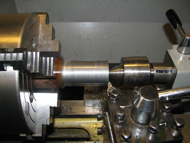
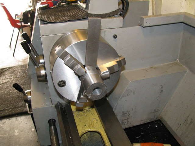
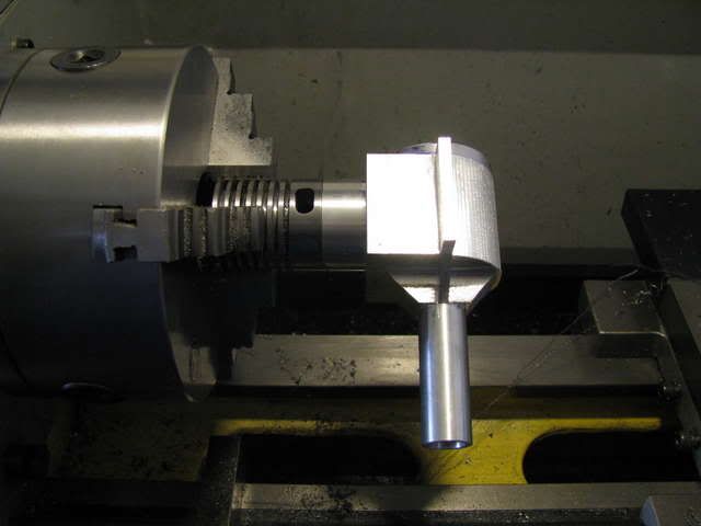
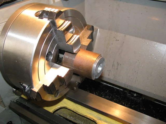
I guess it is hard to see the rake as only the rear of the parting tool is in shot, probably somewhere around what you can see, only the other way up. The tool in the tool holder is a finishing tool for the longitudinal. Thanks for your continued interest.

Best Regards
Bob
 
Much cooler today so spent a bit more time in the sweat box - hit +40C at 2:30 so called it quits.

Here's what went down today.

Setting up the cylinder in the 3 jaw - the parallel is positioned to measure the length more accurately.

IMG_0166.jpg


The bottom of the cylinder to length and the dia is the PCD of the transfer ports.

IMG_0167.jpg


A Gerry and the hat tricks poor mans angle plate for drilling the transfer ports. ::)

IMG_0168.jpg


IMG_0169.jpg


Drilling the transfer ports.

IMG_0170.jpg


Drilling the exhaust ports

IMG_0171.jpg


Milling the exhaust ports.

IMG_0172.jpg


And that's it from him today
xyzwave.gif


Bob looks real good

I really like your inginuity with the threaded rod to get the angle

i would not use it with a fly cutter, but punching small holes straight down ...

cool!

the whole thing is looking great Bob

i see adelaide is sweating too! keep the fluids up, dont work too hard,

and take care of you and yours , its a tad warm not to eh..

oh and rag wheel on the way

cheers

jack ..

 
Bernd & Jack,

Glad you liked my angle improvisation - cribbed the idea off my satellite dish where it was used to fine tune to the satellite.

Thanks for your support and encouragement. :bow:

Thanks for the rag wheel jack.

Got a little done today progress interuptus came with a sheet metal job on a wine tanks insulation.

First up I completed the exhaust ports.

IMG_0173.jpg


Back to the lathe a turned down the locating spigot for the cylinder crankcase interface.

IMG_0174.jpg


The crankcase mounted on the cylinder spigot.

IMG_0177.jpg


As an aside when moving chucks etc from one machine to another I find it's easier to get repeatability if things go back where they came from. Just a simple centre pop on the lathe and rotary table backplate matched to a similar centre pop on the chuck or face plate.

000_0005.jpg
 
The transfer passages on that engine are the two drilled holes parallel to the cylinder bore?

Coool......Most of the time I see that feature as some brazed on assembly.

Looking good Bob!

Dave
 
Started late finished early

The bit in between was mostly boring. ::)

Boring, (the cylinder).

IMG_0178.jpg


Together at last.

IMG_0179.jpg


IMG_0180.jpg


A lump for the drilling jig.

IMG_0181.jpg


Now for the weeks paper work
smiley-signs131.gif


steamer said:
The transfer passages on that engine are the two drilled holes parallel to the cylinder bore?

Coool......Most of the time I see that feature as some brazed on assembly.

Yes they are, there are 4 of them, another 2 on the side you can't see. They are drilled at a an angle to the bore so that if I've done it right they come out in the bore below the top of the exhaust ports.

It's called Oliver porting after the guy who invented it and removes all that nasty offset and transfer cover plate silver soldering from the equation.

Have a look at my offerings in the Plans Board topic "The Maryak 10" http://www.homemodelenginemachinist.com/index.php?topic=3629.0. That should give you a much better idea than my ramblings.

Thanks for your continued support and interest. :bow:

Some of your work holding techniques are great and I hope you don't mind if I borrow a couple for later on in this project.

Best Regards
Bob
 

Latest posts

Back
Top