Mamod Roadster convertion Mk.2 A 'Mamod Morgan 3 wheeler'.

Home Model Engine Machinist Forum

Help Support Home Model Engine Machinist Forum:

This site may earn a commission from merchant affiliate links, including eBay, Amazon, and others.
Hi,

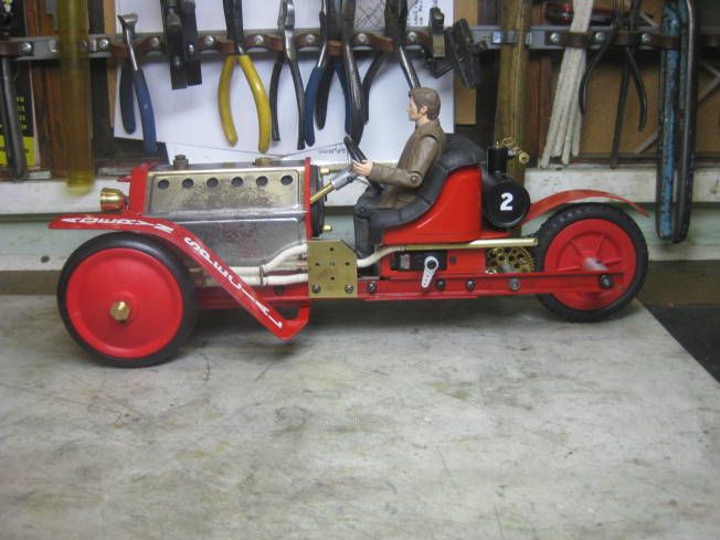
1. The steam pipes have had spacers fitted and been lagged, an extension piece has been fitted to the exhaust pipe.


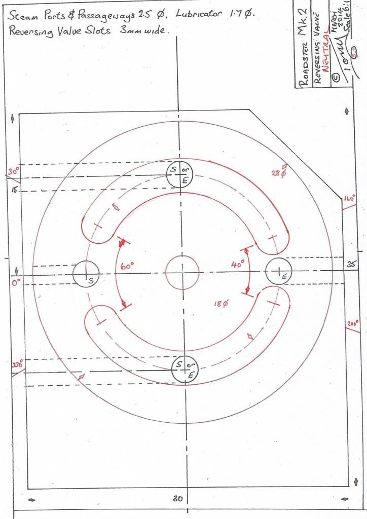
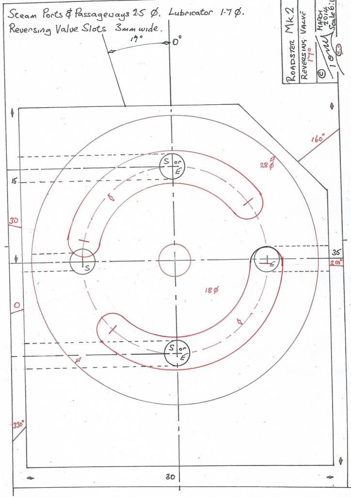
2. The type of reversing valve made and fitted works well as a throttle and can be radio controlled, which is helpful if a separate regulator isn't fitted and it also saves a servo. The poor drawings that follow I hope show how it works. Most servos have a 60 degree movement so the valve is designed to give a proportional throttle in forward and reverse within these limits. The idea is for the exhaust to be open before the steam inlet to reduce back pressure in the cylinder. The first drawing shows the valve in neutral.


3. The steam inlet is about to open and the exhaust is better than 50 percent open.


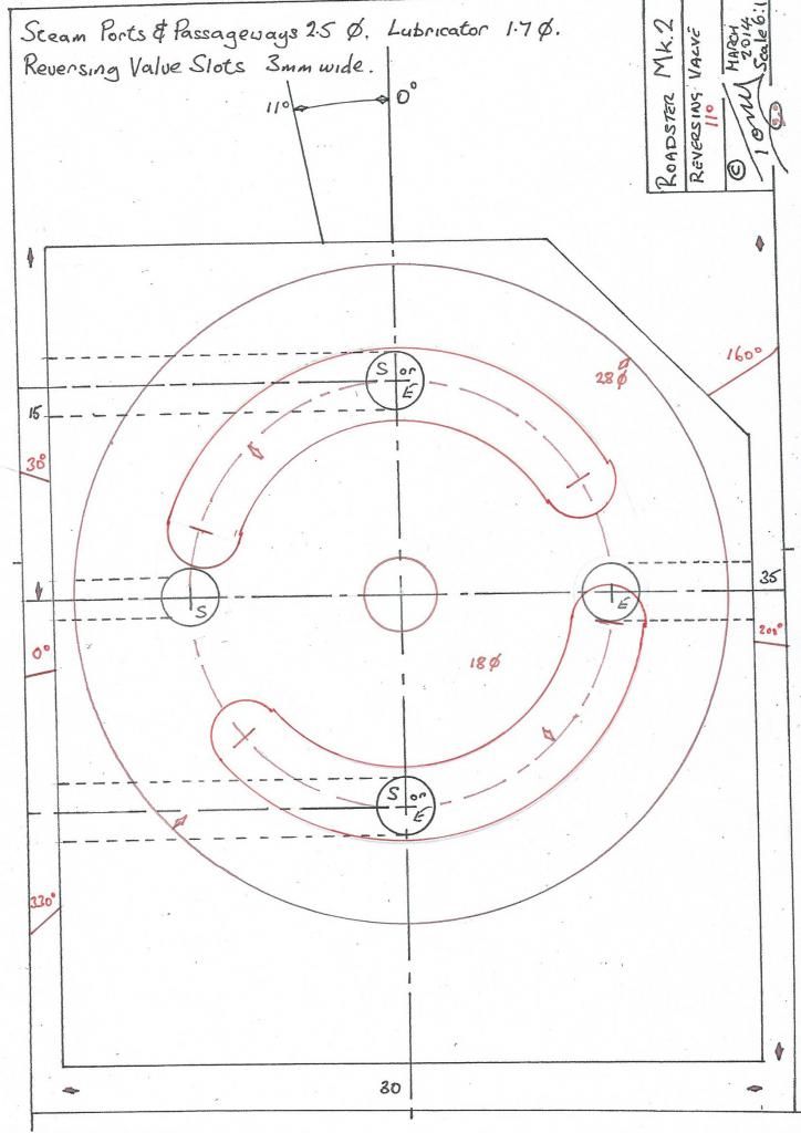
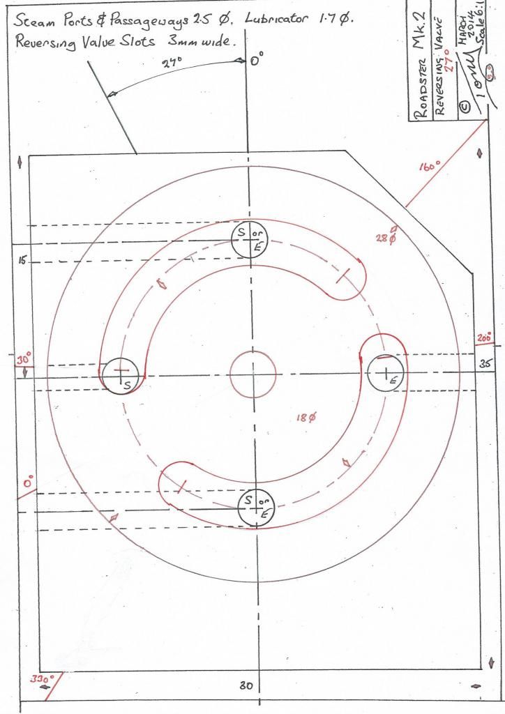
4. The exhaust valve is fully open and the inlet about 25 percent open.


5. Inlet fully open. By increasing the angular moment of the valve and shortening the length of the slots it is possible to arrange for the exhaust to be completely open before the inlet starts to open. I have used this type of reversing valve many times and it does seem to work a lot better than the valves where both the steam and exhaust open at the same rate.


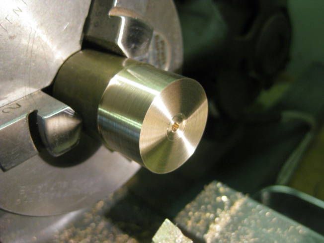
6. Machining the valve.


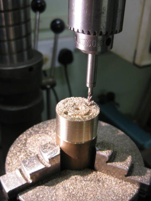
7. Milling the slots


8. Parting off the valve.


9. Machining the other side of the valve on a wax chuck fitted with a locating spigot.


10. Handle roughed out and test fitted.


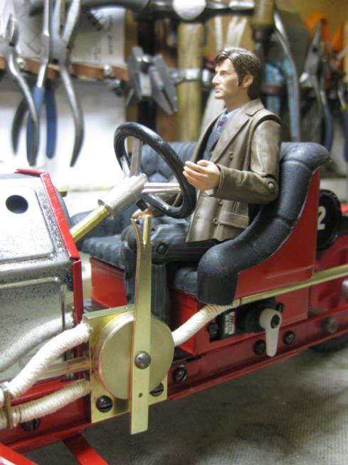
11. The model to date.


Regards Tony.
 
Hi,

A dead leg lubricator has been fitted which feeds into the reversing block which is the same system that worked well on the Mk.1 conversion.


Regards Tony.
 
Hi,

A start has been made on the ceramic burner for the Roadster.

1. Dry assembly of the components.


2. First section hard soldered.


3. Second section hard soldered.


4. Ceramic element supports and the gas/air pipe soldered in. It will look a lot better after pickling and painting. Honest!


Regards Tony.
 
Hi,

The ceramic burner for the Roadster is more or less finished.


1. After over night in the pickle.


2. A No.3 jet machined to fit the burner tube and held with Loctited to its feed pipe.


3. Burner painted with VHT paint with the ceramic element fitted and connected to a test gas tank. Note for VHT paint that requires heating to cure instead of putting it in an oven; just play a soft gas torch flame over it for a few minutes. Best done with good ventilation.


4. The burner ceramic lit but yet to be sealed into the burner using silicon sealant.


Regards Tony.
 
A few questions, if I may:

What gas are you burning?

How quiet is this ?

How do you source the ceramic for the burner? Are there alternatives?

thanks

f
 
Hi,

The ceramic burner for the Roadster is more or less finished.

3. Burner painted with VHT paint with the ceramic element fitted and connected to a test gas tank. Note for VHT paint that requires heating to cure instead of putting it in an oven; just play a soft gas torch flame over it for a few minutes. Best done with good ventilation.

Regards Tony.

That's a darn good idea!

Dave
The Emerald isle
 
Hi Charles,

What gas are you burning?

The burner will work with either Butane or a Butane/Propane mix which is 70/30 I think

How quiet is this ?

About the same as a gas ring on a cooker almost silent.

How do you source the ceramic for the burner? Are there alternatives?

Here in the UK it can be bought from model engineering supplies. The ceramic panels are used on portable gas heaters. There are two types a hard china like one and the one that you want which is soft and can easily be cut with a fine saw.

Regards Tony.
 
Hi,

1. A bit of a problem, when the gears were reduced in size to clear the engine mounting screws it moved the propeller shaft inwards so it fouled the newly made burner!


2. The burner has been moved a couple of mm sideways to give clearance.


3. The ceramic element sealed into the burner using a silicon sealant (bath sealant). Holes have been drilled through the high points of the element to increase gas flow if it is thought necessary to fit a larger jet at a later date.


Element not sealed.


4. VIDEO. Steam test to see how well the reversing valve sealed and whether the lubricator worked. A small seep on the reversing valve and the lubricator worked OK.


5. Boiler back on chassis and gas pipe connected.


6. VIDEO. Checking R/C control of steering and reversing/regulator valve.


7. Progress to date.


This leaves the engine left to make which won't happen for a least a couple of months as other projects, exhibitions and holidays have to be addressed first. Before I forget how I have decided to do it, the engine frame might be fitted to the front of the chassis.

Regards Tony.
 
Hi,

Definitely the end for a bit. The engine frame has been roughed out and fitted while I can remember how I was going to do it. A flywheel has also been made.

1. Flywheel partially balanced until the crank pin is fitted when it will be finally balanced.


2. The engine frame and flywheel fitted which is how it will remain for some time.


Regards Tony.
 
Hi,

In May 2013 I started this thread on converting a Mamod Roadster into a three wheel version that resembles I hope a Morgan 3 wheeler. This thread continued on and off until April 2014 when it stalled. The reason that it finished was because of the engine, the engine is based on an oscillating engine I designed years ago as a bit of a universal engine. The idea was that the same cylinders and port block could be used as either single acting or double acting ones and used in different configurations multi cylinder horizontal, vertical, flat, 'V' etc. To this end I had built many cylinders and port block blanks and when it came to the Mamod I had run out. I had intended to make another batch but other projects came along. Having recently finished a project it had been suggested by SWMBO that it would be a good idea to clear up some of the unfinished projects before starting on a new one, to this end four 16 mm scale wagons have been finished and I have re-started painting a pond yacht. While clearing part of the workshop I came across some part made cylinders and port blocks of the Universal engine, so its back to playing with the Mamod Morgan conversion.

At the end of play in 2014 the model looked like this.


To easy my way back into the construction yesterday I made and fitted an engine crash bar and painted the flywheel. The Mamod Morgan is along side a previously modified Mamod Roadster.


A quarter view of the Mamod Morgan.


I also managed to find the engine drawings of the cylinder and port blocks.


So to continue the port blocks will be drilled and fitted to the engine mount.

Regards Tony.
 
Hi,

I did some more work on the engine today, not a lot as I am still getting back into the engine's design and construction.

The tin of engine bits I found.


Two of the port blocks spotted then drilled.


The port blocks fitted to the engine frame and a shouldered bush has been fitted for the flywheel axle.


Front view of the engine frame with its port blocks fitted.


Regards Tony.
 
Hi,

Not a lot of progress has been made, still getting back into the project.

The ports have been spotted then drilled in the port block using an slightly under size drill.


Dimensions were checked and the ports size was increased so it was nearly the same as the distance between the ports. (bottom set of ports in the photograph).


As the two port blocks are different and have to be fitted the right way around they are being made separately. The right hand one was tackled first the steam having to travel though it to get to the other. The holes to be drilled in the port block six of which have to be plugged the remaining four will have steam pipes soldered in them.


Before starting on the second port block the relief for the cylinder was machined in the first one. This was done using a wax (shellac chuck) which is slightly different to the usual type as the face of it is away from the chuck that holds it. The reason for this is so that a gas torch can be played on the back of it while it is held in the lathe so the work piece can be centred. In the brazing hearth the work piece is stuck to the chuck in the usual way and allowed to cool until it wont move on the chuck and while it is still hot it is put in the chuck on the lathe. When fitted in the lathe the back of the chuck is heated until the shellac becomes mastic and the work piece is centre either as is shown using a tail stock centre or more accurately by using a piece of wood while the chuck revolves a bit like a potter centres his clay.


Fitted to the engine mount.


I might get the other port block done today.

Regards Tony.
 
Hi,

I haven't really done a lot more soldered the plugs in the port block and increased the diameter of the steam passageways to take the steam pipes.

The drill stops the plug being screwed in too far.


Just a small amount of solder.


Cleaned up.


Cleaning out and checking the passageways are still clear.


Shouldered steam passageway for steam pipe.


Reagrds Tony.
 
Tony:

I'm a little confused, why did you turn those areas on the RH block? At first I was thinking that, assuming both the LH and RH blocks are the same thickness, those areas would allow you use identical cylinders and the reduced thickness would offset the connecting rods. But it looks like the faces of both blocks are still on the same plane. What am I missing?

Don
 
Hi Don,

I'm a little confused, why did you turn those areas on the RH block? At first I was thinking that, assuming both the LH and RH blocks are the same thickness, those areas would allow you use identical cylinders and the reduced thickness would offset the connecting rods. But it looks like the faces of both blocks are still on the same plane. What am I missing?

Both the port blocks are the same thickness, the recesses cut on the port face is so the cylinder seals better to the port block and also to reduce friction between them.

I haven't decided yet the design of big end I will use, the Mamod Roadster I altered used one higher cylinder to get the off-set.


There are other options to having different thickness port blocks or higher cylinders, this looks well but time consuming to make.


This is simple to make and works well.


It is unlikely that I will use a higher cylinder but I might put a packing piece behind one of the port blocks and crank the steam pipes to get an off-set, if I do this I might use this type of big end.


Time will tell which system will be used. I have been side tracked to another project for a couple of days.

Regards Tony.
 
Hi,

The second port block has been drilled and plugged and the steam pipes cut and bent.


The pipes were soldered in place and water in a syringe was used to check the passageways were still clear.


The steam pipes to the reverse/regulator were cut and soldered in place and again water was used to check everything was still clear of obstructions.


The steam pipes were bent and attached to the pipes from the reverse/regulator valve using silicon tube.


Test assembly.


The engine plate has been painted and the steam pipes will be lagged after checking for leaks using steam.


I will make a start on the cylinders next week all being well.

Regards Tony.
 

Latest posts

Back
Top