You are using an out of date browser. It may not display this or other websites correctly.
You should upgrade or use an alternative browser.
You should upgrade or use an alternative browser.
Making a tapered D bit
- Thread starter Brian Rupnow
- Start date

Help Support Home Model Engine Machinist Forum:
This site may earn a commission from merchant affiliate
links, including eBay, Amazon, and others.
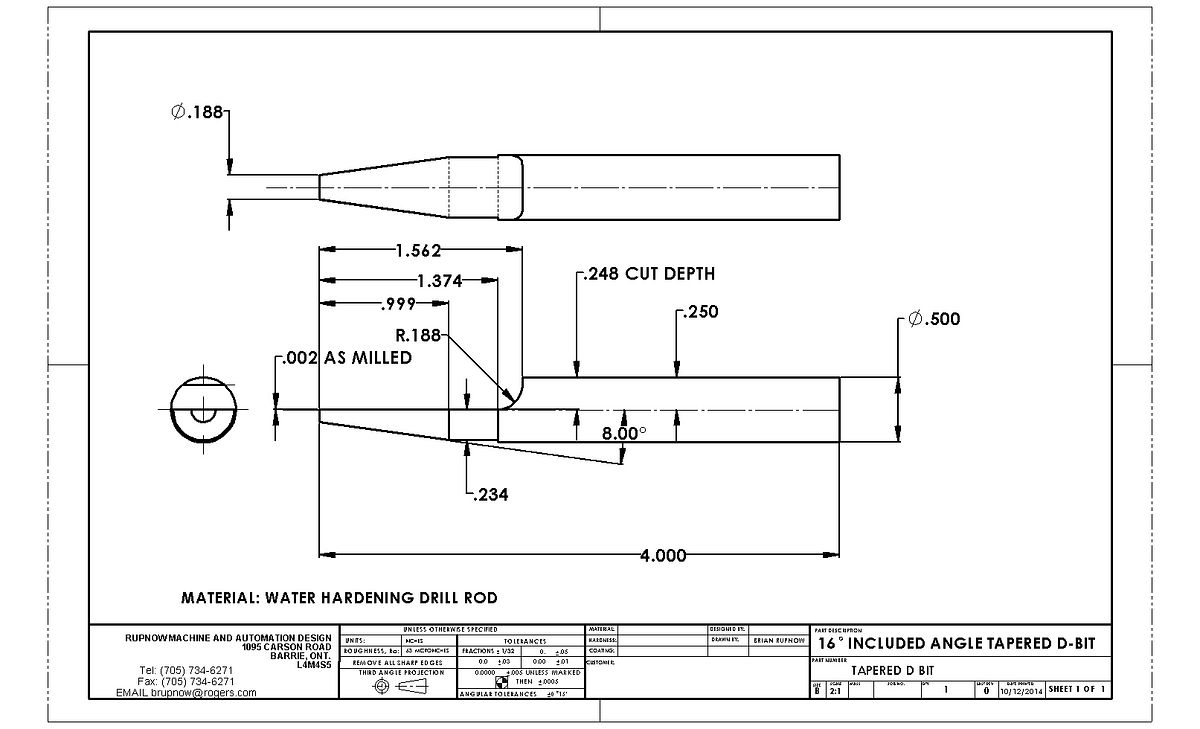
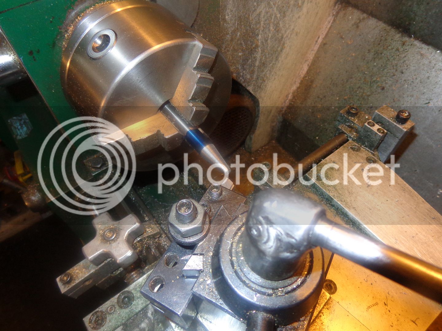
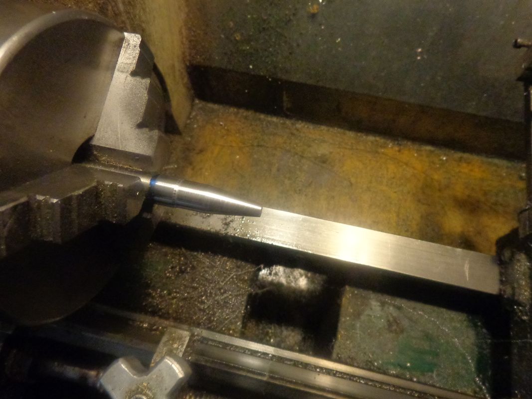
Now it doesn't show up very good in this picture, but after cutting the taper, I turned a 3/8" length of shaft down to 7/16" diameter right adjacent to the taper. Why did I do that?--Because I don't absolutely trust the vernier on the mill quill downfeed, and I wanted to be able to have a surface I could set the micrometer against to measure how close my cut was getting to the centerline when I got set up in the milling machine. I couldn't think of a good way to do that without having this small turned down area.

So, here we are in the milling machine, milled down to .002" shy of the centerline. I used a 7/16" diameter endmill and cut with the end of the mill down to the depth I needed to go. Then I used a 3/8" ball nosed end mill to put the radius in the heel of the cut. I dressed the newly milled flat area with a medium grit flat diamond file. (one of a set of 4 cheapies that I bought from BusyBee Tools .


After heating the new tool to an orange/red with my acetylene torch and dunking it into a can of water, I dressed the flat side with a few more stroked of the diamond file (I'm not really sure it was necessary, but I did it anyways). Then I set up a scrap piece of aluminum in the lathe and drilled a 0.195" hole in the end of it. That is the bore through the carburetors I want to build.
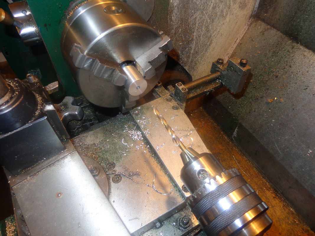

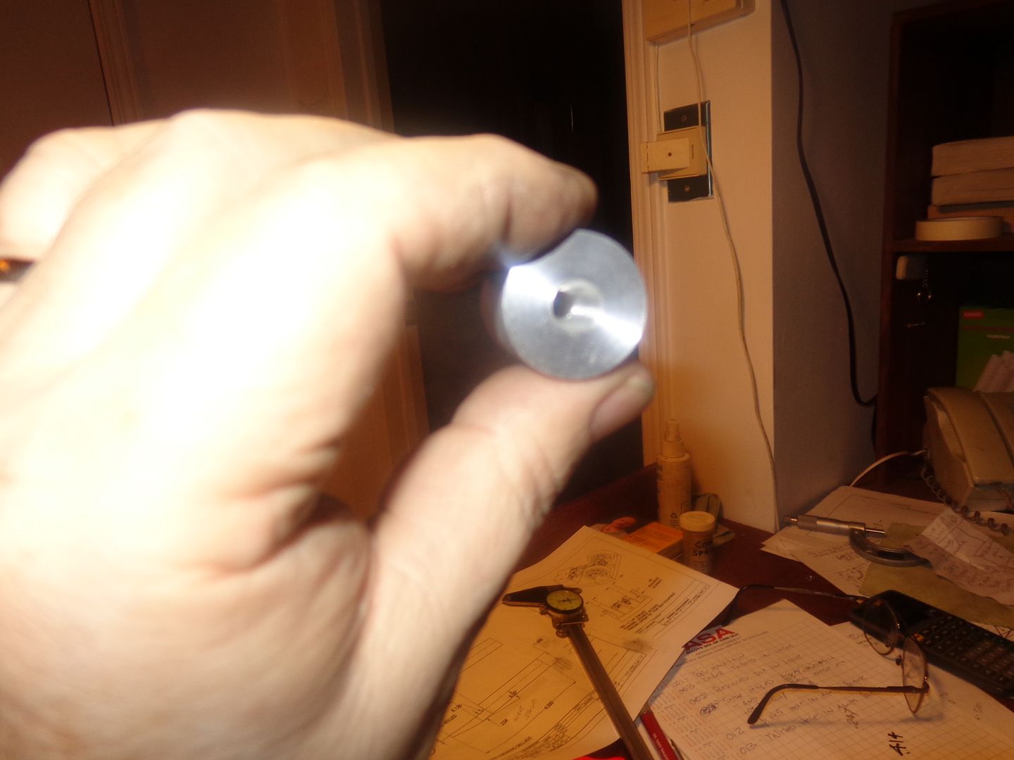
The new D-bit works very well!!! It cuts smoothly and leaves a nice finish on the tapered hole it cuts in the aluminum. I did not relieve the non cutting side of the new D bit--I left it full size, reasoning that it would prevent the D bit from wanting to be pushed away from the side that was doing the cutting and possibly break the bit.
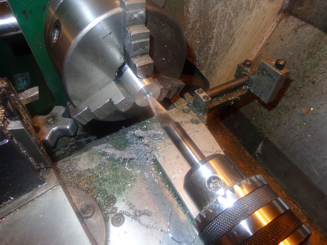

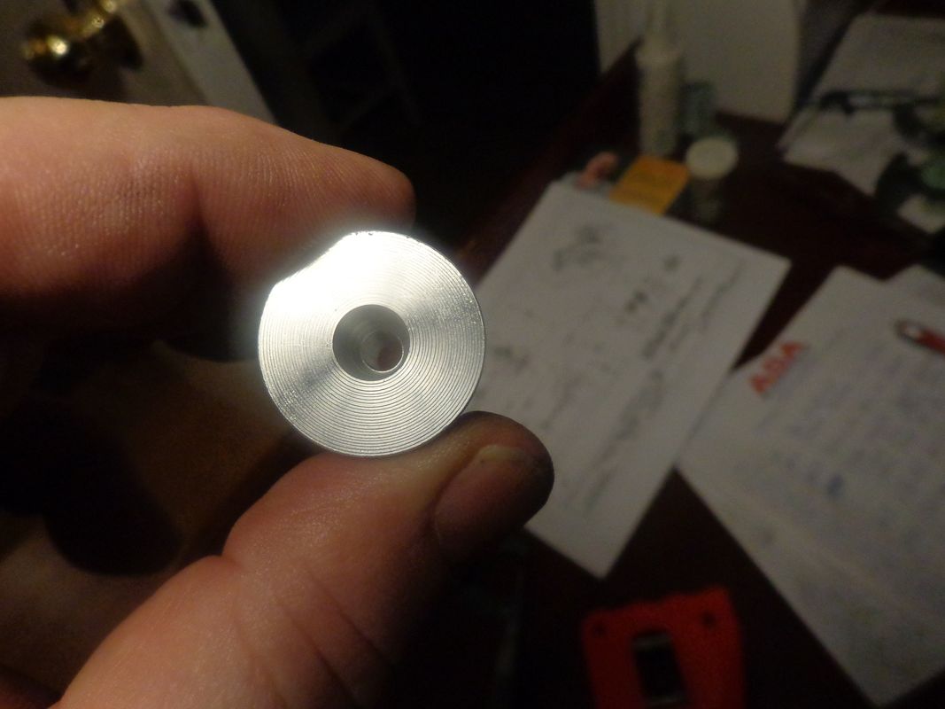
So---The making of the D bit was successful, and worked great. I am not certain, but I THINK I have to grind an angle on the very nose of the taper. Now we get to the sad part of the story. Although the operation was a success, the patient died!!! The protractor on my compound rest is one of those "By Guess or by God" kind of things. It is not engraved very well, and difficult to see. I estimated where 8 degrees would be, and used my cad program to determine that if the taper extended back .999" from the end of the material, it would leave me with a .188" diameter at the very tip, which would fit nicely into a pre-bored 0.195" hole. Damn Damn Damn--I didn't check that before I hardened everything. The small end of the taper turned out to be .215" diameter, and it leaves a shoulder at the end of the tapered hole--Exactly what I wanted to avoid!!! I have one trick left. I have made up an aluminum bracket which clamps in my toolpost to hold my heavy duty pneumatic die grinder. I may put an abrasive cut-off wheel in it and try to turn the taper down a bit more until the small end reaches the diameter I want. Fortunately I haven't changed the angle setting on my compound rest. At any rate, it has been a great learning experience.---Brian

- Joined
- Dec 12, 2012
- Messages
- 2,220
- Reaction score
- 1,285
They are cheap and quick to make,why not make another.You will probably make many more.Set up the lathe and cut a piece of mild steel until you get it right.Barry
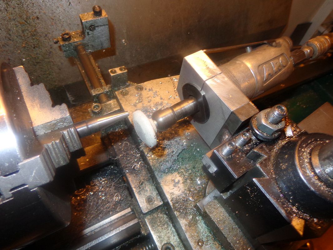
WELL!!! That went amazingly well!! I have a whole flock of small, unidentified grinding wheels mounted on 1/4" shanks that I have had, well, forever. I mounted my pneumatic grinder in a home made aluminum clamp and mounted it in my lathe toolpost, and with the lathe turning at 970 RPM I took multiple cuts .001" deep until the small end of the taper measured 0.188" diameter just as I wanted. The angle of the taper is not terribly important. It probably isn't exactly 16 degrees included angle, but it is certainly close enough for a carburetor air horn. Not wanting to start crowing about it too early (in case my "external grinding" had somehow rendered the tool inoperable), I again dressed the flat side a bit with a fine flat diamond file, then flipped my "test piece" with the .195" hole through it over and proceeded to put in a new taper. The nose of the tool fits INTO the hole now, cuts a lovely taper, and doesn't leave any "register" at the bottom of the taper.---Hooray for my side!!!


Slightly (.002") less than half the material diameter.So what is the rule of thumb on the mill cut? Slightly more than half the diameter or slightly less than half the diameter?
- Joined
- Oct 1, 2010
- Messages
- 1,341
- Reaction score
- 393
What Bazmak said.
When I tried this over a year ago I made about four variations of the tool I wanted to end up with from the beginning of the process, then selected the "best" for making the part. In a "Real World" situation, I would probably be fired for inefficiency for doing that, but I made an early decision that I would rather be orderly making several tries from the beginning instead of doing the whole thing over again and again and spending more time overall doing so.
Making one of these doesn't take a whole lot of time so extra work doesn't leave one so frustrated as spending a whole day on a part that gets filed under "small scrap pieces of stock."
--ShopShoe
- Joined
- Oct 1, 2010
- Messages
- 1,341
- Reaction score
- 393
Brian,
I see you made another post while I was typing.
Congratulations. I'm glad this worked out.
Can't live in my shop without my air die grinder and the little stones and also the diamond files.
--ShopShoe
I see you made another post while I was typing.
Congratulations. I'm glad this worked out.
Can't live in my shop without my air die grinder and the little stones and also the diamond files.
--ShopShoe
- Joined
- Sep 2, 2011
- Messages
- 1,342
- Reaction score
- 360
Brian, when I made my taper bit, I used angle blocks to set my compound to the face of the chuck, seems to have hit right on for me. don't know if that trick would work for you though.
Slightly (.002") less than half the material diameter.
Brian. I'd be interested to know how it cuts because I have been told to keep the material to + .002" admittedly for parallel D bits !
Dave
The Emerald Isle
I am probably teaching grandma to suck eggs, but just in case: hardening and not tempering leaves the tool very brittle and prone to chipping or breaking. You have managed to get away with it this time probably because you are working in ally. I try to temper tools like this until I can detect the slightest colour change on the honed cutting surface. It makes them a lit tougher without sacrificing hardness.
goldstar31
Well-Known Member
I hope that I have not going to wander off course or steal Brian's interesting post but ?????
Silver steel or whatever it is called is nothing more than annealed very ordinary tool steel and as such is capable of being machined with ordinary tools and then hardened to ANY hardness. Somewhat rudely, that is what it was and- ever more shall be so. It will harden with water, oil or as I remarked - stuck into an old potato. Looking back a few years, it was what EVERY model engineer used as his ONLY method of removing metal.
It was how EVERY model engine was made. It was how EVERY fullsize locomotive was made and earlier still how every cathedral was made. A hammer, a chisel.
Is there something that has changed?
As far as Brian is concerned, he has gone down a traditional road- and succeded. My only criticism is that he used Oxy/Acetylene as the heat source. To me, it is a bit 'iffy' as he was probably adding carbon. Nevertheless, I would mention that other model engineers, clock and watchmakers have case hardened silver steel rather than over temper it.
Would somebody explain or comment, please?
Norman
He was asking about the mill cut depth. My answer was that you stop cutting .002" from the centerline. we are both saying the same thing. You do NOT cut material away below the center.---BrianBrian. I'd be interested to know how it cuts because I have been told to keep the material to + .002" admittedly for parallel D bits !
Dave
The Emerald Isle
goldstar31
Well-Known Member
He was asking about the mill cut depth. My answer was that you stop cutting .002" from the centerline. we are both saying the same thing. You do NOT cut material away below the center.---Brian
I don't think anyone would be happy with 'negative' rake:wall:
Similar threads
- Replies
- 28
- Views
- 4K
- Replies
- 9
- Views
- 1K
- Replies
- 61
- Views
- 7K


