Making a Backplate for a Collet Chuck

Home Model Engine Machinist Forum

Help Support Home Model Engine Machinist Forum:

This site may earn a commission from merchant affiliate links, including eBay, Amazon, and others.

BobWarfield

Well-Known Member
Joined
Dec 27, 2007
Messages
1,151
Reaction score
1
It's not quite done yet, but I thought I'd get started posting since Divided He ad is trying to do something similar. I won't post everything here, it would be two long. The gory detail can be had on my web site here:

http://www.cnccookbook.com/CCColletChuck.htm

What follows are some highlights.

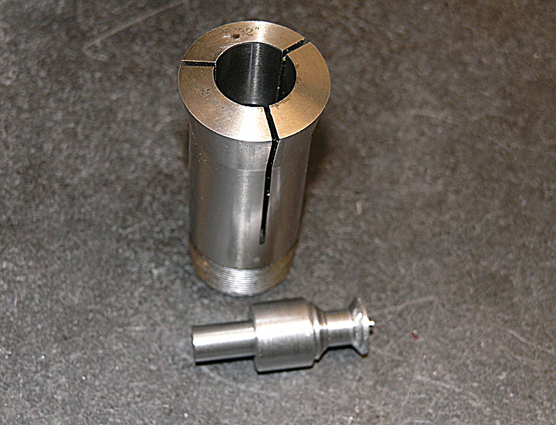
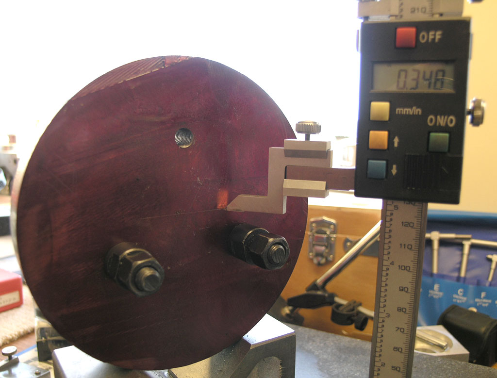
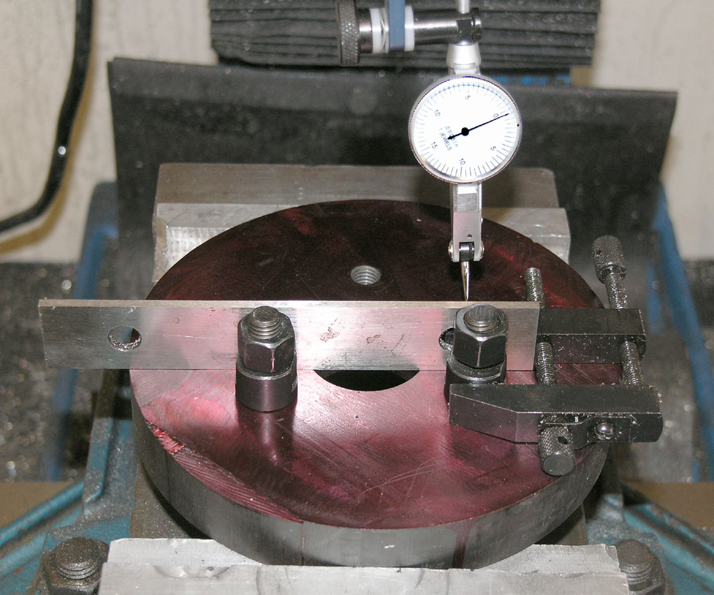
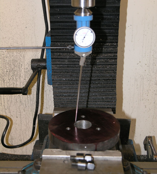
Since it's a collet chuck, I wanted to take extra care around accuracy. 5C collets can be really slick and accurate. We'll see how it turns out.

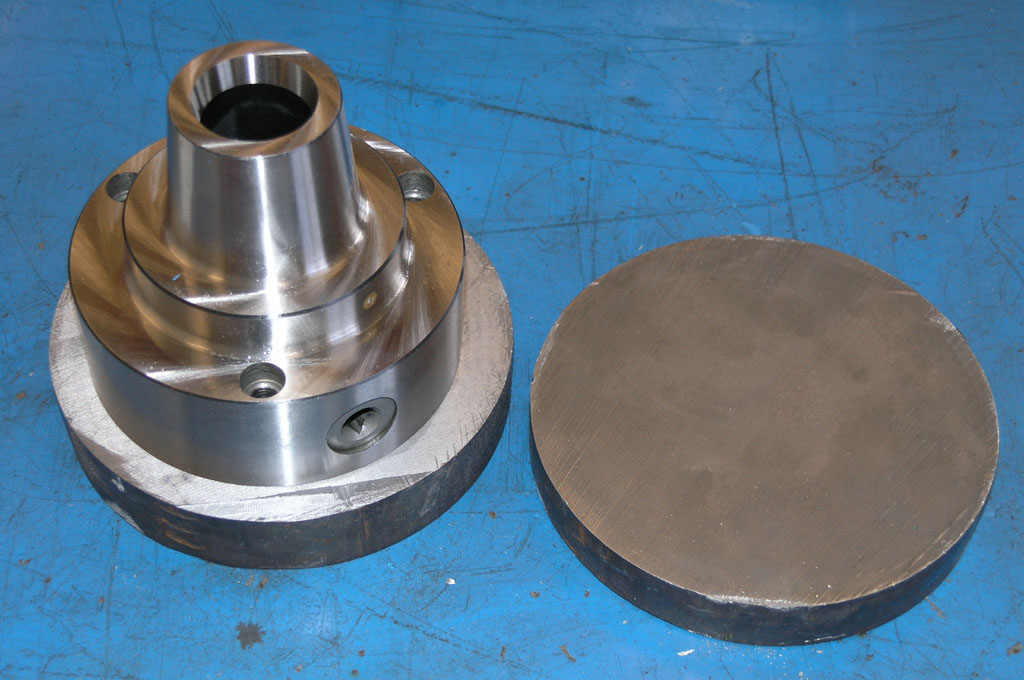
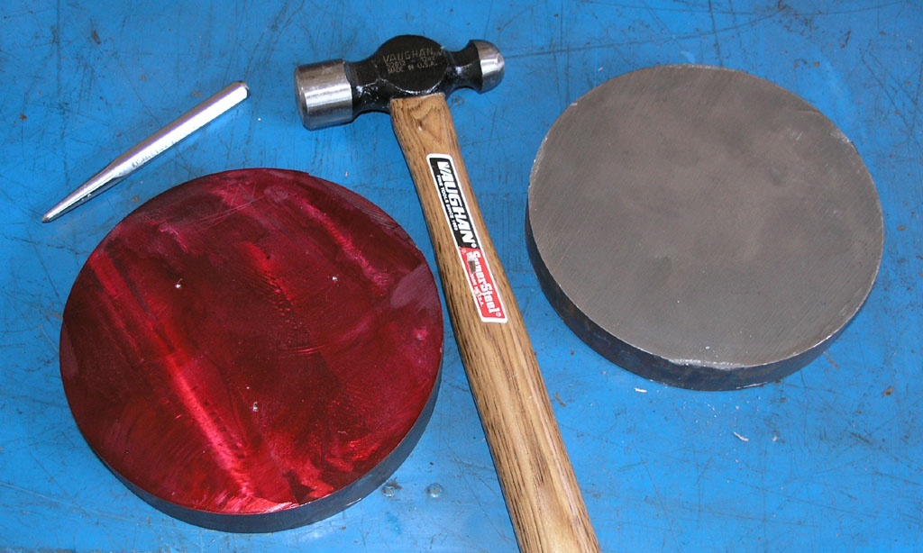
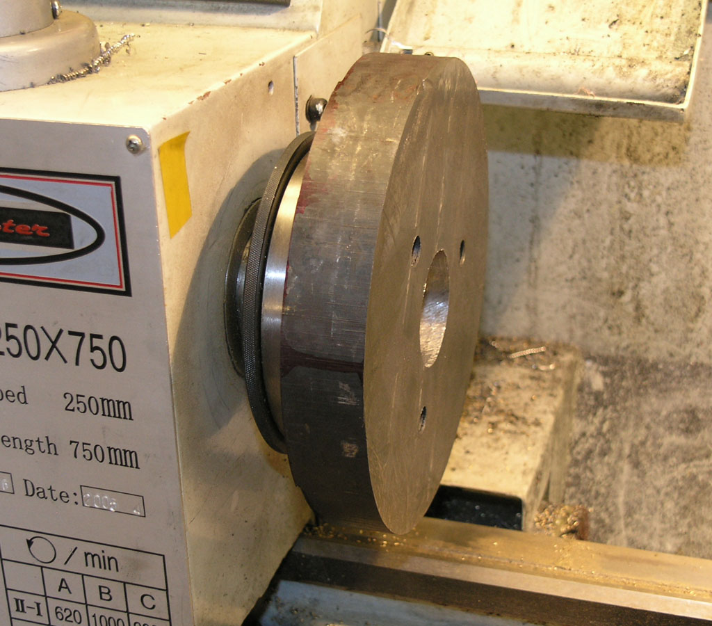
We start with a lump of sawn cast iron and the chuck:

P1010391.JPG


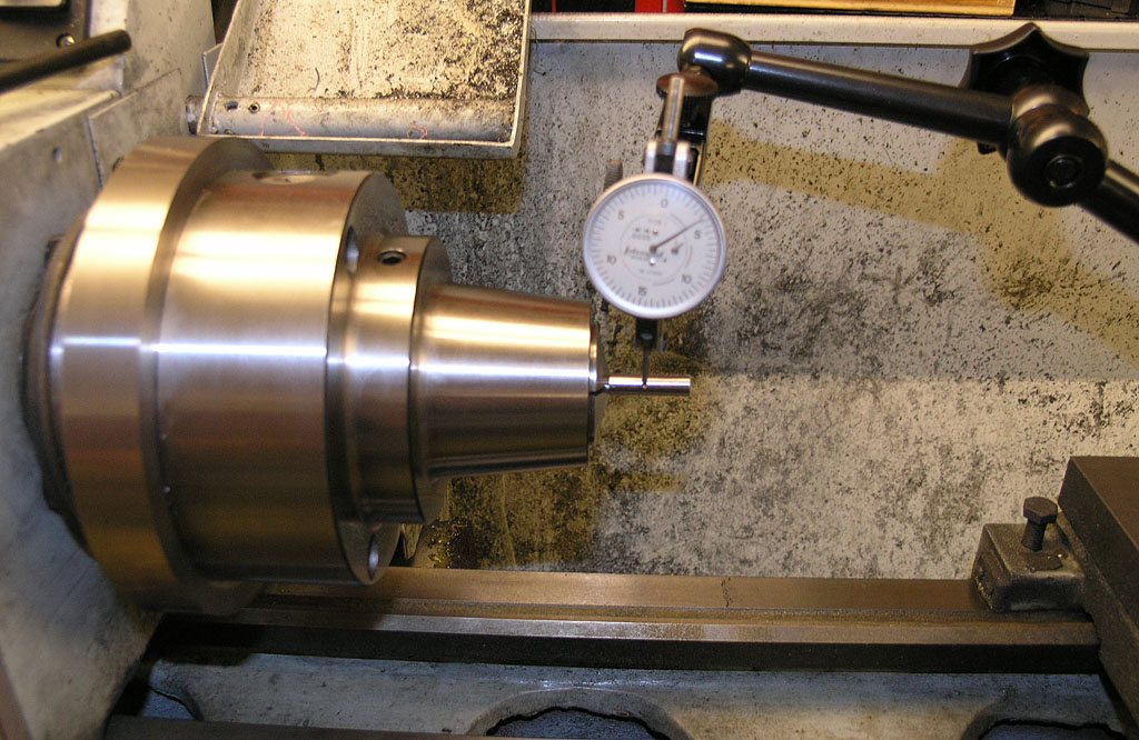
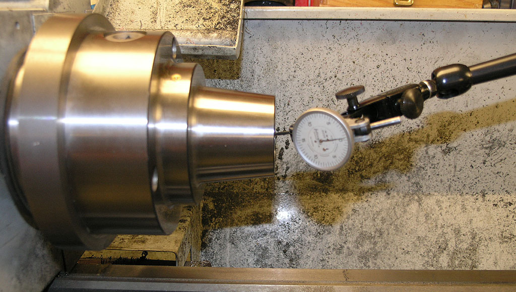
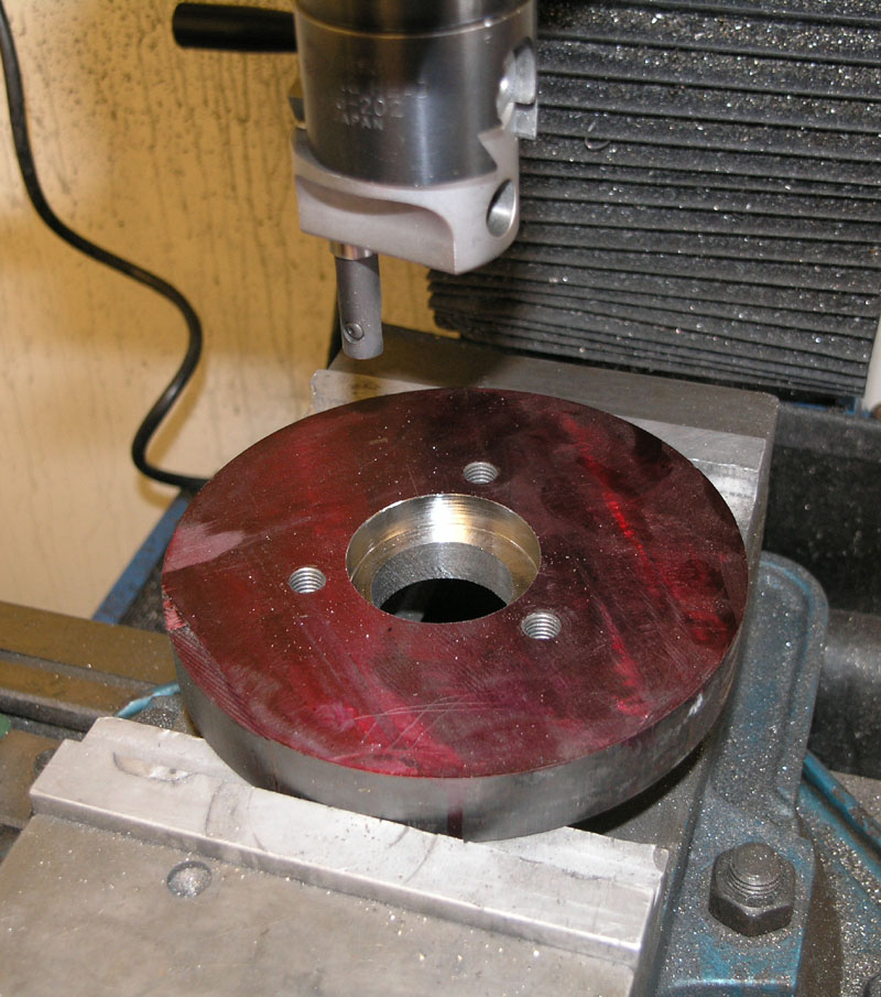
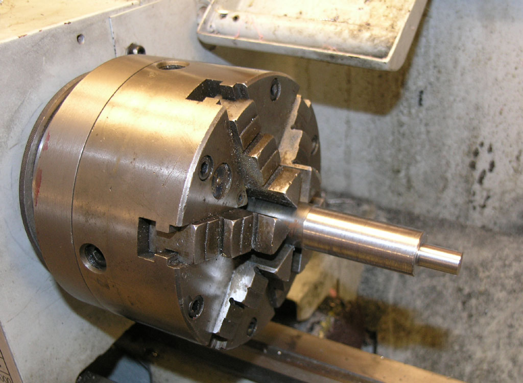
One of the great difficulties is holding a big workpiece like that in a small lathe. Many have followed Steve Bedair's method of using a bolt as an arbor. I tried that on my first backplate and it chattered and misbehaved like heck, so I resolved to make use of my mill to enable me to machine a passable but (I expected) not nearly accurate enough mounting to enable it to be held securely for more precise machining on the lathe itself.

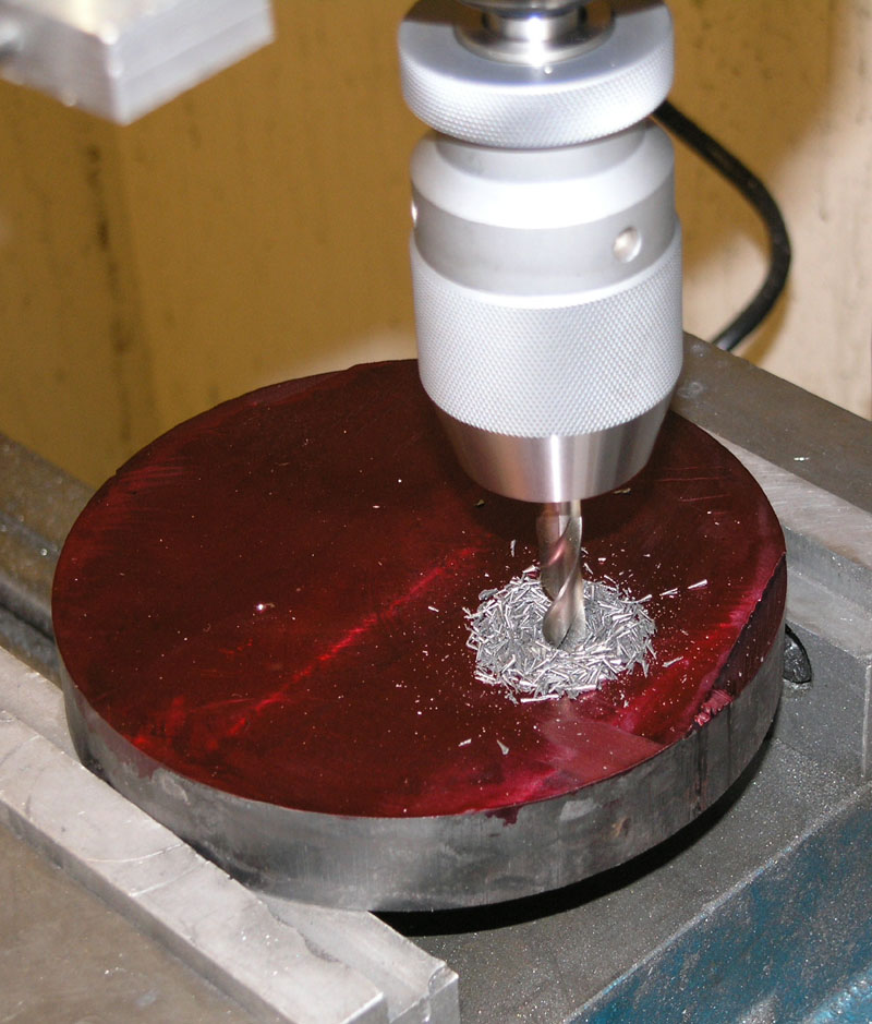
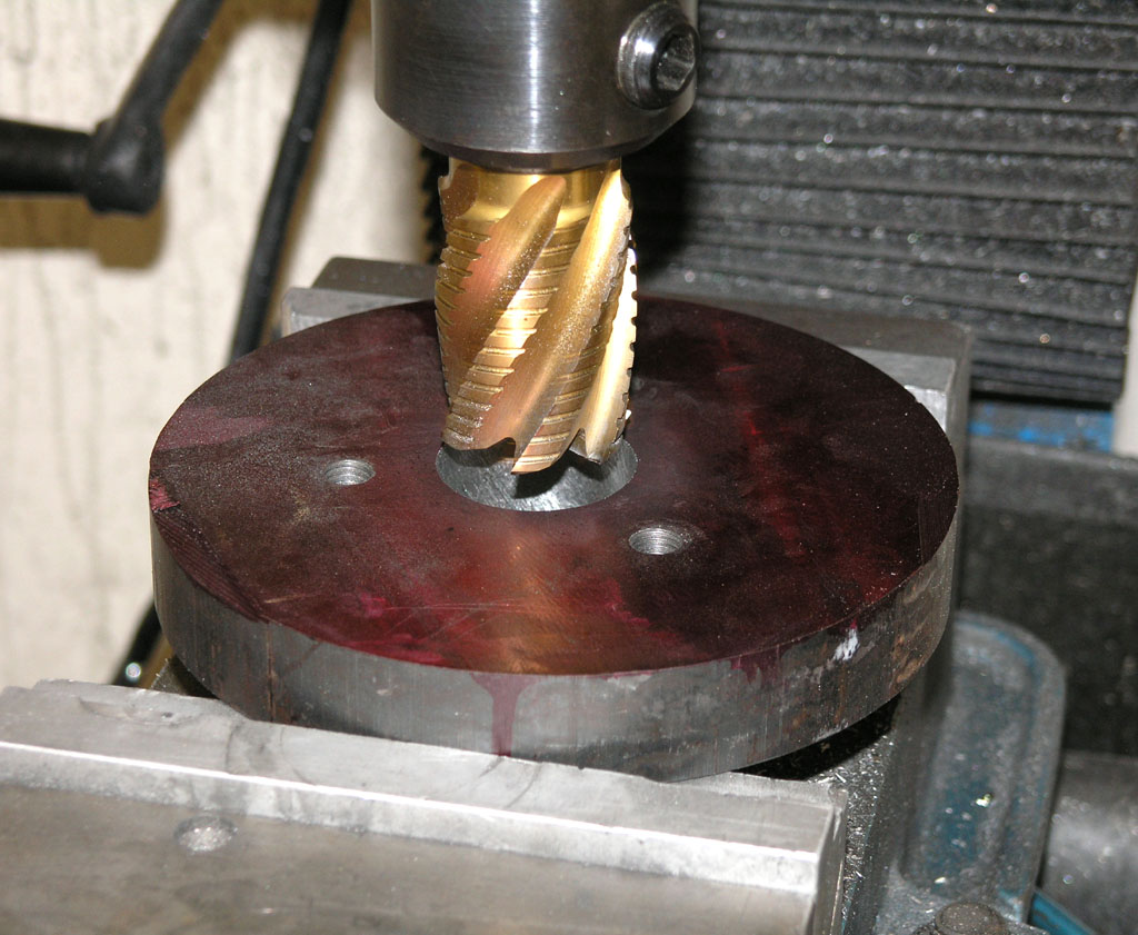
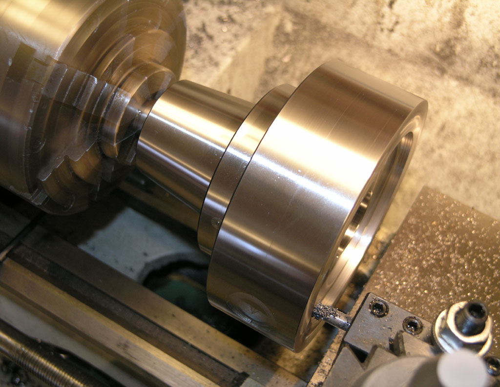
Job 1 is therefore to face the cast iron on both sides with my indexable face mill:

P1010411.JPG


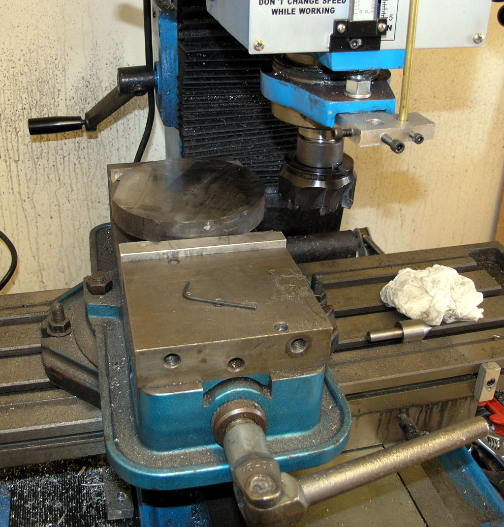
This iron was a little tougher to machine than other cast iron I've dealt with. Not sure why, but all's well that ends well.

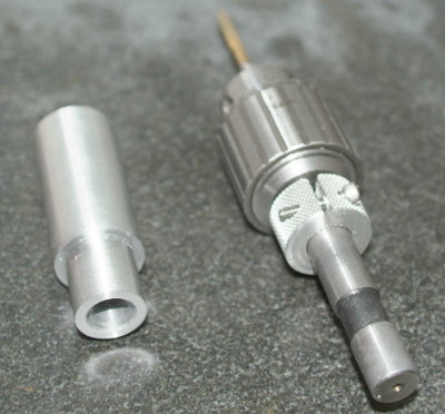
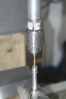
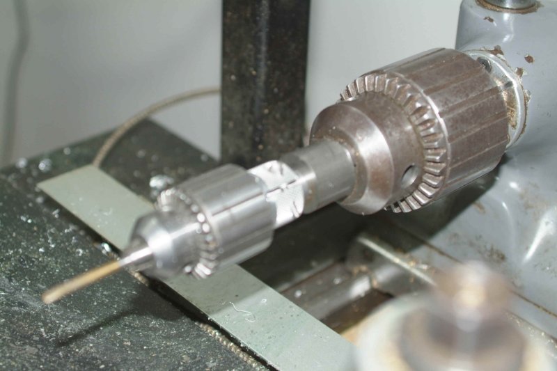
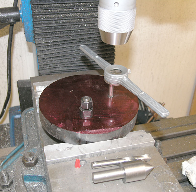
Next, I made a set of M10 transfer screws (process described elsewhere here and on my web site):

P1010410.JPG


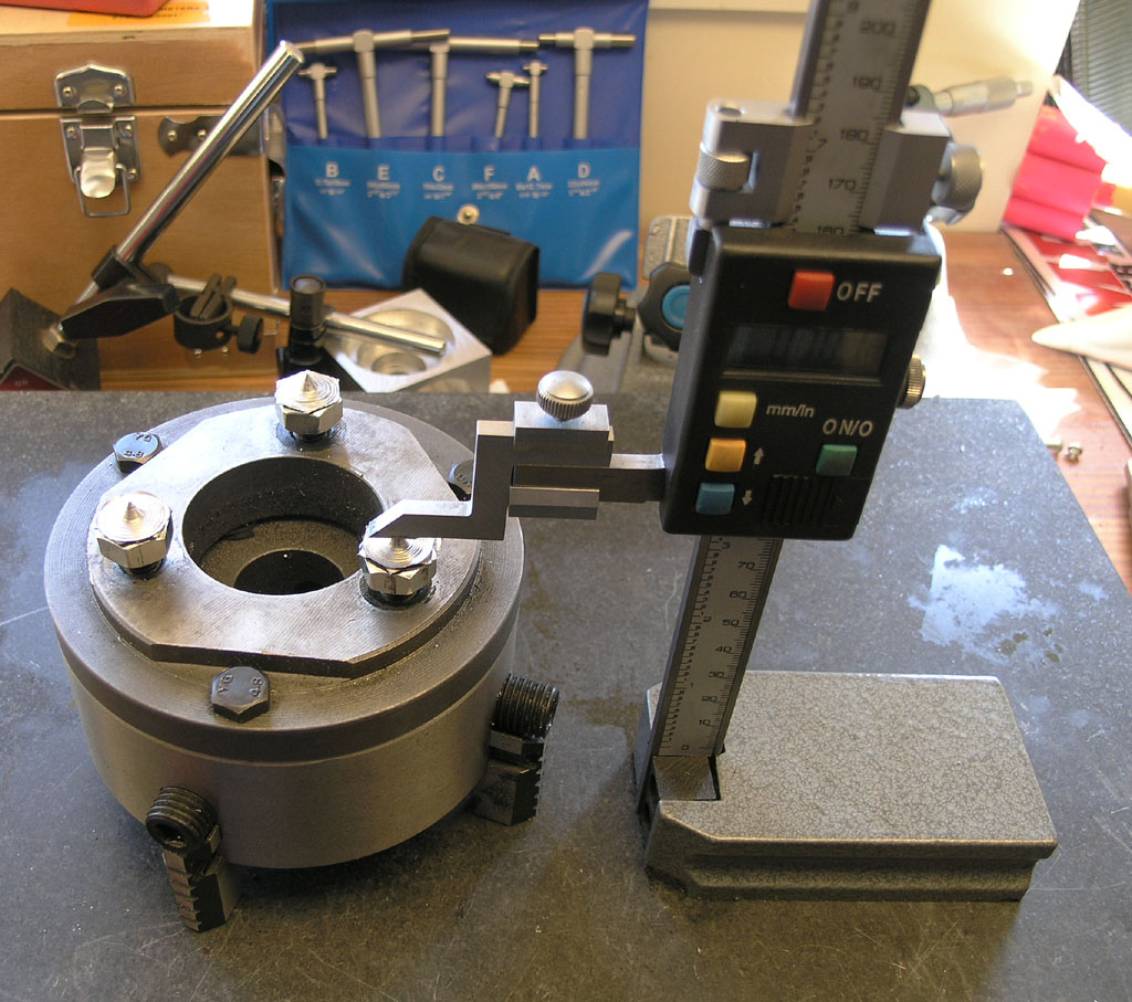
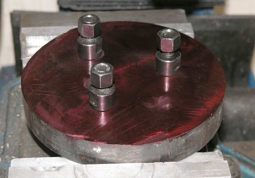
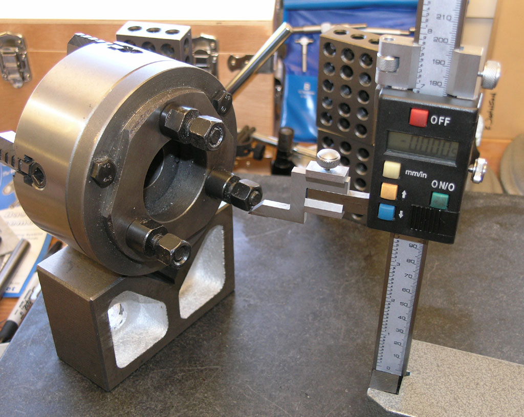
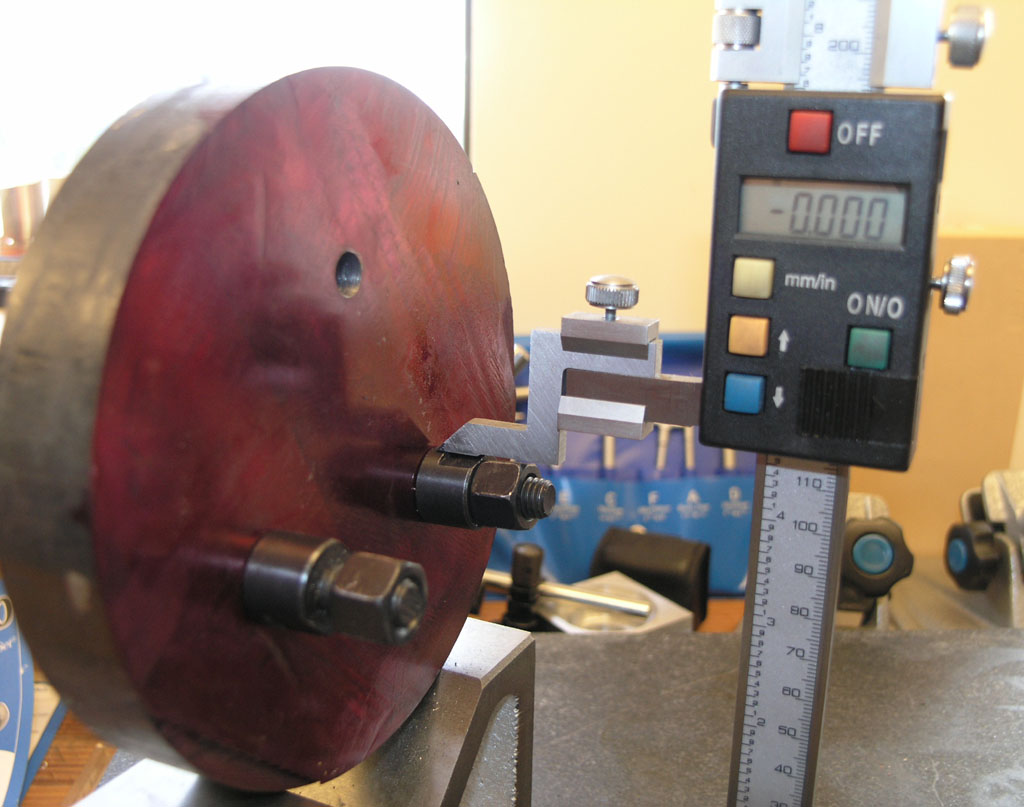
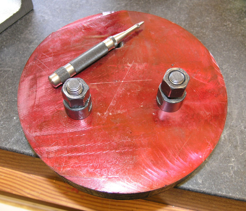
What goes in those 3 holes is sort of a faux cam lock as I call it. It's a set of barrels with nuts that are tightened. I quite like the system as I don't have to worry about the drawbacks of a threaded spindle and it is very rigid and accurate.

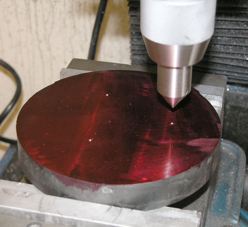
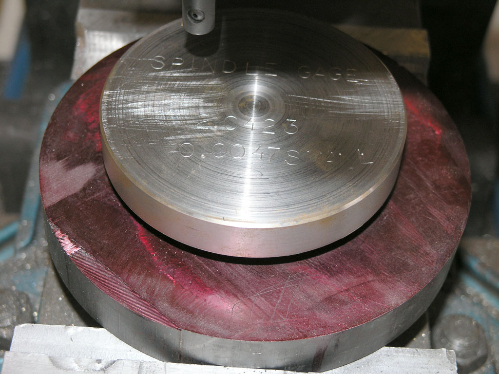
With the aid of the transfer screws, I was able to get a set of punch marks in place:

P1010413.JPG


<continued>
 
Next I got out my handy dandy pip-popper to line up on the pips:

P1010436.JPG


Easy gadgets to make in your spare time on a lathe. Not all that accurate, but it will do.

I went one size larger than recommended for the M10 tap, a "T" twist drill:

P1010437.JPG


Wes, I need your tapping stand to replace my crappy tap wrench!

P1010438.JPG


And there are the faux cam locks in place. It all fits on the spindle very nicely!

P1010439.JPG


<continued>
 
Next up is the center bore that fits on the spindle nose. But how to locate the exact center of that triangle of cam locks?

I chose a method that is pretty complex. If I were doing a third backplate (this is my second), I would make a fixture to go in an existing backplate and pick up the center at the same time I am using the transfer screws. However, this method works!

First, I want to level 2 cam locks at the bottom so I can use them as a reference datum for the height gage:

P1010440.JPG


Then I measured the top and bottom of the bore on the height gage, did the math, and now I know how far about the top of the leveled cam locks the centerline is located.

Next, I grab the workpiece and level it's cam locks. I start with a bubble level, and then use the height gage until the top of the cam locks are at the same height accurate to a thou:

P1010443.JPG


Then, I move the height gage up the proper amount to put the scribe on the center line and I scribe a line:

P1010445.JPG


I rotate to put the third camlock on the bottom and level with one of the other two and do it again. The intersection of those lines is the centerpoint. I double check with digital calipers (I was off and had to do it again! measure twice, cut once, yada, yada!).

P1010447.JPG


<continued>
 
Two screw machine length bits, two Silver & Demings later, I have run out of larger bits. I need to track down some really big S&D bits. Using the boring head is slow, so I want to get as close as possible. I do happen to have this big ugly 1 1/2" "corn cob" though:

P1010449.JPG


It's a pretty comical thing to run on a small mill, but it actually works great. The only caveat is it likes a lot of pressure when plunging or it chatters. So I hang on the wheel and we get a pretty decent hole.

But there is trouble in paradise. I am always double checking. I got the calipers and checked whether the edge of the center bore was equally close to each cam lock hole. No such luck!

I got measurements of 0.543, 0.575, and 0.500". So, rather than have to think about it too hard, I got out my CAD program and drew up what was happening:

Bore%20Error.jpg


If you can't understand what I learned from that, don't worry. It is described in lurid detail on my web site, link already given. Suffice it to say that the CAD program told me I was off 40 thousandths on the X-axis and a little over a thou on Y.

Hmmmm, sez I. Why the heck would X be so far off???? Aha! Sez I. Because the head is out of tram and I have moved it quite a lot in Z! Why is it out of tram? Because I was flycutting and broke a flycutter when it slipped. I didn't show that ugly incident, I just showed the nice indexable face mill. Of course somewhere in the back of my mind I knew you always gotta retram when you crash, but equally of course I hadn't done it.

No big whoop. I retrammed on the spot, and my CAD program told me exactly what I had to do to correct the mistake with the boring head. Onward!

So, now I had to "level" on those pesky cam locks again to match my CAD drawing. No prob, clamp a parallel to them and sweep with DTI just like tramming the vise jaws:

P1010450.JPG


Now center up on the bore with my Blake Coax. Love that darned thing: I had it from out of chuck to locked down and centered within less than a minute of sticking the Blake in a collet and lighting it up.

P1010451.JPG


<continued>
 
Now I bored, and bored, and then bored some more:

P1010454.JPG


At last I had a bore for the spindle nose that was fit for, well not a King, but maybe a plug gage?

P1010453.JPG


What the heck? Well, it's darned hard to measure ID's like that. When I made my first backplate, I made that plug gage. I even stamped useful data in it, such as the fact it is 0.0047" too small. This makes it a good gage to tell me its time to be really careful when it just fits as you can see it doing in the piccy above.

At this stage, I dialed in a little extra and cut 6 thou out. I wanted to be sure that before I took this thing out of that vise that it would indeed fit the spindle nose and would rather it too large than too small. We will see the method to my madness shortly.

P1010455.JPG


Behold this fully operational battle-cough, cough, err the backplates fits on the spindle nose just great first try with its camlocks. Yay! :big:

Now we gotta finish on the lathe...

<continued>
 
Okay, here's the deal: the work up until now has not been the money play, at least where accuracy is concerned. All I've done is used the mill to create a very solid way to mount that cast iron. What's more important is to machine the important features on the lathe in a way that ensures concentricity.

As a warm up to all that, the first thing I did was a little work on the collet chuck itself to make sure the bore on the back was concentric. I chucked a piece of scrap in the 6-jaw, turned it with light cuts so it was round:

P1010405.JPG


Then I stuck an appropriate collet in the collet chuck and clamped it down on that stock still in the 6-jaw. Now I used a boring bar and VERY light passes to make sure the back bore was running concentrically:

P1010392.JPG


It was out 2-3 thou before that operation, and before removing it, I remeasured and got 2 -3 tenths of runout. Quite an improvement! I should be so lucky as to have the rest of the work live up to that standard. ::)

After getting the cast iron onto the spindle, my first instinct on a workpiece is always to square it up. This piece is nearly too large for my lathe at 6". I had to place the tool holder in an odd way to get enough travel and clearance to turn:

P1010456.JPG


Don't mind the phonographing grooves--I didn't bother retracting the cutter when I moved back to start as I'm not done yet.

Eventually it all got square:

P1010457.JPG


The next thing I do may surprise you...

<continued>
 
To make really dad-gummed sure that backplate is true, my next step was to bore a proper bore for the spindle nose and then flip the thing over:

P1010458.JPG


What the heck? Why'd he do that???

Well, I had no way of telling how true my spindle nose bore was. It was made on the mill, not the lathe. Also, I had intentionally slightly oversized the bore.

But, the result was amazing. You can see from the blue arrow above where the ridge separating the two bores is. The amazing thing is that they look darned concentric even with magnification. They gotta be within a thou considering how little ridge there is, how symmetrical the ridge is all the way around, and that the bores differ in ID by a couple thou. I was feeling really pleased that all my crazy machinations with CAD programs and height gages had actually worked out so well. Who knew? (Sorry for the gloat, but I was genuinely shocked by this outcome!)

Here is where we stand after I knocked off tonight:

P1010461.JPG


That spigot goes into the recess in the chuck back. That same recess that I bored to true it up. This is the money shot for accuracy. I must get the fit between those two perfect. Accordingly, I stopped about 60 thousandths short and knocked off so I could start really fresh and do it right. I want it to fit so well that I need to heat the chuck a bit and freeze the backplate before they'll go together just right. After I've achieved that, it'll be time to test the runout for real and see how it all came out.

Keep fingers crossed!

Cheers,

BW
 
Just a question Bob, How do you know that the collet wasn't running out and not the chuck? I have one of those import collet chucks on my South Bend. It runs with in a thou. But the spindle bearings need snugged up also. I always assumed that a chucks pilot would be fairly true with the rest of the chuck? Also On the fit, I've always made them a tap fit. That way I can change it if needed. If you shrink the chuck onto the plate you might want to drill and tap some push off holes in case you get a new lathe someday?

Just some thoughts, Wes
 
It is possible it was the collet, I have seen that before on my ER. In this case, I used a new Lyndex collet, so I hope not! I guess the other possibility would be to try several collets.

I look at most of my projects as an opportunity to experiment and learn, so I often have backup plans or try multiple new things. In this case, I will start with the shrink fit. BTW, it will be a challenge for me to make that fit accurate enough to shrink! I also like your "push off" hole idea, so I will definitely take that approach.

If I either botch that by making the spigot too small or discover too much runout, I get to go to plan B.

Plan B is interesting, and I am tempted to go directly there, but I also want to get going on the Team Build. Plan B is to go with a too-small spigot and experiment with tapping the chuck into alignment the way you would a mill vise. The disadvantage is it just isn't as rigid as plan A. I like A the best if it works.

There is even a plan C, which is to fabricate an adjust-tru type arrangement so I can dial in the chuck. I have a Buck 6-jaw adjust-tru chuck that is a dream. You will note there is tons of excess diameter on the backplate. I can either mount some brackets for positioning screws or possibly turn a big enough bore to sink the chuck into the backplate with a rim containing 4 set screws. Now I can dial it in perfectly even if different collets have different runout. Plan C is pretty nifty. Not as rigid as plan A, but pretty foolproof as far as eliminating runout. Unfortunately, it is also the most work for me!

I'll get 'er done. I just need to see how many contingencies I get to before I decide it's good enough to get on with the Team Build parts. I'll settle for a thou as good enough to move on for the time being. Let's see how the next stage turns out. I had to work till late tonight, so no time in the shop to move forward yet.

Cheers,

BW
 
Bob,

When I purchased my cheapo collet chuck, and that is what they are. I tried three before I stopped sending them back as unfit for use.
These chucks are made for the mass market, and although they look very good, being ground all over, they just might as well be made by someone with an angle grinder.

So eventually I put my one 'right', by mounting it on a standard backplate, as I have done with all my chucks. I then ground the collet nose true, using an internal toolpost grinder.

It wasn't a million miles out to begin with, just a couple of 10ths, and coupled with cheap collets, when having a bit sticking out by three inches, it sure made it look 'wobbly'.

After grinding the nose, the cheap collets do look like they are made to very tight tolerances.

So it might pay you to look at the nose end rather than the back.

John

 
HI
I have to say Johns about spot on about the quality of these collet chucks. All the
ones I have looked at are at best shoddy and at worst badly made.
I have a collet setup on a Colchester thats about 25 years old still runs true. back when I bought it
it was knocking on the door of 500 GBP. You gets what you pays for.

Cheers Kevin
 
John, thank you. Indicating the nose will be one of my first tests once I get it mounted. It's something I've started doing on everything I buy that involves a taper after some experiences with ER chucks I'll get into shortly. Regrinding that taper, if necessary, will be one of the first things I do after CNC'ing the lathe as I expect it to be close enough I can live with it until then. That project, BTW, is underway, and not far off, just not on the front burners.

Kevin, you do get what you pay for for the most part, but there are exceptions. My cheap 800watt eBay (doesn't get much cheaper and grungier) ER32 collet chuck for the mill measures the same runout as a pair of new Bison ER32's I bought for a lot more money (3X and the Bisons were on sale!). I wrote earlier about a problem I was having breaking 1/8" end mills that I traced to runout in this chuck. I assumed wrongly it was the cheap chuck and ordered the Bisons only to discover it was a cheap collet! That's why I used an expensive collet on this exercise!

The one thing I don't like to futz about too cheaply on are my measuring tools. If I expect to be able to work to precision, I need to measure to precision. Hence I own a lot of expensive and obscure measuring instruments that some HSM's have just shaken their heads at. It is entertaining to compare results with the cheapies I started out with and see how they agree. For example, my Mitutoyo calipers (and no, I don't regard calipers as exotic expensive measuring instruments!) are no more accurate than my cheapies, they just have a nicer feel. My brand new Mitutoyo digital micrometer is no more accurate than my ultimate cheap box of verniers, they're just easier for me to read at a glance. I verified all that with both the micrometer standards and a high grade set of gage blocks I bought. OTOH, I my cheap indicators do not perform nearly as well as my Interapids. I have not tried to measure ultimate accuracy, but smoothness really matters when indicating something in so I shelved them.

In any event, my view is why analyze all this stuff endlessly at the armchair? We're machinists. We have the ability to make it right if it didn't start out that way for this sort of thing. Important skills for the machinist are to be able to diagnose exactly what the cause of the error is and to then figure out how to fix it. I'm still learning how to do that well, but I've had some good successes along the way. The correction on the center bore based on the CAD program analysis is a great example from this same project. Truing that spindle back was cheap insurance that does not foreclose other possibilities. I view it as valuable learning experiences to do something like trying to "accurize" this cheap chuck. I can always write a check for a nice $600 adjust-tru chuck later if it doesn't work out. I haven't because this chuck sat on the shelf for a year and a half unused. Most of my parts have been big enough I didn't think about the collets. Now the Team Build has changed that.

I'll document what I find along the way so others can learn too.

Cheers,

BW
 
Got the chuck shrink fitted to the backplate. It actually worked out very nicely so far as that all goes. More details on my website:

http://www.cnccookbook.com/CCColletChuck2.htm

The most finicky detail was to measure the bore on the chuck to a fine degree of accuracy. I eventually concluded it was 3.77259" after trying a variety of techniques and comparing the results. The best result came from a stack up inside the bore of a 1-2-3 block in the middle, precision gage blocks on either side, and precision pin gages in contact with the bore walls and gage blocks. I measured the actual dimensions of all these 5 components with my Mitutoyo micrometers after calibrating them against their standards. FWIW, the difference in the measured size of the stack and the "labeled" size of the components was 0.00065". That's not too terrible for 5 different components I suppose, but I was glad to have measured the real stack.

I then carefully turned the backplate nose to be 3.773" going into a 3.77259" bore. I got it a couple tenths too small by my mic measure, but was happy.

Upstairs then to the kitchen (wife cringes when she sees me carrying odd objects into her kitchen!), and the backplate went into the freezer and the chuck into the oven at 340 degrees. I left the pieces in their respective conditions for an hour to reach equilibrium. When I pulled them out, the chuck just dropped onto the nose very nicely. Off to dinner, and two hours later I came back to find a chuck shrunk onto a backplate. Cool!

Down to the shop to measure how well it all worked out. The test I decided to perform was to measure a "real world" situation. I would take 2 different sized parts requiring two different collets, insert them in the chuck, and measure the runout with a DTI on a magnetic base.

The first part was a partially completely faux camlock:

P1010463.JPG


The other part was a 0.250" pin gage from my set. I set up my DTI to measure the runout thusly:

P1010462.JPG


Each part was tested 3 times by removing the part completely from the chuck and reinstalling, although I did not remove the collet, just loosened it. You can see from the piccy that I was not happy. 0.004" runout. Drat! Can we do no better with these cheap chucks?

So I measured the taper without a collet as Bogstandard suggests. It was the identical 0.004" runout. This runout was all very repeatable, and that together with the fact the collets were accurate was strangely reassuring. The cam lock part was oddly less repeatable than the pin, but perhaps it wasn't quite as accurately made so I ignored that and decided that maybe I could dig out of this hole. My inspiration was to try the 3 different ways the chuck could go into the camlock holes on the spindle. Perhaps there was one "best way". So I marked the two with my Starrett Automatic Punch, and started collecting data. This procedure helped a little, but not a lot. I got the TIR down to around 0.003". It was also far better for the pin gage than for my camlock part. Rarely, I could get the pin gage down to 0.001". The camlock, OTOH, was sometimes out as much as 0.007". I went to bed thinking I would need to engineer an adjust-tru setup, which would mean a lot more work before I'd get much use out of the chuck.

This morning, I got up and went down to the shop thinking I was going to get started on that Adjust-tru, which would be a lot more work. Before doing that, I decided to check runout on the spindle nose itself. If that was way off, the lathe itself was in question. Good news there, the nose was about 2.5 tenths. In the process, I noticed some dust around and started cleaning up. Cast iron, after all, is nasty stuff. Then I had an inspiration: maybe the dust had deflected the chuck. After a thorough cleaning up of everything, spindle nose, backplate, taper, and collet bore, my eye next lit on my faux camlock. There was a little ridge at the unfinished end, so I ground that off.

With some trepidation, I started to test again. I was now seeing 0.002" and sometimes 0.001" TIR. Much better! Almost good enough to get on with. But then I had the LUCKY ACCIDENT that really made the difference. As I prepared to take down the chuck and go drill mounting holes (satisfied this would be good enough TIR for now), I forgot to move the DTI. It was still engaged. And I saw it move as I loosened the camlock nuts. Hmmm, says I. Can we use this?

So I loosened all the nuts, tightened them just a tiny bit past finger tight, put the indicator on the pin, and started my "chuck alignment procedure." I rotated to find which nut had the highest runout for the pin. I then tighted or loosened the nut until the DTI went back to zero. Once 2 of the 3 nuts were pretty tight, I went to the third and carefully tightened it up hoping the needle wouldn't move. It didn't. Now I measured both parts again.

Good news! TIR was now 2.5 tenths, just like the spindle nose:

P1010464.JPG


The taper was 2.5, the pin gage was 2.5, and the cam lock was more like 5 tenths. It was all very repeatable. I dismounted the chuck twice to be sure.

That nearly concludes our story. I still need to drill and tap the holes for the chuck mounting bolts, but I am very pleased at the accuracy even a cheap collet chuck can provide if you are doggedly persistent in tracking down and fixing sources of error!
 
Well done Bob.

If you hadn't gone to such lengths, and just wacked it on as normally would have happened, do you think that the same results would have shown themselves?
Or like myself, where these cheapo chucks have to be persuaded to tow the line by tweaking.

John
 
If I had just turned an "almost right" spigot on the backplate and bolted it up the way I did my first backplate, there would have been a lot of runout. I saw enough intermediate results to know that's true. Even if I hadn't done that initial truing job on the back of the truck and still did a precise shrink fit, there would have to be some error that isn't there now. Note that for many chucks it wouldn't matter. On a 3 or 6-jaw, you expect that. But, for a collet system, you expect a lot more accuracy and repeatability, else why bother with collets?

If you want the shortcut from all the careful backplate work, build or buy an adjust-tru style mounting from the start. This way you can just dial away all your errors. I wind up having to dial them away with a special procedure when I install the chuck.

The adjust-tru feature isn't that hard to engineer. You need 4 bolts that bear against the chuck body so you can dial it in. I was preparing to go that route anyway. If the current process of getting the cam locks to behave is too pesky, I may still go back and do so. But at this point, my plan is to finish with the chuck mounting. For those with more money to spend, buying a chuck with the adjust-tru feature built in may be worthwhile. My chuck is similar to the Lathemaster Eagle, which sells for $179. I'm pretty sure I bought mine 2 years ago on sale for a bit over $150. Now compare to Lathemaster's adjust-tru version which sells for $279, so you have a $100 premium. What's your time worth? I would guess it cost me an extra 4 hours for the work I did here. It was worth it to me just because I enjoy it and feel like I learned a lot. May not be worth it to someone else.

Also note that not every spindle is amenable to my techniques. My Lathemaster has that funky "faux camlock" arrangement that let's me dial in the last bit. You couldn't do that with a threaded spindle, for example, or even a real cam lock. Best to go with a real adjust-tru for those cases.

The other question I can't answer is how many chucks come out of the box with such a bad taper no amount of the type of work I did will fix it. There you'd better be ready to regrind that taper.

Cheers,

BW
 
Based on many comments here and elsewhere, and seeing some others' stands, I decided I need one before tapping one more tiny hole. While I intend to build a "standalone" stand, today's effort gets me a good part of the way and yields a functional tool.

I recently purchased a 0-1/2" keyless chuck for the mill, so I had a spare 0-3/8" keyed chuck available. It has a straight 1/2" shank that I held in the mill wth a collet. The first job was to make a way to turn it with a tap chucked. This was made from 1" aluminum round, knurled and split, with a 6-32 locking screw. Then I took a 3" piece of 1" aluminum round bar, turned down one end to 3/4" to fit in a R8 collet, and drilled/reamed a 1/2" hole through. Here's the pieces:

medium.jpg


With the round bar held in the mill spindle, I slide the chuck shank up into it and move the piece to be tapped underneath. Here I'm tapping the top of one of my new engine columns.

medium.jpg


The chuck can also be used on the lathe, as the bushing I made for the diestock is also bored 1/2":

large.jpg


The next phase will be to make something similar to what Stew built, shown on another thread.
 
Back
Top