Longboy's "TWIN REDEMPTION" Model Engine.

Home Model Engine Machinist Forum

Help Support Home Model Engine Machinist Forum:

This site may earn a commission from merchant affiliate links, including eBay, Amazon, and others.

Longboy

Well-Known Member
HMEM Supporting Member
Joined
Nov 19, 2009
Messages
813
Reaction score
548
Location
Tucson, AZ
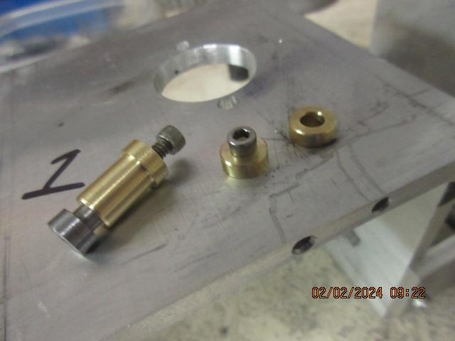
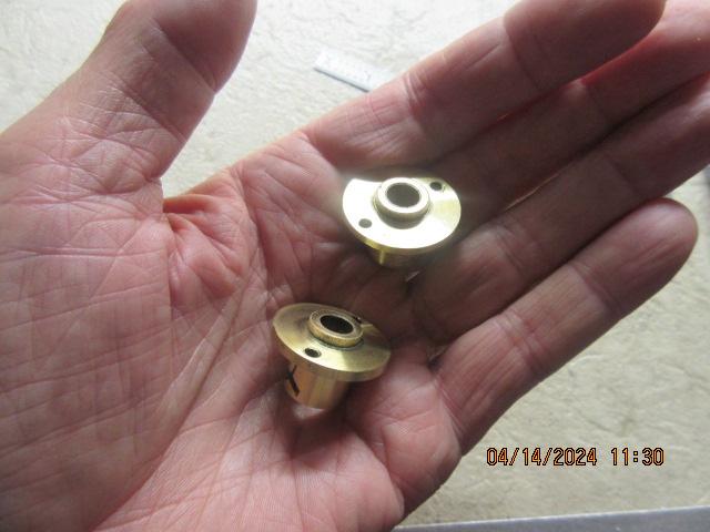
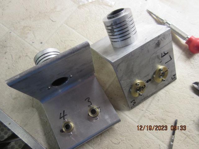
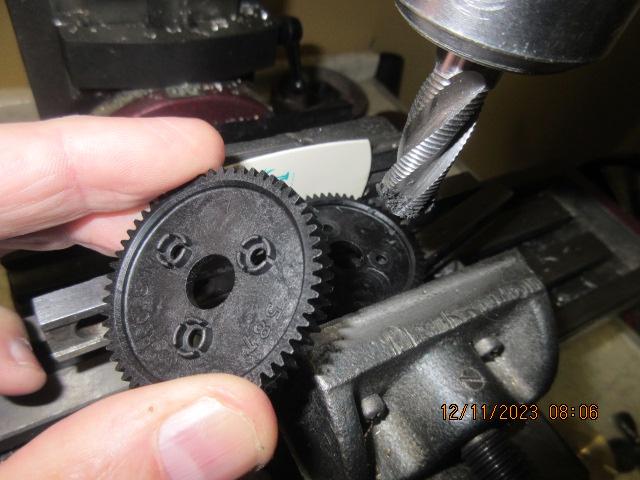
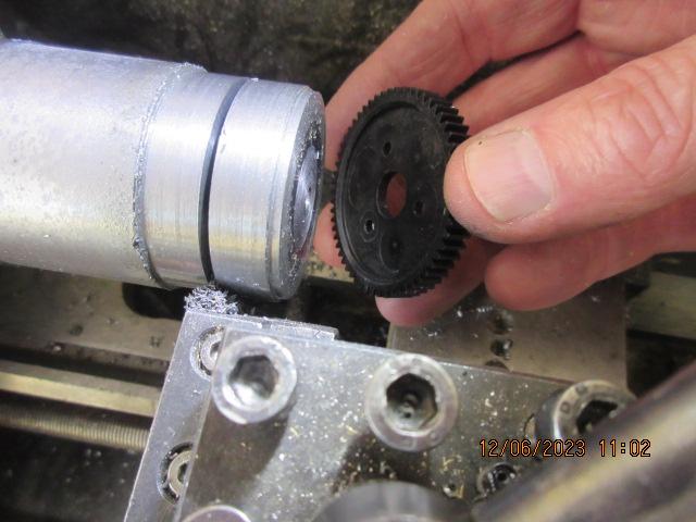
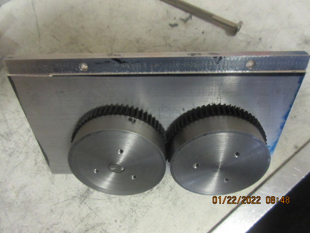
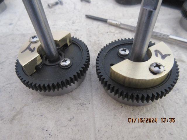
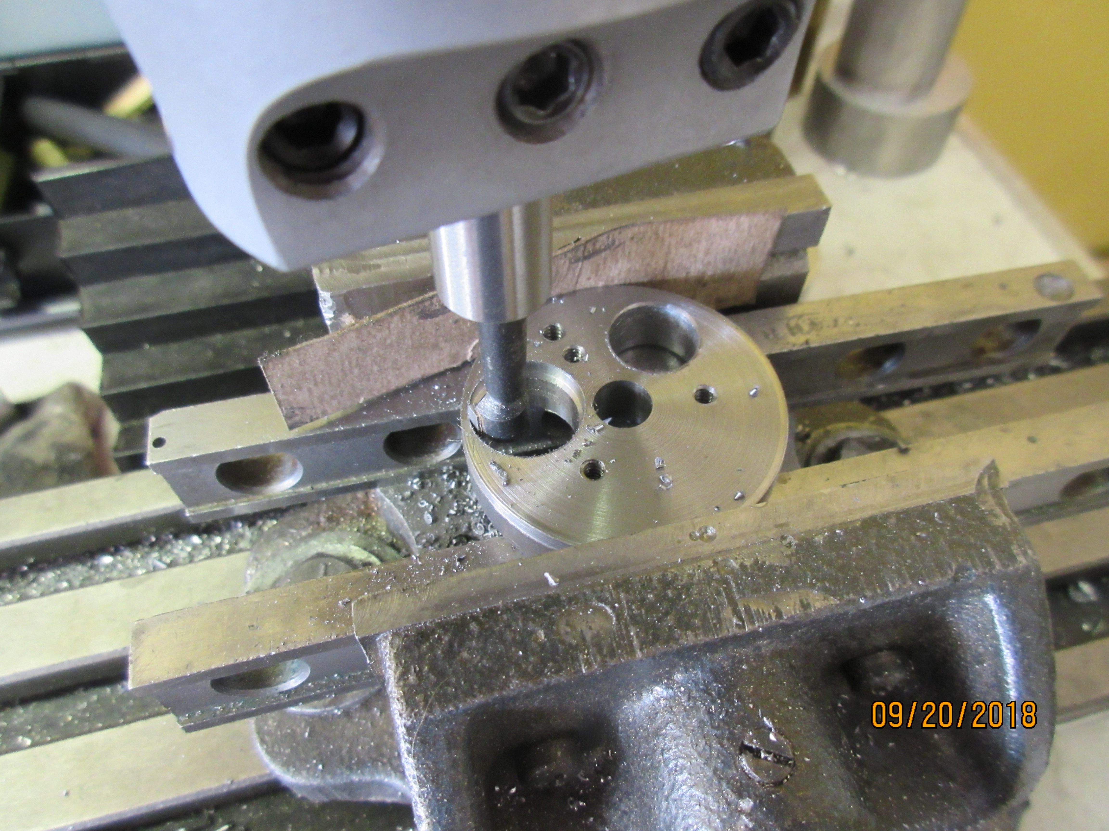
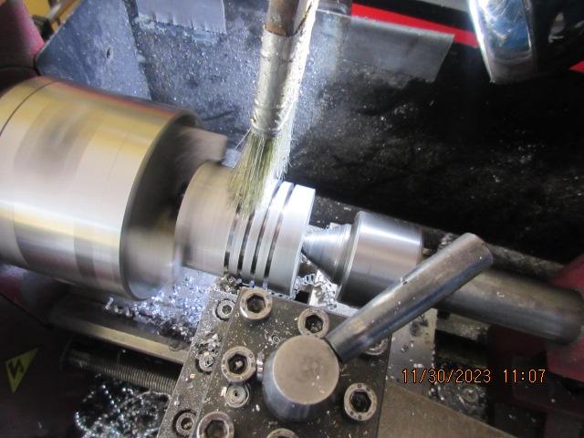
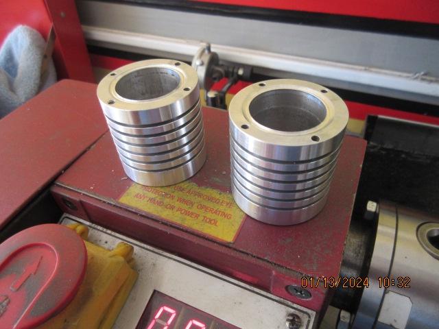
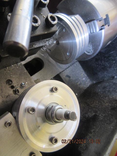
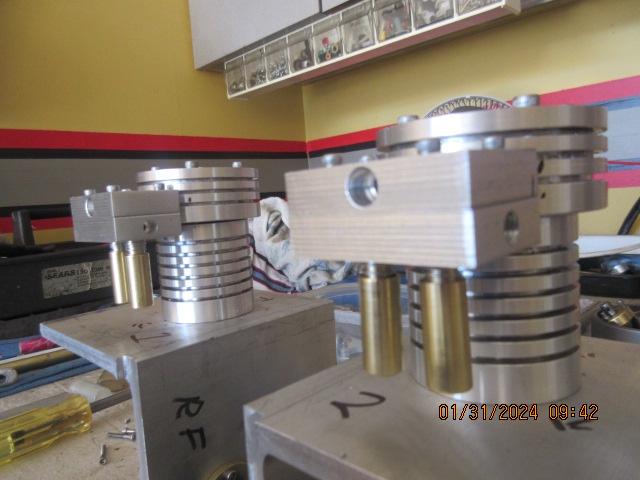
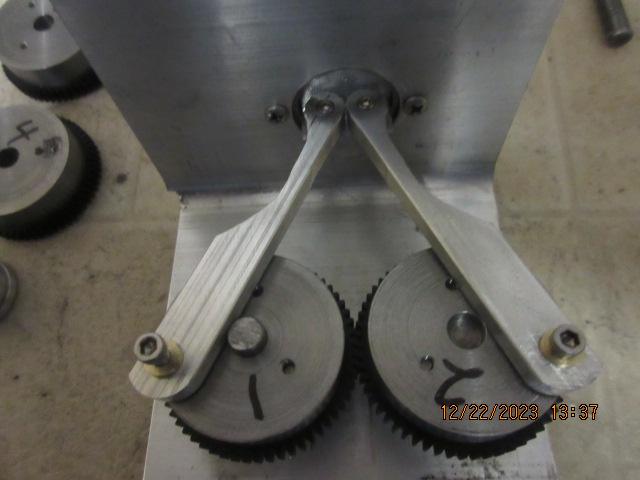
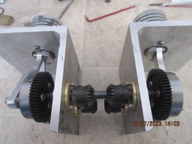
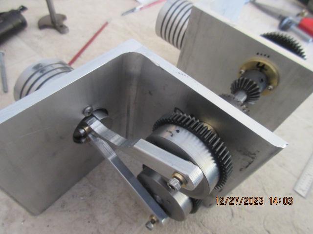
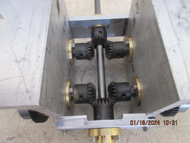
Last year's "SPLIT MONO" engine was a unique effort and a successful build. What would a two cylinder version look like? There are two ways to go here......and inline twin with both cylinders on one side of the crankshaft or a cross cylinder design, like an opposed engine with one cylinder each side of the crankshaft. I got to play with a lot of gears in the process.....and it ended up in a surprise finish! :eek: The road to the T.R. engine starting this week!

qvMTUed.png
 
Last edited:
This is a couple months into the build. 4x4 aluminum angle, 4 in. long time 2 pieces. The cylinder hole on the horizontal is offset on the length from center to accommodate the camshafts. Two screw attachment. A pair of valve lifter holes at the front top.

1713119673869.png


Brass lifter body, steel lifter with 4-40 socket head adjuster screw lock in with 6-32 set screws coming in at the frame edge.

xBqqWQY.jpg


Two bearing carriers per cylinder are necessary for a split rod engine for the crankshaft stubs and are mounted in their bore throughs from equal off set to the center of the cylinder mounting in the vertical leg of the 4x4.

MSryLon.jpg


1713126197869.png


And mounted in place on frame.

Gp6EaBm.jpg
 
Last edited:
Using a different part number for the Traxxas spur gears and less $$$ at the time ordered. Milling the raised areas on the hub off for flush fit to the webs.
ke56Wv5.jpg


4T less and an eighth inch shorter in diameter. Cutting back the diameter of the web round stock for the fit.
XIFCj33.jpg


Fitted to the backside of webs with three 6-32 machine screws.

ap6p7v4.jpg


Piggy backed to the backside of gear and web to balance the piston/ rod assembly, a half moon shaped brass counterweight.
3QYZVJp.jpg

0XyHqSb.jpg


One machine screw with blue Loctite. Additional weight reduction of the steel web will complete the primary balance.
eCwUyu2.jpg

8NrA7Xg.jpg
 
Last edited:
Twin port valve blocks are made up from quarter inch bar stock.
IjOcCwa.jpg


Self contained units with brass guides, leaded steel valves, o-ring seals. Four corner bolt together. A single fine thread 1/4 in. screw mounts blocks to head.
gFNWjfm.jpg


A flat is machined to lower side of heads. Drilled for both ex. and in. ports at 5/32 in. Brass tube inserted with o-ring seal between head and valve bock. Upper half of valve block drilled for mounting bolt to head.
gYHmPJ7.jpg

4M7Xyzl.jpg


And as it appears projecting out from head/ cylinder assembly!
w89JgPg.jpg
 
The pistons for a dual rod engine are somewhat weird. They are longer and have a more solid core as the rods are attached to their lower third, therefore heavier. A flat is machined across the bottom for the rod attachment. The depth of cut determined by the rod centerline to match piston centerline.
zaV4u5E.jpg


A couple of parallel 4-40 threaded holes for the small end attachment. A standard plumbers O-ring for the combustion sealing.
9mR8R5q.jpg

H6Dq7U3.jpg


Rods have the same strangeness to them. With the crank webs offset to the side of the cylinder, you get steep rod angles at their 3 and 9 O'clock positions. The outside cut aways in the rods are to clear the bottom of the cylinder liner in motion.
fOJsFuP.jpg


1713765783778.jpeg
 
Last edited:
The two halves of the engine mockup. Have to square up with end plates to the frame. Run a 5/16 in. transfer punch across through web to web to come up with a critical shaft centerline.
JfHMhy8.jpg

VkBizXg.jpg


With the lower crank endplates in place, how the bottom end will look with six bevel gears. I did not particularly like the vendor's gears here. They are dark end to end with the heat treat. I order 6mm hole thru and re-drill to 5/16in. A couple would not drill cuzz of the hardening. Ordered others from a different provider after the experience.
e4mZWOv.jpg


The cams come into the frame at 90 degrees to the crank/output shaft. My lobes crafted in brass this time, the easiest to cut and file a profile to. Slipped onto a transfer punch and by line of sight location to the vertical leg of the 4x4 pieces.
1713894538517.jpeg


The marking drilled and bushed and the lifter adjust screw range will take up the valve timing needs.
1713894954219.jpeg


The upper end plates have the distributor and cam drive shaft. MXL sprockets will mate the crank and cams.
1713895347877.jpeg
 
Last edited:
The cams driven by some .5Mod, 24T brass bevel gears. Three up front and two more for the distributor.
1714242663075.jpeg


The bottom shaft will get a shaft stop collar to keep the gears in mesh.
1714242882472.jpeg


The ign. points will sit on the vertical leg of the 4x4.
1714243055996.jpeg


And its cam will be the shaft stop collar for the other side.
1714243232193.jpeg


Thinking about distributor being in center of the shaft valley........but no. Needs another crossmember to support the dist. body and further limiting access this area.
1714243513996.jpeg


Cam drive shaft will head to the back of engine and mount to top end plate. Some relief for the gear teeth milled in the end plate.
1714243841573.jpeg


And the assembly ready to go.
1714244262075.jpeg


1714244178924.jpeg


An aluminum bracket for the insulated stud on the points bolt down with a couple of 2-56 screws to the top deck.
1714245083295.jpeg

1714245115345.jpeg


And from the top side......the geartrain connected.
1714245210127.jpeg
 
Back
Top