Longboys "GEMINI" Twin I/C Engine.

Home Model Engine Machinist Forum

Help Support Home Model Engine Machinist Forum:

This site may earn a commission from merchant affiliate links, including eBay, Amazon, and others.

Longboy

Well-Known Member
HMEM Supporting Member
Joined
Nov 19, 2009
Messages
811
Reaction score
546
Location
Tucson, AZ
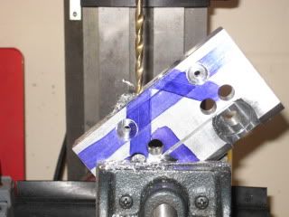
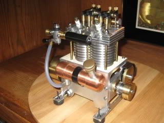
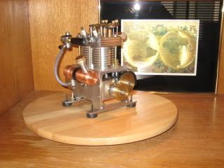
This was going to be my winter project.........my winter started late August! :D I have a couple single cyl. I/C's and wanted to advance up to a muti-cyl. engine. 2 cylinders is a basic step, let me have at it! With ideas starting up, I went to Windows paint ( the poor mans CAD) and layed out a few basic 2D drawings. The GEMINI twin is the result.
IMG_0830.jpg
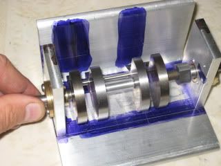
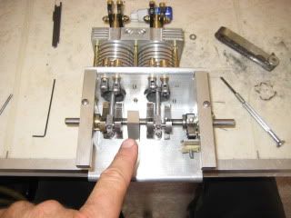
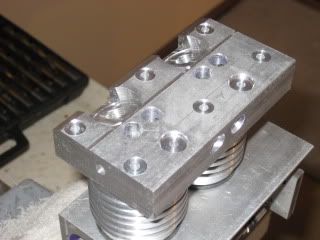
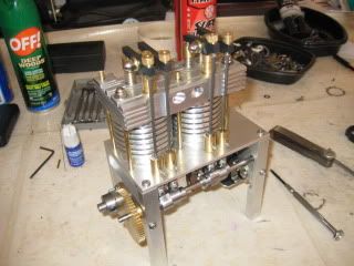
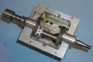
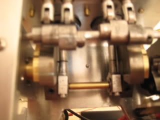
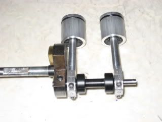
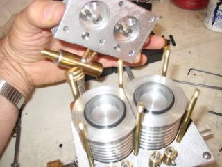
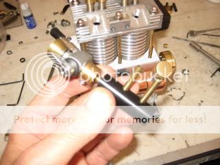
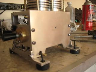
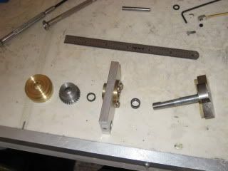
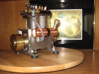
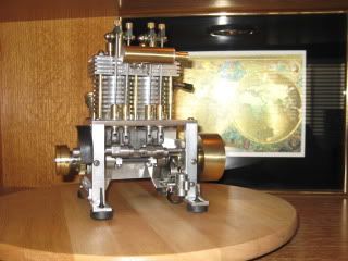
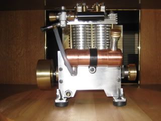
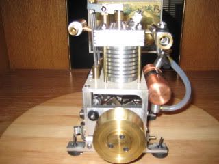
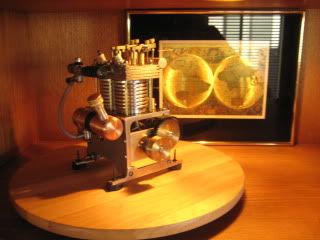
An open 360 crank design of 20 CC's its first run was Nov. 27th. Some disapointments in the journey. Along the way I had to remake the crank webs and cyl. head and I learned alittle bit more from the experiance. The GEMINI story starts this weekend. :)
 
This should be a very a very interesting build to follow. I can not wait to see it. Gotsta' have LOTS of pictures though ;D

BC1
Jim
 
Using the same approach as my SENTINEL engine, a piece of 3x4 inch alum. angle is the backbone and cyl. base of Gemini. A pair of crank webs for each con rod and a center bearing. 5/16 end supports with a brass bearing carrier are bolted to the angle piece.
IMG_0699.jpg
IMG_0704.jpg
IMG_0797.jpg
IMG_0796.jpg
 
I like to start out making some standard engine parts. Radiators (air cooled), pistons, rods and cam lobes.
IMG_0549_1.jpg
The radiator over 7/8 in. bore DOM cylinders with o-ring head gasket. Pistons on the stub.
IMG_0544.jpg
Cutting fins.
IMG_0710.jpg
Parting off piston.
IMG_0577.jpg
Offset shaft hole in cam lobe stock. Seems like yer always cutting off/into some kind of metal here.....if I don't cut off my blood supply I can keep going! ;D
 
Aluminum angle can be an ideal piece to use in modeling. You have the vertical leg to set the overall height and stance of the engine and the horizontal leg to mount the cylinders to. Angle would also be a good basis for opposed engine construction. You still have to have four point mounting to a base in a vertical engine so a couple legs have to be fabricated. Multi piece frame up not as rigid as billet or castings, I use #6 stainless screws with star washers to hold it all together.
IMG_0708.jpg
IMG_0782.jpg
Shown here boring the horizontal leg to recieve the cylinders. Cylinder center line is 2 inches apart.
 
!!!!! I like this! allot!
would be interesting to know how to do the cam and timing.
 
Brass is king for flywheels. This is a 1 x 2.25in.dia. Weight is 20 ozs. I came across a posting by cfellows regarding a collet mounting for the flywheel on a twin cyl engine he built. There was an illustration in his post and and I made a split steel collet for the 5/16 dia. crankshaft I was using. This method wasn't working for me. The longer the collet, the thicker the metal taper at its hub and my three #8 screws would not compress the split to grip the crank.
IMG_0728.jpg
The sollution was a change in material and a separation of the tapered collet from its hub. A Delrin collet was made with a split. Inserted into the flywheel, the collet rises about 3/32 out from flywheel hub. The three screw brass retainer easily compresses the collet so the retainer and flywheel hub is flush. I made about 3 samples of the Delrin in different lengths to get the flush fit here. You can use a film of auto grease or liquid plumbers teflon on the Delrin for quick release from the crank/ flywheel. This collet mounting is ideal! The flywheel runs true. Cosmetically, the brass retainer has no split being a two piece system.
IMG_0836.jpg
 
A full skirt piston 7/8 dia. and alloy rod join the crank throw. In the final configuration of GEMINI the crank webs are 3/8 wide. Started with 2in. dia 12L14 steel cut down to 1 11/16th in. to clear the cam lobes.
IMG_0806.jpg
7/10ths ounce was removed from the hemisphere of the webs, the piston rod assembly weighs 1. 26 OZs.
IMG_0872.jpg
A brass disk was made, cut in two and super glued to the outside of the webs to bring into primary balance.
IMG_0871.jpg
With the crank end plate in the vise, insert the assembly into bearing and hope for a stay when placed in any position.
IMG_0870.jpg
Those are neo magnets on the outside of webs to complete the balance, however not used as the supplemental brass overlay is close enough. :eek:
 
That's a great looking little engine Longboy. Thank you for the posts and photos which contain lots of interesting tips for beginners like me. Please keep the posts coming, I will be following with interest.
Jim
 
You are welcome Jim! A 2 x 3/4in. alloy piece is used for the head. Combustion chambers are bored .250 in. deep, 1.125 diameter to accept the DOM cylinders.
IMG_0814.jpg
IMG_0816.jpg
A mockup of frame, cyl. with radiators and bare head. Now lots of locating and drilling for porting, spark plugs, valve guides, studs and rocker pedestals! A center drill puts the tapper in the underside to help guide the brass studs.
IMG_0823.jpg
IMG_0821.jpg
 
Valve guides holes drilled to receive a set of brass guides. The sparkplugs will be CM-6.
IMG_0731.jpg
.
IMG_0734.jpg
The inboard valves are the intakes. Looking at these 3 post build photos, you see the sparkplug pad directly in line with the valve guide. The pad is slanted down and prevents a direct drilling straight into the valve guide and if drilled diagonally into guide would break thru the surface of pad.
IMG_0883.jpg
I got alittle too fancy with the sparkplug pad. ::) The solution was to up end the head in the mill vise and drill thru both valve guide holes to a point about 1/4 in. beyond intake guide. Then 90deg. to intersect. The intake now has a dog led port and the extra holes are sealed by the guide insertion and an aluminum plug is pressed into each end of cyl head and finished over.
IMG_0885.jpg
IMG_0886.jpg
A central exhaust exit means the outboard guides call for diagonal drilling. Brass tubing for the muffler is then placed into port.
IMG_0772.jpg
All holing done, I can start to dress the head.
IMG_0776.jpg
 
I make the cam lobes separate from the shaft. Its quicker with no possibility of ruining the whole if you mess up a lobe but the lobes are a little more bulkier being created with a hub and set screw to tie them to its shaft. You can also play with the timing of individual lobes by advance/ retarding them but a minor feature as once the running engine smooths out its set and forget.
IMG_0247.jpg
I start with 5/8 steel shaft, offset one jaw in 3 jaw chuck on lathe and drill 3/16 in. for a stainless shaft. Over to the mill the stub is locked into mill vise with the lobe blanks overhanging from vise and the flanks are milled in the appropriate position related to the offset shaft hole. Hand filing creates the profile then.
IMG_0790.jpg
A set of roller lifters was made with brass guides with 2-56 thread guide pins. The bearings are R 168zz, same as used in con rod big end.
IMG_0791.jpg
 
Here is a rough in of the lifter/cam. I used a Delrin pin in the bearing and seams to hold up well. The ignition is mounted inboard and is a Tecumseh point set.
IMG_0789.jpg
1/2x1/4in. Steel rocker arms open the valves at a 1:1 ratio. Square cut for spring retainer clearance.
IMG_0739.jpg
Mounted on a pair of brass pedestals, they pivot in brass bushings secured with plated acorn nuts. The lock nut set is made with a 5/16th threaded brass rod with a straight knurl across the threads. You get an excellent grip with thumb and forefinger so no wrench on a hex nut here to set clearances. Rocker arms are flame colored with propane torch. I wanted a gold tone but that seems to only happen in a very narrow heat range and couldn't get good results with these small parts. (use brass next time Longboy)! The deep turquoise provides a nice contrast to the other metal here! 8)
IMG_0890.jpg
IMG_0741.jpg
 
It is looking good. I am following you with interest and learning heaps along the way. Thank you for the posts and the great photographs.
Jim
 
IMG_0798.jpg
With the major parts completed time to get to final assembly and start up. I have a twin with 2 inch bore centerline. 4 crank webs and a center bearing. Using 3/16th in. crank throw pins. Tighten it all up and I have binding rotating the crank by hand. Loosen up the setscrews on throw pins....binding gone but the crank is loose now. Either condition it won't run. So I play around with it a few hours, trying to find that compromise: a solid crank that rotates freely by hand in its bearings. So it starts to feel reasonable now so I continue assembly, set valve and ignition timing and try to start..........10 seconds of running and it eats out one of the flywheel side crank bearings. Add another bearing plus its replacement for 3 miniature roller bearings here and start. Eats the center bearing out then. :'( So I know this isn't going to work. Too many individual pieces in crank. Segments of crank offset of centerline ( runout). Crank throws to crank centerline not totally parallel and crank webs a little too narrow to support the throw pins. Time to step back for a few days, get on the web and review others model in line twins, I/C and steam. Is LONGBOY in over his head this time? :eek: Can GEMINI be saved? ??? The story continues...
 
Herculesenginecrank.jpg
This is a photo of the bottom end of the Shores "Little Hercules" engine, a known quality. Outboard webs and no center bearing. In doing Gemini with an open crank and being air cooled, the 2 inch bore centerline allowed full radiators and room for center bearing and inboard pair of webs. Dropping these items from Gemini.....that would make for a long crank pin filling that distance to both con rods. It wouldn't look right, may be get some flex in a long crank pin if not stiff enough. Water cooled engines can have shorter bore centers, how is it handled with an air cooled engine? Shorting up the bore centers would require a new angle frame and cyl. head.
IMG_0863.jpg
With new bore centers at 1 1/2 inch now, the bottom end. Frame was shortened 5/8 in. A shorter cyl. head was duplicated to original, the exhaust ports are now Siamese to their exit from cyl. head to get headers between pushrods. The previous posted wider webs have up sized#8 set screws and a shorter crank pin remains 3/16 inch. A Delrin "dumbell" fills the space between con rods.
IMG_0868_2.jpg
 
IMG_0810.jpg
The radiators where flat milled and butted up against each other installed on the deck of a new angle frame. Still plenty of room for the o-ring gaskets.
IMG_0813.jpg
Back to where I was now, the new crankshaft configuration turns easily by hand with the end plates drawn tight to frame and crank throw pin locked in the webs. The flywheel side bearing carrier now sports an Oilite bushing in place of the three R1810ZZ bearings which remain in the crankshaft nose bearing carrier.
IMG_0875.jpg
The muffler shown here was soldered to the head pipes, after a few minutes running the bond failed. A new larger diameter muffler stuffed with stainless pot scrubber material was secured using a flanged threaded collar and sounds better.
IMG_0838.jpg
The intake is 5/8in. Delrin to independent intake ports and supplied by a TRAXXAS carb. Just like automotive practice where they use moulded intakes to keep fuel systems cooler, the carb never gets hot in running.
IMG_0839.jpg
The slab side of angle frame. You can hang a couple of spare tires here......maybe a life boat. :big: But we all know the fuel tank resides here! Gemini dances on four rubber feet from Ace Hardware.
IMG_0827.jpg
Crankshaft thrust control is with bushings up against the roller bearrings. If the crank "walks", it will cock your con rods causing binding up in the piston and stall the motor. A brass pulley for accessory drive finishes off the crank nose.
IMG_0874.jpg
Come back tommorrow for the conclusion, the beauty shots and see GEMINI run! Thm:
 
Longboy, you are amazing! That was just about a complete engine rebuild in record time: crankcase, crankshaft, head, modify the radiators on the cylinders, main bearings and you must have rebuilt the camshaft as well. Full marks for sheer bloody persistence :bow: :bow: :bow:

You deserve to hear it running and all fettled by Xmas day. I look forward to seeing (and hearing) it.

Thanks for the journey and Merry Xmas

Jim
 
A second I/C in 2 years of my design after the Webster build. It can be difficult creating standard type engines without plans or layed out drawings.
IMG_0833.jpg
Always going to be "issues" along the way.
IMG_0832.jpg
Dynamic models can "almost" tell you its needs. Your job is to find out.....
IMG_0834.jpg
........is it the fuel system, cam or spark timing, or mechanics? ???
IMG_0837.jpg
You sit back to rethink, redesign, rework, review! :idea:
IMG_0835.jpg
Read the forums, pick up hints, ideas, proceedures. Thm:
IMG_0831.jpg
Cuzz you know someday you will get it to this! woohoo1 [ame]http://www.youtube.com/watch?v=apF_uoF1Nao[/ame] Hey thanks for following along in the GEMINIS creation. Any questions or comments welcome and enjoy all my engine models at YOUTUBE/LONGBOY4. Dave.
IMG_0906.jpg
 

Latest posts

Back
Top