


Sshire
Well-Known Member
- Joined
- Jun 29, 2011
- Messages
- 936
- Reaction score
- 259
Liney RV-2 - Four Heads Are Better Than One
Part 1 - Crankcase
I know. I know. It’s been 5 days since I’ve posted a new engine build, but I had to wait for Richie, my UPS guy, to bring a chunk ‘o 6061. After the double-wide RV-1, I’d had enough of those large parts and was itching to get into some 0-80 thread tapping.
If you’re not familiar with this Liney Machines engine, here’s a description from their website.
“The RV-2 is a four cylinder opposed style engine with gear driven valves and timing. The design is inspired by the internal combustion engines that power so many of today’s general aviation aircraft (and VW's!). The pistons are 3/8" with a 1/2" stroke driving a one piece aluminum crankshaft that rides in miniature ball bearings. The "RV" designation is for "rotating valve". The valve design incorporates a pinion gear on the crankshaft which times a one piece rotating valve.”
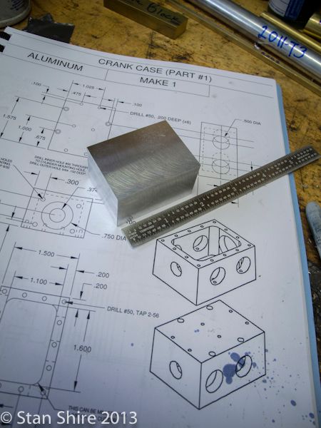
The plans are well done with one part per page (sometimes one part on two pages) and most have the drawing and a 3D line drawing of the part. Nice touch.
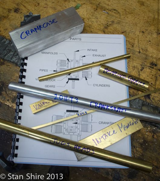
All metal was gathered. Mostly standard and I had nearly half of it in my stock. The only type I haven’t yet worked with is the 2011-T3 aluminum which is used for the one-piece crankshaft. Now, there’s yet another new thing. I’ve only done built-up crankshafts, so this should be an adventure.
A group portrait before most of it becomes chips.
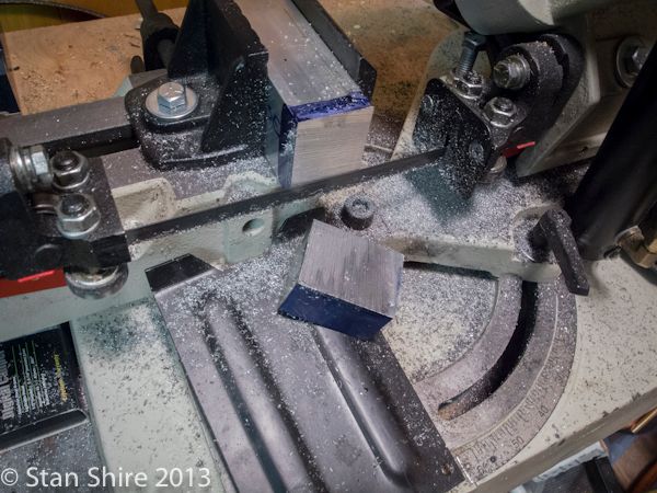
Removing a piece of the 1.5x2” stock for the crankcase.
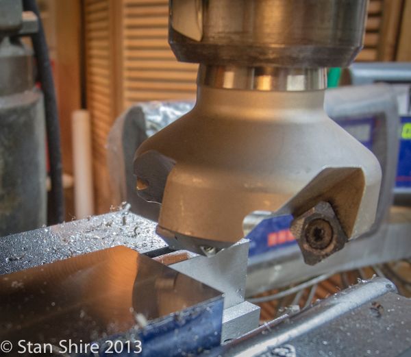
Squared up the 6061 with the face mill. I decided to treat myself and actually turned each of the 4 sided carbide inserts one turn. I had noticed a slight amount of roughness to the surface and looked at the inserts with a loupe. All four had edge chipping which was because I forgot to change from the aluminum finishing insert the other day when I had a piece of cold-rolled on the mill.
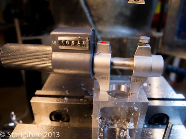
Hit this dimension bang on.
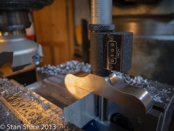
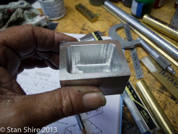
Now we have a square crankcase blank, most of which will become chips.
I marked out the block for my roughing cut so I have an idea where to stop. The aluminum roughing end mill went through the piece like it wasn’t there. The opening will be 1” deep.
Cuts were .100 per pass.
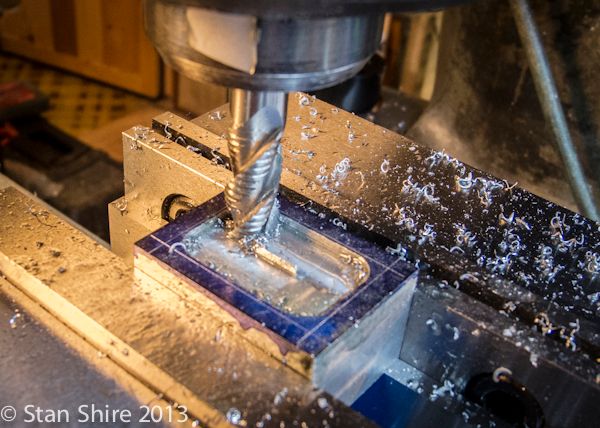
Halfway there.
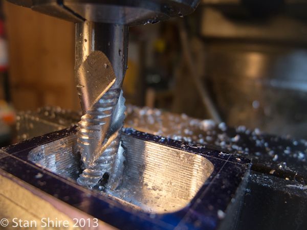
After the roughing mill, I changed to one of my “good” end mills for the finishing passes. I define “good” end mills as the ones that are made in the USA and look like someone took the extra time with it. They also cut much more smoothly than my “everyday” Chinese imports. It also amazes me that I can actually get my hands clean when I finish in the shop.
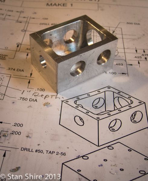
Time now to put lots of holes in the crankcase. Between these holes for the con rods and the two for the crankshaft, there must be another 20 or so that will be drilled and tapped.
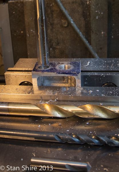
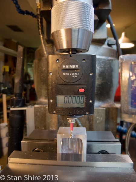
Locating edges and center for the crankshaft holes.
There is one hole at each end. The smaller one is .374”. Drilled undersized and reamed. The other end has a .75” hole. I used a series of drills to get to around .65. My largest is a Silver and Deming. I know that the S&D bits shouldn’t be used in a keyless chuck or you may need a 16” pipe wrench to get the chuck unlocked (DAMHIKT). The bit was put in a collet and drilling ensued.
When I was boring the 2” deep hole in the RV-1 valve block, I used my “import” brazed carbide on HSS shanked boring bars. CHATTER!!!. I cranked the Bridgeport’s speed down. I cranked it up. I increased the feed. I decreased the feed. I poured copious amounts of cutting fluid into the bore. I ran dry. An all around annoying experience.
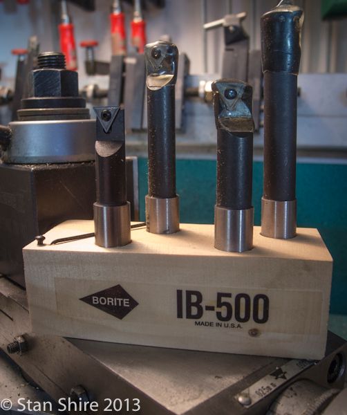
I knew that the problem was the 2.5” boring bar flexing. After looking at various possibilities. HSS vs Solid Carbide shanks. Indexable vs brazed. Etc. Kennametal vs Criterion vs whoever.
I talked to these people. Very helpful. Made in Michigan. Set of 4 solid carbide .5” shank. Comes with 4 inserts, extra screw and wrench. $115.00. BTW, the Criterion set was $315.00.
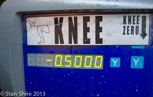
I used the knee power feed and got the best finish I’ve ever had when boring with the Criterion head on the mill.
Tomorrow, all of the tapped holes and call the crankcase done.
Part 1 - Crankcase
I know. I know. It’s been 5 days since I’ve posted a new engine build, but I had to wait for Richie, my UPS guy, to bring a chunk ‘o 6061. After the double-wide RV-1, I’d had enough of those large parts and was itching to get into some 0-80 thread tapping.
If you’re not familiar with this Liney Machines engine, here’s a description from their website.
“The RV-2 is a four cylinder opposed style engine with gear driven valves and timing. The design is inspired by the internal combustion engines that power so many of today’s general aviation aircraft (and VW's!). The pistons are 3/8" with a 1/2" stroke driving a one piece aluminum crankshaft that rides in miniature ball bearings. The "RV" designation is for "rotating valve". The valve design incorporates a pinion gear on the crankshaft which times a one piece rotating valve.”
The plans are well done with one part per page (sometimes one part on two pages) and most have the drawing and a 3D line drawing of the part. Nice touch.
All metal was gathered. Mostly standard and I had nearly half of it in my stock. The only type I haven’t yet worked with is the 2011-T3 aluminum which is used for the one-piece crankshaft. Now, there’s yet another new thing. I’ve only done built-up crankshafts, so this should be an adventure.
A group portrait before most of it becomes chips.

Removing a piece of the 1.5x2” stock for the crankcase.

Squared up the 6061 with the face mill. I decided to treat myself and actually turned each of the 4 sided carbide inserts one turn. I had noticed a slight amount of roughness to the surface and looked at the inserts with a loupe. All four had edge chipping which was because I forgot to change from the aluminum finishing insert the other day when I had a piece of cold-rolled on the mill.

Hit this dimension bang on.

Now we have a square crankcase blank, most of which will become chips.

I marked out the block for my roughing cut so I have an idea where to stop. The aluminum roughing end mill went through the piece like it wasn’t there. The opening will be 1” deep.
Cuts were .100 per pass.


Halfway there.

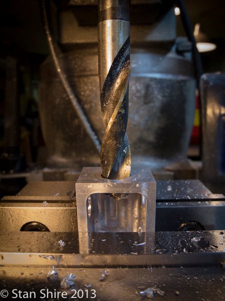
After the roughing mill, I changed to one of my “good” end mills for the finishing passes. I define “good” end mills as the ones that are made in the USA and look like someone took the extra time with it. They also cut much more smoothly than my “everyday” Chinese imports. It also amazes me that I can actually get my hands clean when I finish in the shop.

Time now to put lots of holes in the crankcase. Between these holes for the con rods and the two for the crankshaft, there must be another 20 or so that will be drilled and tapped.

Locating edges and center for the crankshaft holes.

There is one hole at each end. The smaller one is .374”. Drilled undersized and reamed. The other end has a .75” hole. I used a series of drills to get to around .65. My largest is a Silver and Deming. I know that the S&D bits shouldn’t be used in a keyless chuck or you may need a 16” pipe wrench to get the chuck unlocked (DAMHIKT). The bit was put in a collet and drilling ensued.

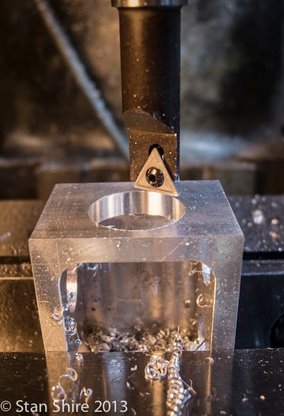
When I was boring the 2” deep hole in the RV-1 valve block, I used my “import” brazed carbide on HSS shanked boring bars. CHATTER!!!. I cranked the Bridgeport’s speed down. I cranked it up. I increased the feed. I decreased the feed. I poured copious amounts of cutting fluid into the bore. I ran dry. An all around annoying experience.
I knew that the problem was the 2.5” boring bar flexing. After looking at various possibilities. HSS vs Solid Carbide shanks. Indexable vs brazed. Etc. Kennametal vs Criterion vs whoever.
I talked to these people. Very helpful. Made in Michigan. Set of 4 solid carbide .5” shank. Comes with 4 inserts, extra screw and wrench. $115.00. BTW, the Criterion set was $315.00.

I used the knee power feed and got the best finish I’ve ever had when boring with the Criterion head on the mill.


Tomorrow, all of the tapped holes and call the crankcase done.
Last edited:
")
