KB Draws Steve's V-8

Home Model Engine Machinist Forum

Help Support Home Model Engine Machinist Forum:

This site may earn a commission from merchant affiliate links, including eBay, Amazon, and others.

kustomkb

Project of the Month Winner!!!
Project of the Month Winner
Joined
Dec 14, 2007
Messages
1,181
Reaction score
31


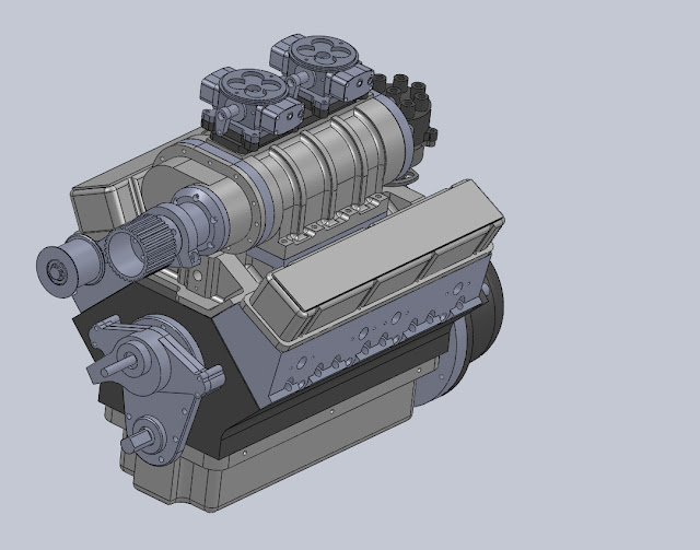
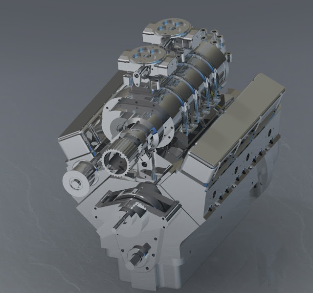
If I ever get around to making some chips for this beauty, I will change the title of this thread.

For now this is where I am at. I have quite a few hours invested in the computer modeling which will pay big dividends when it comes time to make some parts. It also helps me visualize the machining steps and verify the fits of the components. It's nice to make your mistakes on the computer because unfortunately there is no "undo" button in metal. But with this many parts, I know there will be times that I wish there was.

DV8%252520front.JPG


DV8.JPG


Nice work!
What are the chances you converted to metric as you went? :big:
 
/// said:
Nice work!
What are the chances you converted to metric as you went? :big:


Good question!

I also would like that the dimensions be in metric system.

Cheers,

Alexandre
 
KB, looks good! Maybe I can coax you to show a section through a cylinder bank ;D That's always good stuff for the non CAD guys.

Now, when you guys say metric, do you mean you want to see 7.9375mm for a 5/16" dimension or 8mm? I've thought about doing a drawing for a single of some sort, but I work in metric. That would certainly kill the market in a good part of the world. Two designs would certainly be possible.

Greg
 
8mm ofcourse ;D

Alex,
I use Autocad Inventor(learning it... slowly) at work and I made a start on converting to metric.
Problem is, I just don't get much free time to do anything on it.
I could stay back another hour or so after knock-off, but I get home late enough as it is :mad:
 
Thanks fellows and a big thanks to Steve for the plans!

I am more comfortable working in imperial, but it wouldn't be hard to swap out fastener sizes as you went along.
Converting dimensions to nice round metric numbers on the other hand would certainly be an undertaking.

Just drawing this thing from the plans is quite time consuming (for me) I couldn't imagine the time it must have taken to do the design work.

Sure thing Greg, here are a couple section views, as you can see it is just the shell for now. I have the internals drawn, just need to assemble it all. Then maybe I can post an exploded animation.

I have a 3-D pdf but it is too big to upload here.

DV8%252520X-Section%2525201.JPG
DV8%252520X-Section.JPG


How's this for some "bling" ;)

DV8%252520chrome%2525201.JPG


Thanks Steve, will do!

At least you can go out to the shop and look at the real thing, I am still just dreaming.
 
When you get it all completed can you send me a copy? Would make great garage art.

I assume you've got quite a few renderings since you've released the plans. I'm eager to see a pic of your garage wall when all of them are printed out and pinned on :D
 
Looks nice KB can I ask what CAD system do you use? I'm accustom to NX6 and Catia rendering looks like stuff you can do in NX I'm sure most CAD systems now can do realistic renderings. I have done a few of the part for Steve's engine in my spare time in NX I have the block, cylinder heads, intake and crank shaft done. Still have a ways to go.
Anyway nice job KB!
 
Thanks Doc.

I am using solidworks. I've been chipping away at it over the last 8 months. I started with the more complex pieces too. I would consider myself a beginner considering the full potential of the software.

From what I understand, NX is a more powerful platform but costs more too.

The photo rendering is only available in the premium edition. I just quickly applied a chrome finish and dropped in a stock background before I went home. This was applied at the assembly level which is why the whole thing looks shiny. If I applied the finish at the part level then I could get a variety of finishes which would probably look better.

Would you mind posting a couple of pics? I'd like to see how the ports on your intake met up for comparison.

When it comes time to do the machining I want to try doing the majority of the heads, block and intake on the fourth axis in one set-up.

Cheers!
 
Here are a couple pics of the intake model.
And a link to a short vid.
[ame=http://youtu.be/f9mNR5OngfQ]http://youtu.be/f9mNR5OngfQ[/ame]
[ame]http://www.youtube.com/watch?v=f9mNR5OngfQ&hd=1[/ame]

intake man1.jpg


intake man2.gif
 
Cool, looks real nice.

I like the spot faces, I'll have to add those too. What do you use for screen capture?

I like the rads as well. I am planning on adding rads after everything is modeled to try and blend all the parts together.

I guess we could do some fancy surfacing/porting with a long ball nose where the intake ports meet. ;)
 
The screen capture is part of NX and the vid also was captured with NX.
I use NX at work most of the time and Catia part of the time so I do know my way around NX pretty well. I have access to 3d pdf also and really like the features with it. I usually model some thing up then spend some time tweeking it till it looks like I want.
Thanks KB I'm off to bed 5:00 am comes pretty early still have to work my real job for awhile yet :big:
 

Maybe SW has a similar screen capture function...

Leucetius, that's beautiful! Got any more?

 
At any time in SW you can choose "save as" and select type ".jpg". If you are rendering you want to render to file.

Applying finishes and patterns to a model can take a lot of time. trying to match machining parks or other visual features takes some effort. I don't usually do it unless I'm board. I'll dig one up later.
 

Latest posts

Back
Top