Imagineering's Stuff - Dykstra Beam Engine

Home Model Engine Machinist Forum

Help Support Home Model Engine Machinist Forum:

This site may earn a commission from merchant affiliate links, including eBay, Amazon, and others.

imagineering

Well-Known Member
Joined
Dec 6, 2010
Messages
96
Reaction score
14
Hi Guys.

I've decided to separate my Loco and Beam Engine threads & copy over the text from my original Thread.


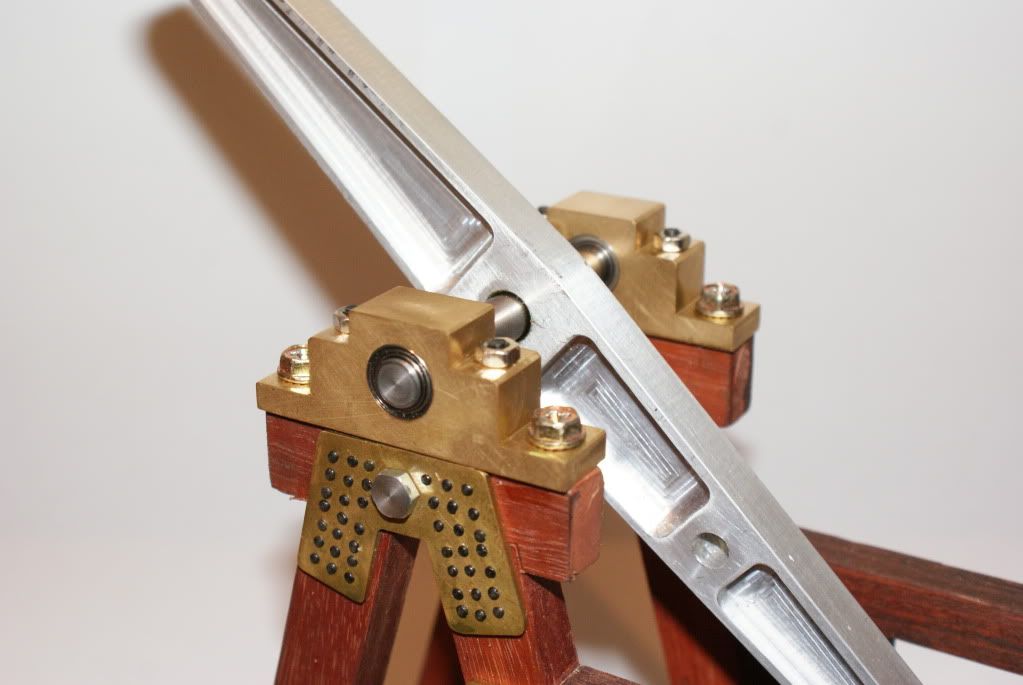
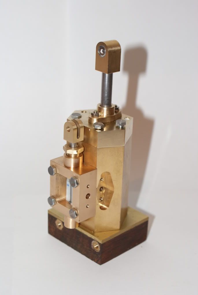
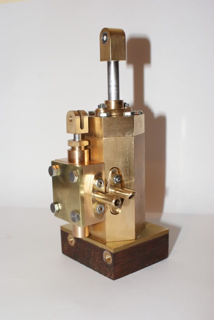
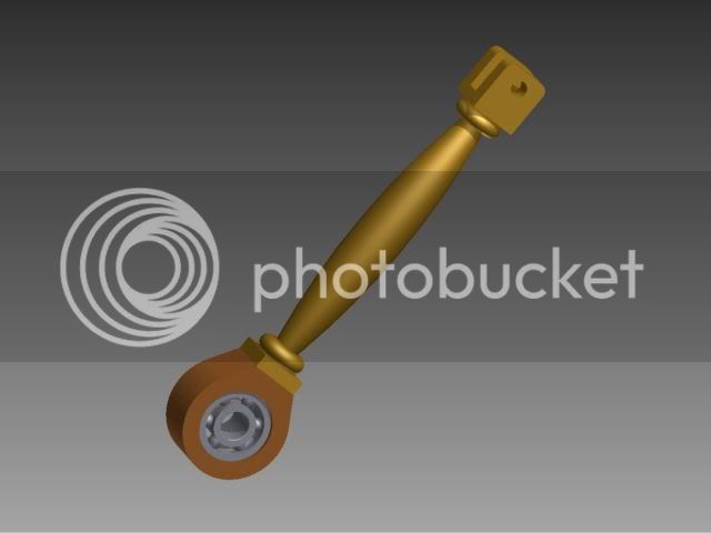
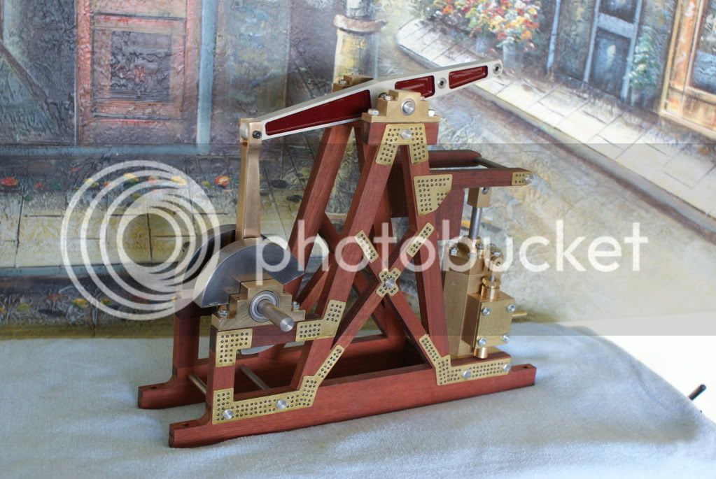
Peter, (Doubletop), has persuade me to put up a few photos of my version of Gerry Dykstra's Beam Engine.
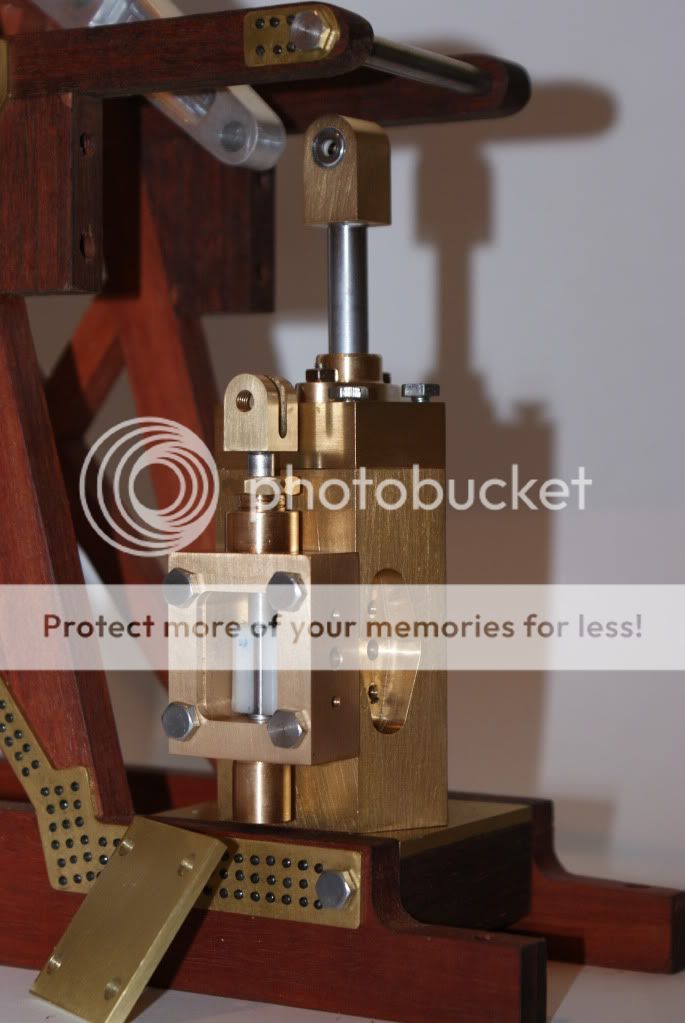
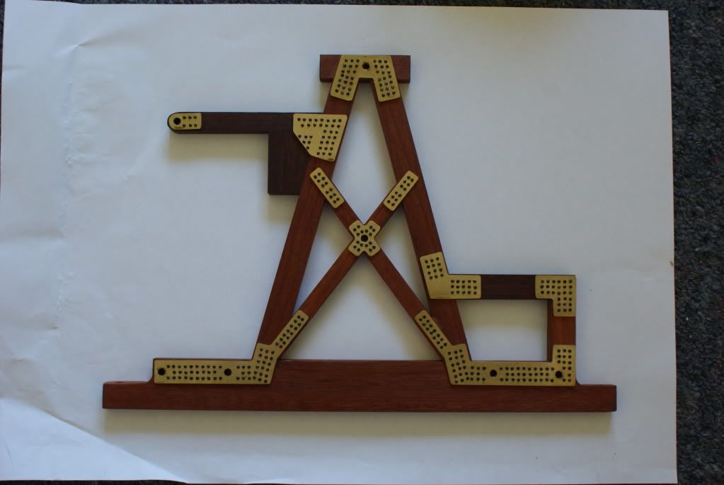
Double Sized, in Metric, (thanks Ken), with Frames timbered in Jarrah.
DSC03517.jpg

DSC03519.jpg

DSC03518.jpg

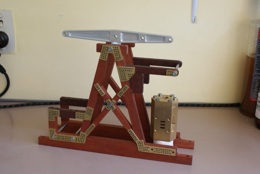
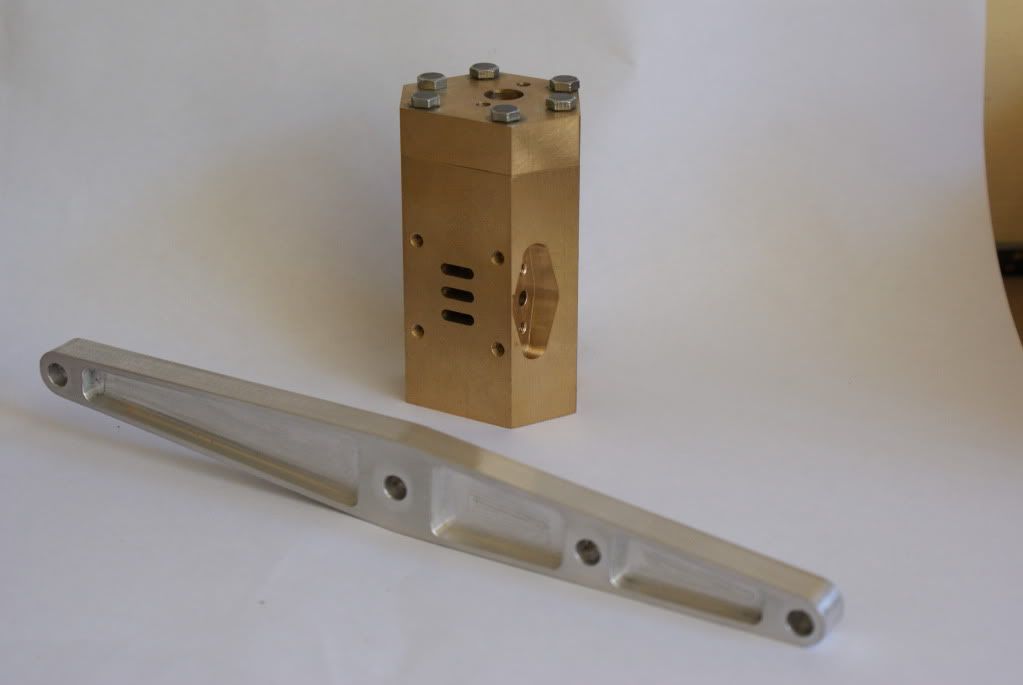
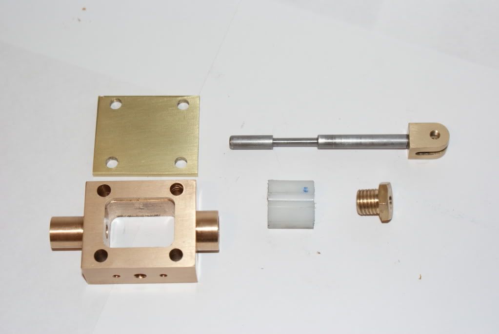
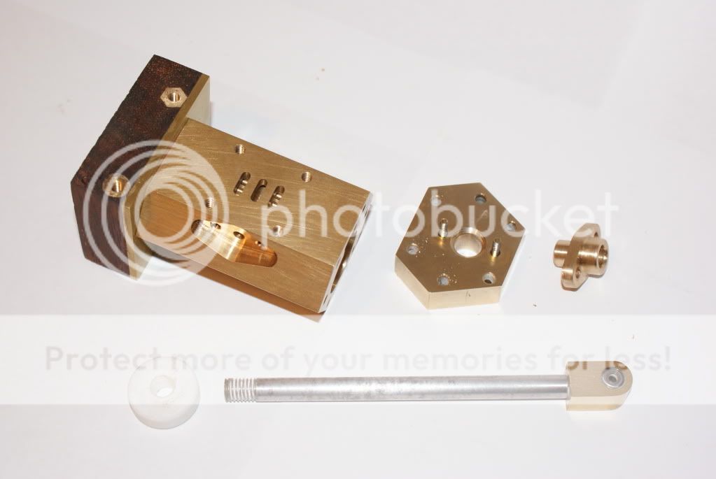
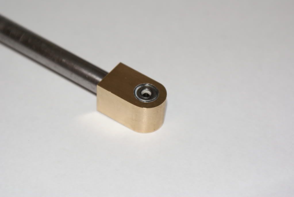
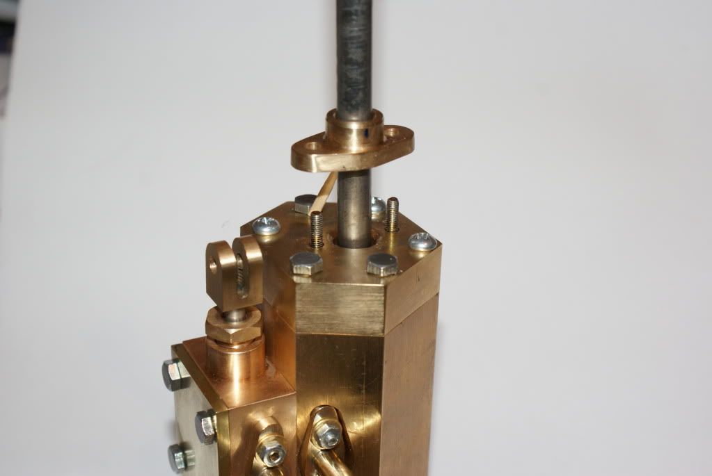
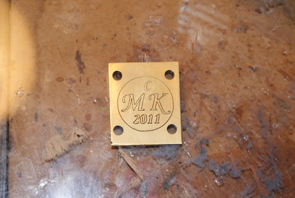
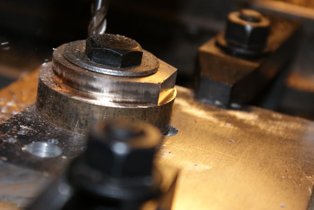
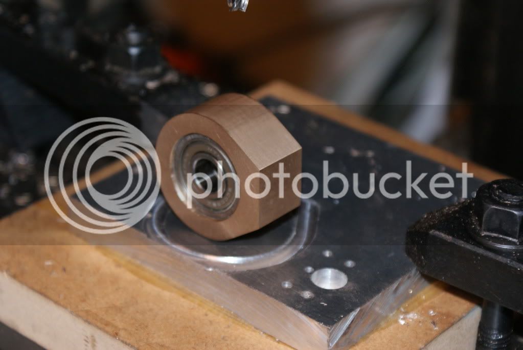
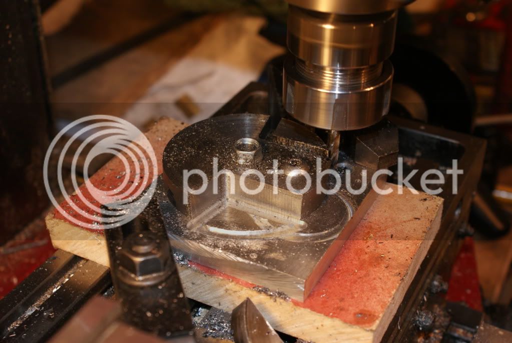
The Brasses were drilled & profiled on my Sieg CNC'd SX3 Mill.
The Brass Braces are 'nailed' on using cut down HO-Rail Track Pins.
This will be a long work in progress, as I have now got a 7 1/4 Gauge Live Steam Loco sitting in parts in the Workshop needing some TLC. (refer the other 'Imagineering's Stuff' Thread).


Murray
 
Hi Guys.

It's been a while, but I've been working on the Beam Engine & other things instead of Posting to the Site.

So, here's the work to date . . .

I machined the Beam Trunnions from Brass & fitted 2 Ball Bearings to each.
I've stripped more than my share of Photocopiers & Printers etc, so I have a ton of extremely small Bearings to play with.
4mm Brass Nutserts were epoxied into the frame to take the Screws, (to be replaced with Studs later).
This build will have Bearings wherever I have room to place them.
DSC03624.jpg


The SteamChest was turned & Machined from solid Brass, the Valve from PTFE. The Pivot Joint is a solid Clevis type, the Valve actuation Arm will carry another Ball Bearing.
DSC03636.jpg


The Cylinder has been posted here before, but shown here with PTFE Piston and Little End which carries Miniature Ball Bearings stripped from deceased Computer fans.
DSC03635.jpg


Close-up of the Little End. These Bearings are 8mm OD x 4mm Wide.
DSC03627.jpg


The Assembly temporarily posed for the Camera.
DSC03631.jpg


And posed in place. I tried without success to get a 53X60X20mm block of Brass for the cylinder base so reverted to a laminate of 4mm Brass Plate epoxied to a piece of Kwila hardwood with 4mm Nutserts epoxied into the sides.
DSC03628.jpg


I now need to make a number of Studs for the Cylinder/Head & ValveChest/Cover areas, and fabricate the Inlet/Exhaust Headers.

Meantime . . . back to the Workshop.

Murray.
 
Great work I like all your creative changes, wooden frame and the upscale.

Mine is chunnering away - I need to strip & pretty it up and mount it - somehow rather loath to tear it down - but I'll get round to it.

Regards,
Ken
 
Hi Murray,
Very impressive work. I built the Mary beam engine and run it quite a bit at shows. I am constantly refitting the split bearings on the beam ends and linkages so the miniature bearings you installed should help tremendously.
gbritnell
 
Thanks for the comments guys.

Pre-assembly is a great tool for finding faults ???
While setting up the Photo Session, I just twigged to the fact that, the Piston Rod Gland will seal perfectly to the Cylinder Head but not to the Piston Rod :mad:
I'll have a go at parting off the lower section of the Gland and Loctite it into the Cylinder Head, I'll then recess the Head for the Packing. As this Engine will only be run on Air, heat won't be an issue.

Murray.
 
Hi Murray, is that Kwila wood you used a 'common' wood in NZ or is it an "exotic" type of hardwood? Does it allow for adhesives of any kind to be effective in joining pieces together, same for the other wood that you used. Both species look terrific. Also, I had to think about what you are planning on doing for sealing the piston rod. I think I understand now, sort of an inverse setup of sorts. Beautiful craftsmanship by the way. I'm liking the rivets on the splicer plates, they are very eye catching.

BC1
Jim
 
bearcar1 said:
Hi Murray, is that Kwila wood you used a 'common' wood in NZ or is it an "exotic" type of hardwood? Does it allow for adhesives of any kind to be effective in joining pieces together, same for the other wood that you used. Both species look terrific. Also, I had to think about what you are planning on doing for sealing the piston rod. I think I understand now, sort of an inverse setup of sorts. Beautiful craftsmanship by the way. I'm liking the rivets on the splicer plates, they are very eye catching.
BC1
Jim

Hi Jim,
Kwila is a sustainable Hardwood from Papua New Guinea, and Jarrah, a species of eucalyptus, is an Australian Native AFAIK.
Both Timbers have a problem with Glue, we have a product in NZ called 'Gorilla Glue', a polyurethane adhesive that absorbs water from the atmosphere & foams as it sets, filling the pores of the Timber.
The Jarrah is a better looking Timber, ranging in colour from deep brown to bright red, and has better 'stickability'.
The Splicer Plates and Rivets are essential to the integrity of this build because of the Glue problem.
Finish is common Boiled Linseed Oil. I've made Furniture from Jarrah, and usually use 'Danish Oil' as a finish.

Murray.
 
Well, fixed the stuff-up by parting off the bottom of the Gland & Loctiteing it to the Cylinder Head as planned.
I now have room for some Graphite Twine or PTFE Tape between the Piston Rod & Gland.
DSC03641.jpg


Also fitted a few Studs & fabricated the Inlet/Exhaust Headers.
DSC03640.jpg


Haven't got any M4 Threaded Rod, or M4 Bolts long enough for Head Studs or SteamChest Studs so that will need to wait another day.
Couldn't resist, so I fired 10Lbs of air up the Inlet, Valve is moved up - Piston moves up, Valve down - Piston down.
Glad some things work every now and again.

Murray.
 
Murray

Its looking great and you are making good progress. I think you had only just started the valve chest when I last came round. It won't be long before its running. Then you will need a boiler............

Pete
 
Thanks for the wood info Murrray, sounds like those woods are extremely close grained and perhaps a bit oily in nature. Here in the states we have Gorilla Glue, or snot, as it is often referred to. It is quite aggressive in nature but seems to stick to the world very well. I'm enjoying watching your progress here, keep up the fine work. :bow:

BC1
Jim
 
bearcar1 said:
Thanks for the wood info Murrray, sounds like those woods are extremely close grained and perhaps a bit oily in nature. Here in the states we have Gorilla Glue, or snot, as it is often referred to. It is quite aggressive in nature but seems to stick to the world very well. I'm enjoying watching your progress here, keep up the fine work. :bow:
BC1
Jim

Hi Jim,
Watch the Kwila as it can be quite stringy. The Kwila Splinters are best got out of your Fingers straight away or else they fester quickly. It seems that the closer to the Tropics a Timber originates, the more toxic it is.
The Jarrah machines beautifully and is my pick of the two. I was WoodTurning for about 5 years or so, and have had a few pieces of Jarrah in the Lathe. This Timber is so hard, sparks can be seen occasionally from the Turning Tools. I've never had a bad physical reaction to Jarrah Splinters or Dust.
Another one to get hold of for machining is 'Ironbark', often used for railway Sleepers, (ties), here in NZ & Aus.
It's dull grey and boring to look at though.

Murray.
 
I decided to try 'Drag Engraving' today, so set up in the Mill, a broken 6mm Mill Bit that had been ground to a sharp point.
I created a ToolPath, spun the Tool up to 1800rpm & dragged it around the ValveChest Cover.
It worked OK, but with a few reservations. It's proved the need for a good set of parallels and the need to get rid of my Y-Axis backlash.
DSC03651.jpg


I've re-designed a few bits 'n' pieces to give the Beam Engine a bit of a 'Victorian era' feel about it.
I'll turn the Conrod in Brass or Bronze with a bit of shape to it, instead of the original milled square design.
I started making the Big End by boring a bit of 45mm Bronze Round bar to fit two Ball Bearing races side-by-side.
This done, I chucked it in a Bolt-Down Fixture and CNC Profiled it thus;
DSC03645.jpg


And here's the result.The square face will be tapped M8 to take the Conrod which has yet to be drawn & made.
DSC03648.jpg


Murray.
 
Murray

It looks like you decided to leave the hacksaw on the shelf and let the machinery do the hard work.

BTW thanks for doing those thrust washers for me. It was all back together in 20 mins and ready for another test at the track

Pete
 
doubletop said:
Murray

It looks like you decided to leave the hacksaw on the shelf and let the machinery do the hard work.

Pete

Yep, the arm was getting a bit tired from hacking them out from Round Barstock in the first place.

Progress today is thus;
DSC03656.jpg

Still need to fettle & polish the Toolmarks out of them.

Murray.
 
As well as trying to find paid employment, I seem to spend more time in the Workshop than updating this Thread.

This last week saw the Cylinder and ValveChest installed permanently, the Beam painted and the Crankshaft and Conrod completed and installed.

DSC03704.jpg


Slowly getting there . . .

.
 
It's looking good Murray

Pete
 

Latest posts

Back
Top