As a lad I was grinding cranks - in a refurbishing machine shop - and we had a locking clamp that was used for final linishing of the big-end crank journals. (Aside) the micrometer adjustable V-Block that used the grind-stone on the 3rd side when grinding eccentric and crank journals to size actually produced 137 - or whatever large prime number - of flats, as will happen with the geometry of angles and machining. These "flats" needed the adjoining peaks to be linished to get a perfect round journal, hence the final linishing tool with emery. Of course, main journals always ground a true round.). When making model cranks, I use a similar locking tool - called the self-grip wrench. The setting of the wrench is just to "nip" the emery while the shaft rotates at my slowest speed = 50rpm. As soon as the torque of linishing has dropped to almost nothing (not many rotations) the emery is progressed to an unused new part, then linishing continues. FREQUENT Micrometer checks needed - almost every linishing pass - more frequently as you get to size. And watch for any taper or out-of-parallel of the journal... - turn the tool upside-down for alternative passes, to reduce error from a tapered pressure of the grip. The advantage of locking pliers, compared to hand gripped devices, is that the "lock" gives a fairly accurate repeatable position. Adjusting the screw can give sufficient "feel" to increase or decrease the gripping pressure. If you have hard, sharp, serrated jaws that are not suitable for gripping the emery strip, a strip of aluminium (I use 1mm thick scrap sheet) can be stuck onto the jaws with your preferred goo.. (even masking tape..) and the grips will function perfectly well for linishing. I have half a dozen grips, of different sizes and shapes, and there is always a grip small enough for the journals I have made (1/4" wide x 1/4" dia. smallest).
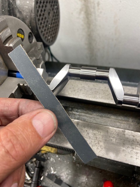
Of course, a home made adjustable grip as per photo
IMG_6009.jpg is just as good!
Incidentally, I use a 50% paraffin and lathe-oil (7W) mix when linishing in the hope that as the carborundum erodes the surface metal, the fluid motion will help move the crap away without build-up in a spot that could deteriorate the shape of the part.
And finally wash the journal in a spirit cleaner (paraffin, diesel fuel, WD40, white spirit, or whatever is your chosen cocktail...)
then a water + detergent wash in the ultrasonic cleaner (A small one is only £20 on £&@y!) to eliminate any remaining carborundum dust (embedded) from the surface... Rub the surface hard with a clean white paper tissue (nose tissue, or loo paper) and when it does not pick up a dark shadow the surface is clean.
There is such a lot of "knowledge" in every process.... someone should publish this website as a book. Tubal Cain wrote many with his accumulated knowledge...
Well done Basil!
K2
PS: I found this on U-tube: It off-sets the crankshaft so the journal being ground becomes the centre of rotation:
But see the V-block beneath the front of the journal? - just in font of the operator, next to the splash-guard and below the crank journal.
This is the calibrated V that relates to the surface of the stone so you can add a measure cut from the grinding wheel. The cutting point of the wheel forms a third side to the "Vee" - and as such the journal will try and "notch" its way around with any play (even the fraction of a micron) allowing the circle of rotation to cause the stone and flats to oscillate forming a prime number of small curves with points between: The same a s a 20p or 50p coin. The diameter at any point is correct, but the distance of the mid-way of diameters varies with the rotation to an error equal "to the distance of free-motion from the centre of rotation in the grinder". A hard concept to grasp, but there is tooling to drill a 3-sided hole with a drill with 2 cutting edges, a 4-sided hole using a drill with 3 cutting edges, etc. - Sounds impossible, but it is a mathematical predictable and real machining job! The extarct below explains explains the Reuleux triangle principle :
- The square hole machine works on the principle of Reuleux triangle. It states that if Reuleux shaped cam is rotated in a square guide it can convert the rotating motion of shat and rotor into square guided by the square guide. The rotary motion can be provided by means of a motor or hand drill. A flexible coupling is required to rotate the shaft eccentrically i.e. at a distance from the centre of the chuck of the motor. This will help the Reuleux triangle shaped cam to rotate in the square...
https://www.ijsdr.org/papers/IJSDR1...e,drill a square shaped hole on the workpiece.
The "reverse" is happening in the crank grinding machine, where the necessary machine play (and flexibility of crankshaft) allows the crank to "oscillate" between the 2 faces of the Calibration V-block and the grinding wheel face, such that if takes off a tad too much metal at one point, that permits a tad too little metal to be machined when the "flat" appears at the faces of the calibration Vee - in turn. The machine is so designed that the "resonance" of number of flats is a very large prime number. The journal is ground a couple of microns "big" to then permit a linishing operation (constant pressure, fixed size gap, with large contact arcs) - which takes off the peaks between the lows of the multifaceted journal.
Light reflected on the journal just after grinding shows the "lines" of the various flats. It is fascinating to see and appreciate what is happening! - Blame Reuleux! - D.S.
K2