how would you machine this part?

Home Model Engine Machinist Forum

Help Support Home Model Engine Machinist Forum:

This site may earn a commission from merchant affiliate links, including eBay, Amazon, and others.

JohnT

Member
Joined
Jul 16, 2009
Messages
16
Reaction score
0
Bar1Print.jpg
 
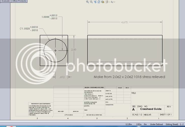
The critical dimensions are in bold with tolerance called out. In general for the other dimensions .xx plus minus .010; .xxx plus minus .005. THis is for the beginnings of a crosshead guide for a steam locomotive. I would rather NOT do it on the lathe because it is odd shaped and there in no way to support one end unless i make some sort of carrier fixture that steady rest can handle, not to mention chucking in the four jaw chuck (not too happy about this whole way of doing it.)
I have in mind a boring head on my manual mill. NOTE: I do not have a power downfeed for the mill.
I realize I CAN do it on the lathe if I clamp the workpiece to the cross slide at just the right height with shims and packing material (after taking a bunch of stuff off); and then bore with dog driven boring bar supported between centers (still don't like it). Only advantage is power feed on lathe since I have no power downfeed for my mill. Thanks.
[Edit] Bear in mind I want to make four of them. Two steel, two bronze. So I want to setup so as to be able to repeat fairly easily with fixtures etc, hopefully. If the stock comes from the mill fairly accurately sized I want to avoid squaring up the stock on the mill. If I have to square up I might farm that out where I buy it, so I can do other important stuff meantime. Maybe I'll have to, dunno. Will cut the first one or two in aluminum as a trial, then go with the steel , finally the last two I would like bronze if possible; so the setup has got to work really well because the bronze is $65 each for the part blanks.
I suspect it would be a good idea to get the bores close, say within .002 undersize and hone from there to bring the bore to size. Need advice on how to go about doing that.
Again Thanks for your time everyone.
regards, John
 
Use the boring head on the mill. You can make a crude power feed with a pulley and weight on the Z feed. Just a thought.
 
I would clamp it to the cross slide and use a between centres boring bar, I've used this method a couple of times on hit and miss cylinder liners of similar length and bore.

The problem with using a boring head is the tool gets quite long and starts to chatter and you also risk a tapered bore, plus getting a constant feed is not easy unless you have power feed on the mill.

J
 
Hi John,

My 1st thought is how much Z travel does your mill have? Because you need the 4.875" plus a bit for clearance top and bottom of the bore.

2nd Unless you have a decent size mill the boring bar in the boring head is going to be pretty flimsy at a length around 5.5"

Using a lathe, fixed steady and an offset collar you should be able to get a pretty substantial boring bar to do the job. Your lathe will also need to be a decent size or the fixed steady will not have the capacity to take the collar.

Hope this helps

Best Regards
Bob
 
Does your lathe cross-slide have a boring table, i.e. a machined top surface and t-slots? If so, a between-centres boring bar would be my strong preference. (Actually, in my case it would be the only sensible way, as I have no miller.)
 
between centers boring bar probably the way to go . the other option is mount the piece in the lathe with 4 jaw chuck and bore it out with a 1" boring bar.
the other thing you may want to do is just clean up the block in the mill first then bore the hole then finish the outer dimension that way you can adjust position and parallel if needed.
Tin
 
could u mount the part in the lathe cross slide and use your boring head in the chuck?
 
I would be inclined to mill the outside then mount the part on the cross slide of a lathe, shim into position, as you said previously to get it perfectly parallel then make a bar which mounts in the chuck or collet, supported the other end by a live centre. This bar will need a hole in it for a tool to mount (which can be adjusted to obtain size) and line bore as such. I believe that this would be the most sensible way providing there is mounting provisions on the cross slide.

By machining it this way there is a smaller chance of chatter, taper, poor finish and attempting the task several times.

I have used this technique hundreds of times during my machining life on both very large down to similar sized parts and think it is a very effective and accurate providing you be careful to set the job up spot on before going ahead.

I would definitely steer away from a dog driven bar between centres as to get a good finish you may need a fair rpm.

This is my opinion and everybody has a different technique, often achieving the same result.

Good luck, please post the outcome.

Baz.
 
I'd go with Tin's approach. Get the hole bored in a larger piece of stock however you can best do it. Then use a pin through the hole to locate it in the mill to cut the outside square to size. That way the hole will be parallel to the outside faces.
 
Thanks everyone!
Well it was late last night so I forgot to mention key points:
The mill has quite a bit of reach in z... 12 inches, so a boring head could go down through and back up and clear the part.
Second. The 9 x 30 lathe does not have t slots on the cross slide. I asked about getting a second cross slide (so I could keep the orginal intact) when I bought the Lathemaster, but the fellow who sells them said "Naw, It's nearly impossible to get one". I had thought of this problem back then. But I have not come up with a solution yet. Heck I just might send the crossheads out for boring if the price is right. This what I get for buying a lathe that is too small. Do you guys think this sort of thing might work:
PixC.jpg

Looks as though he just took the compound off and mounted a fabricated plate.
 
here's my compound & cross slide; (by the way that's preservative, not rust! ; when this photo was taken a time ago):
CompoundCrosslide.jpg

I guess what I could do is to buy one of these
A11-1.jpg

from http://www.statecollegecentral.com/metallathe/A-11.html
and machine the dovetails etc. to make a replacement. It's a 1/4" shorter in width and 1 " longer than mine. It's also 1/4 thicker than mine, which is a good thing, more or less.
The replacement seems to have enough meat, I think. It's definitely a time consuming one-off custom job. I might even farm it out to a professional shop after I come up with all the SolidWorks prints and everything. What does everybody think?
 
Why not drill/ream the hole on a square peice on a mill and then mill down one side?

Update: I just took a 2nd look at the drawing. My solution would take a really big drill and ream...LOL.
 
One of the basic fundamentals of machining is the the 2 1/2 rule of thumb. work should not stick out from the chuck more than 2 1/2 times the diameter of the work. More than that it needs to be supported. the same goes for boring bars.

I personally would not want to have a 5 inch long 1/2 diameter or even 1 inch diameter whipping around in a boring head. Scary stuff.

even a stationary 1 " steel BB will have flex sticking out that far remember the 2 1/2 rule. A carbide 1" bar would work but $$$$ not in the budget for most home shop guys. A carbide bar can stick out 7 x diameter.
so for a solid no chatter no taper set up hold the bb between centers and the part on the cross slide.

the part will need to be rough bored to at least 1" or 1.125 before setting up this way.
tin
 
Why not drill/ream the hole on a square peice on a mill and then mill down one side?....
That's one of the problems. No 1 there's NO automatic downfeed on my mill. Therefore using a boring head with hand downfeed, there will be inconsistent SFM and feedrate so most likely there will be chatter, inconsistent bore size, and inconsistent surface finish because the pressure exerted on the tool is always changing. Secondly supporting the workpiece standing up on the mill vise is far less ridgid than clamping it down to the lathe cross slide (the method I'm seriously taking a look at). I would stand it up in the mill vise *IF* I had an auto downfeed like a Bridgeport. I think I could get away with it, or at least I'd try anyway. However that is not the case. This method of line drilling and using a boring bar mounted between centers (w/ part clamped to cross slide) has been used for decades upon decades- just I have never done it before or even seen someone actually do it, just read about it, that's all. It was very commonly used in Model Engineering in the last century up until maybe the 60's when mills became more affordable to Home Shop Machinists (people are still using this method though, just I don't hear about it much). If you look old issues of Model Engineer mag from the 30's, 40's and 50's, articles were written where the author(s) advised line boring between centers routinely because most guys didn't have a mill! Case-in-point: Edgar T. Westbury's articles.
So it appears I shall have to clamp the part down to the cross slide and use a boring bar between centers - "Smith Barney we make parts the old fashioned way...we earn them!" (just a small joke there).

Well, Tin Falcon, I think I'm going to establish a build thread on mounting a fabricated T-slot cross slide onto an Asian lathe! For it is there I must start, since it is necessary to have that in order to do the all important Live Steam crosshead guides; which again I point out, the bronze ones cost 65$ each just for the material.
 

Latest posts

Back
Top