- Joined
- Jul 16, 2007
- Messages
- 2,987
- Reaction score
- 1,055
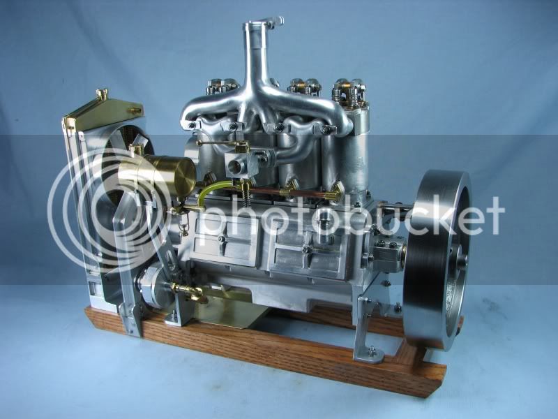
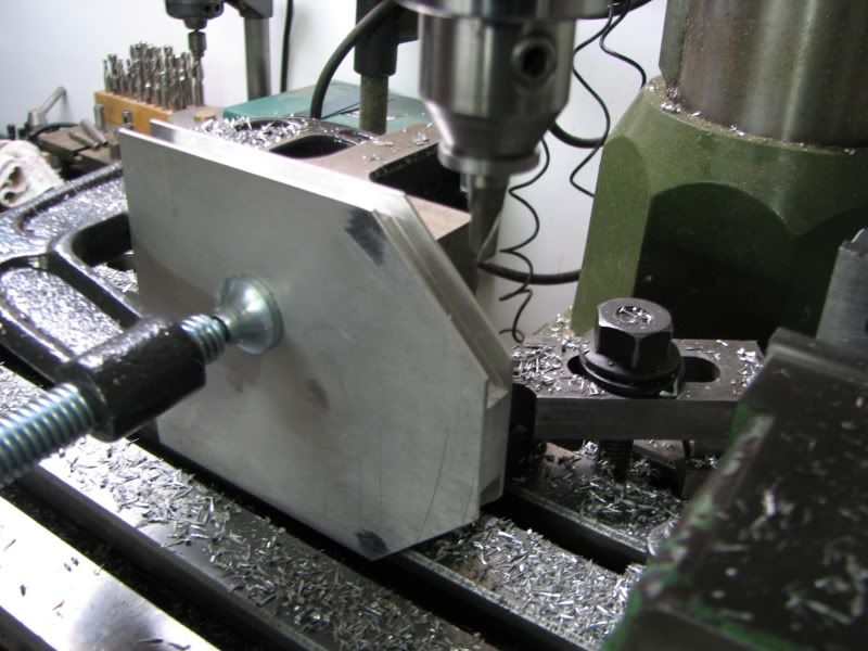
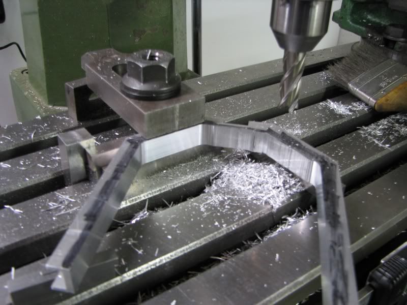
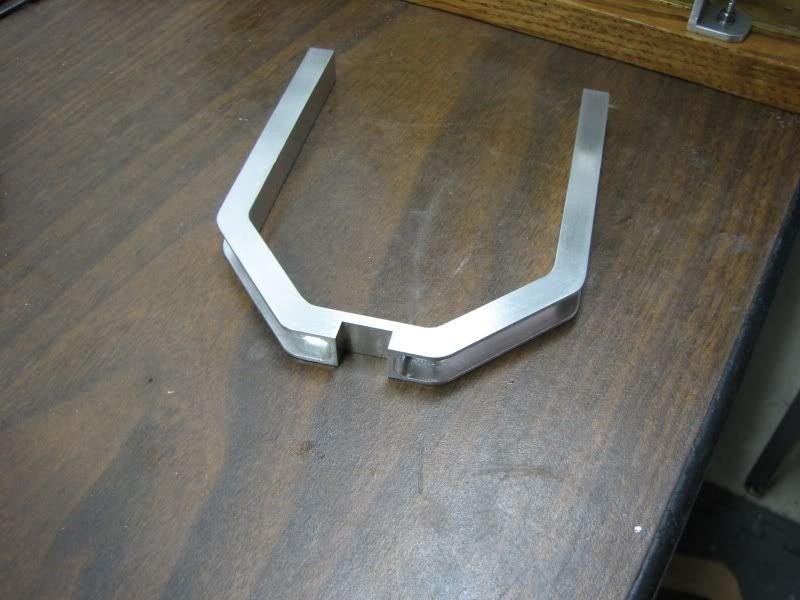
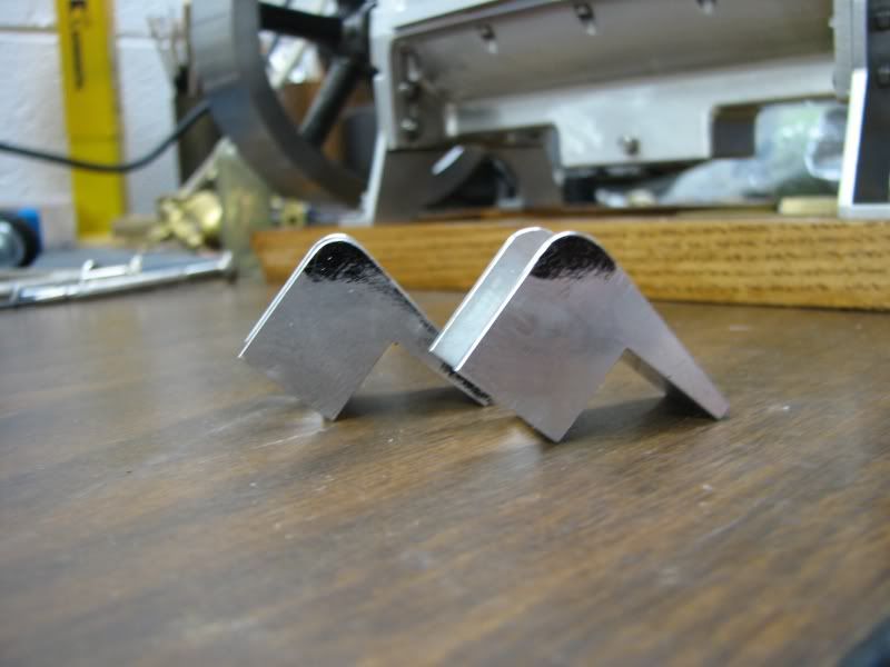
I had my Holt engine at the NAMES show last month. I ran it almost constantly for the 2 days. I can get about 5 minutes out of it before it gets quite warm. On several occasions people would ask if I could start it and I told them it had to cool down some so they asked why it didn't have a fan. I told them it was one of those things I had to get to since this engine is still a work in progress. Last week I finished up some projects and sat down and designed a fan and mounting system along with a shroud for the radiator. As everything else is built from billet aluminum this was no exception. I wanted it to look like it was part of the engine so I created little brackets and pieces to keep everything interesting. The first few pictures show the main support bracket being machined.
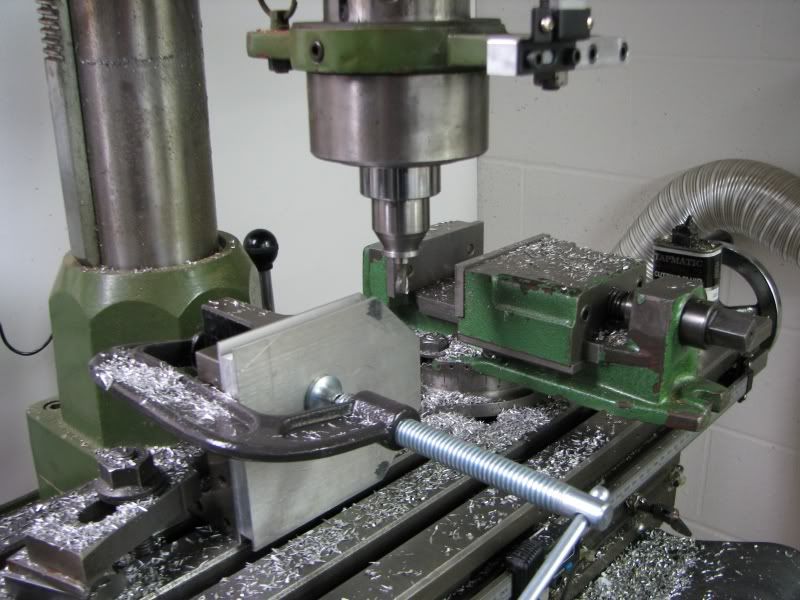
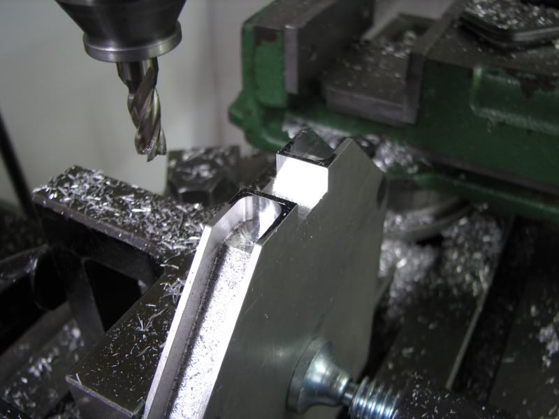
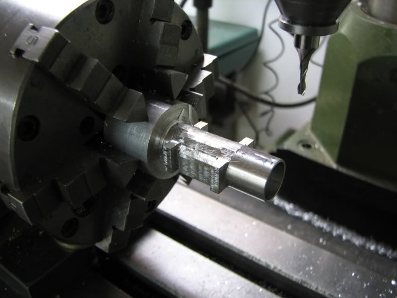
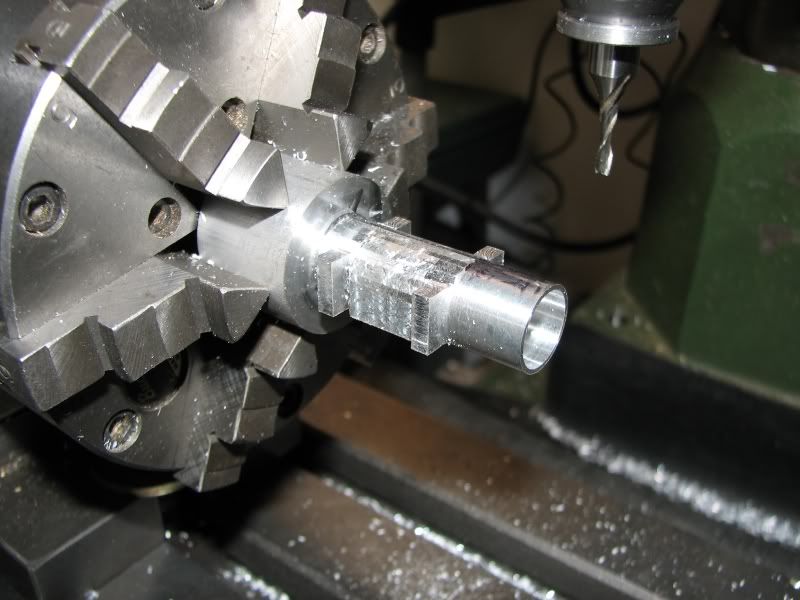
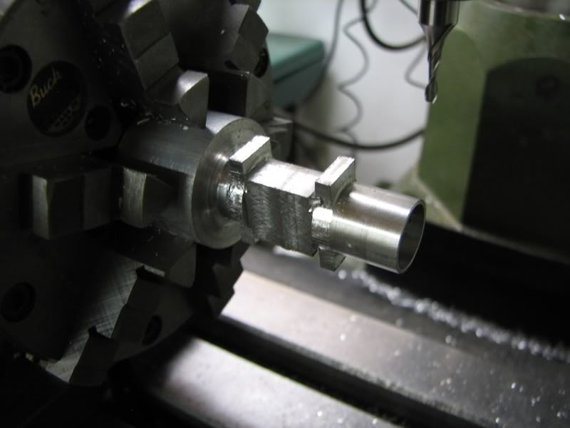
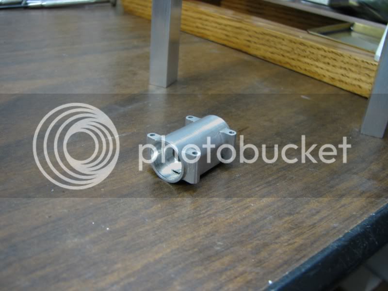
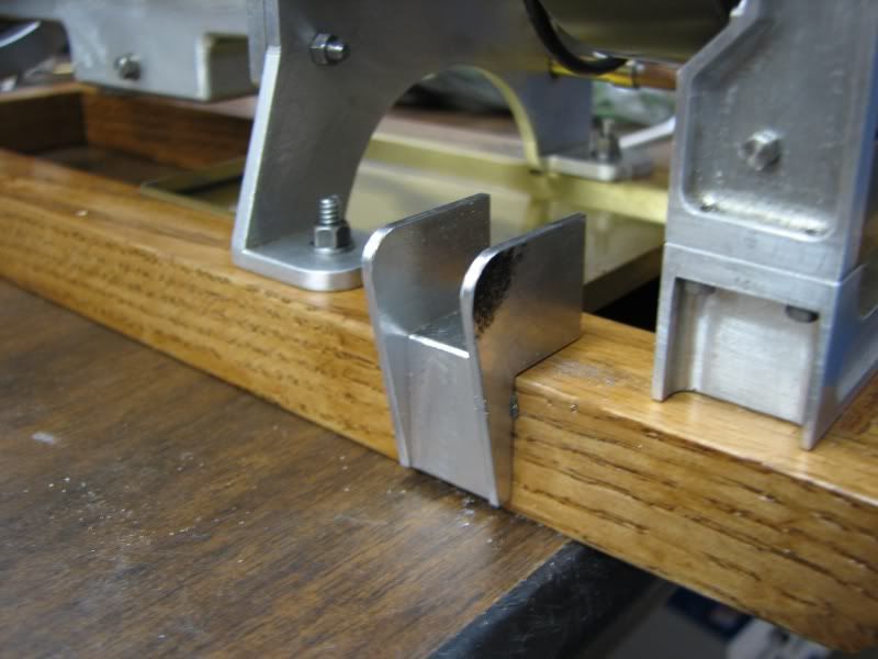
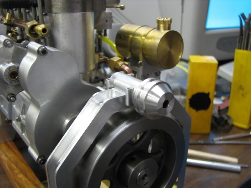
The next set of pictures show the bearing support being machined. I designed it for ball bearings because of the speed it might need to run. I also wanted it to look like something that might be found on the original so although it's one piece I added the bolt bosses to make it look like it was a split type housing. I drilled and counterbored one end for the bearing and left extra stock on it so that I could rechuck it in the lathe to counterbore the other end. I stepped around the bosses and used the diameter of the extra stock to cut the radial shape on the top. The bottom is square so that it locates in the notch in the upright frame. It has one 6-32 flathead screw from the bottom to hold it together. It can't go anywhere because it fits snuggly in the notch. After machining I filed and sanded everything up.
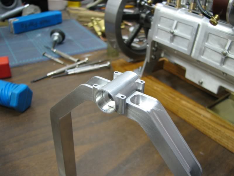
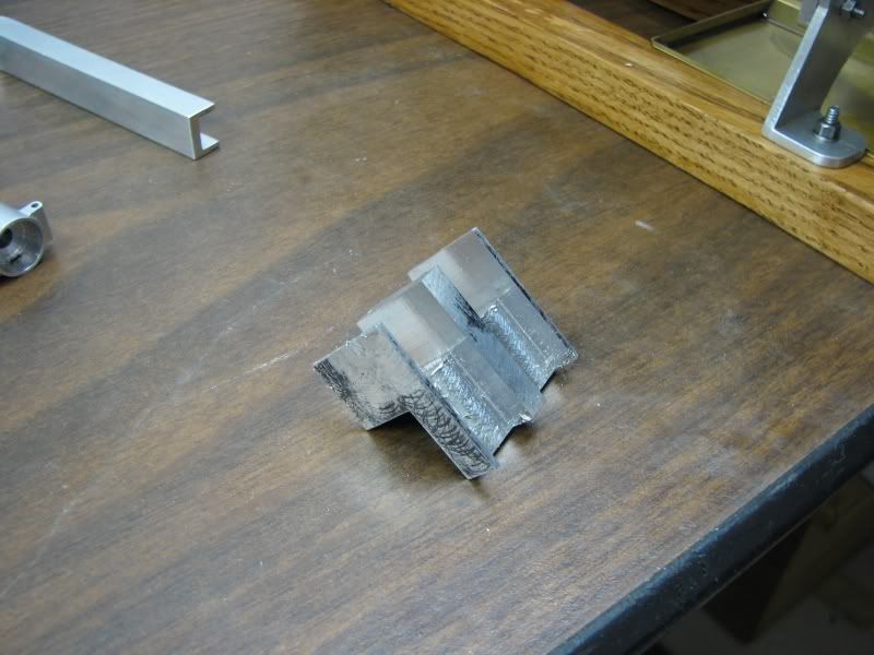
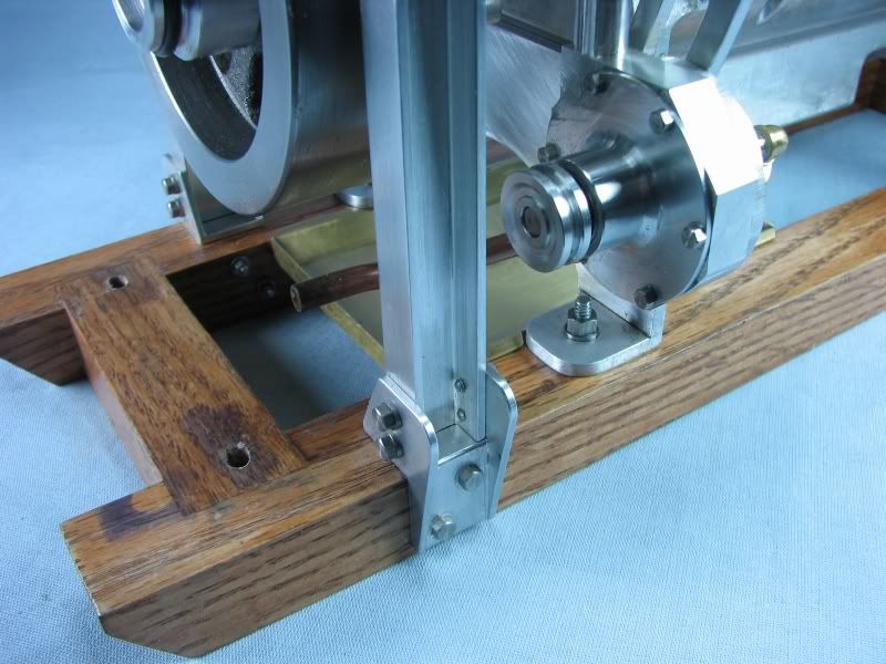
Next came the mounting brackets to hold the upright to the wooden frame that the engine sits on. Not much to say about this operation, just machining aluminum bar stock.

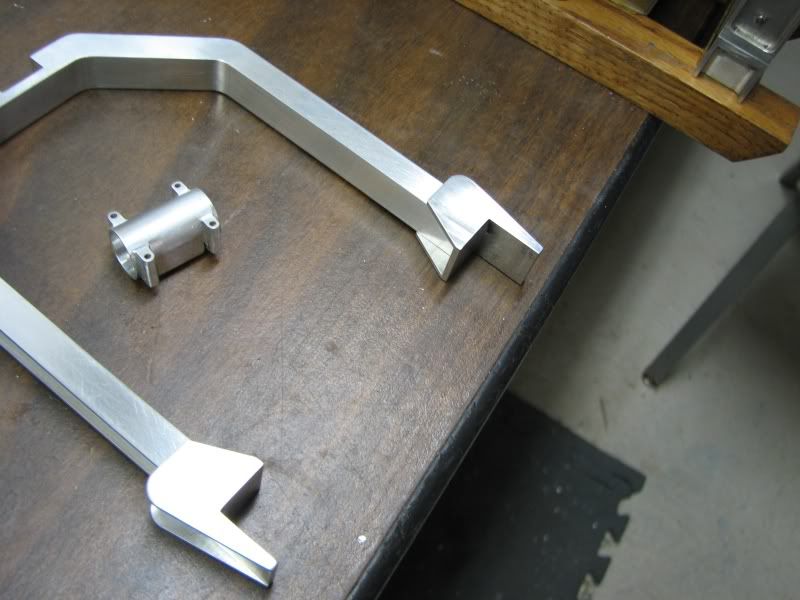
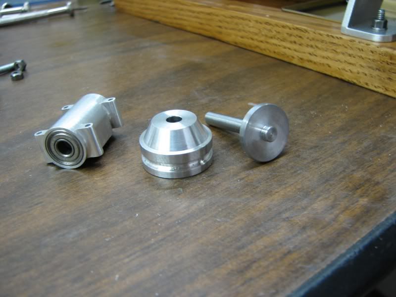
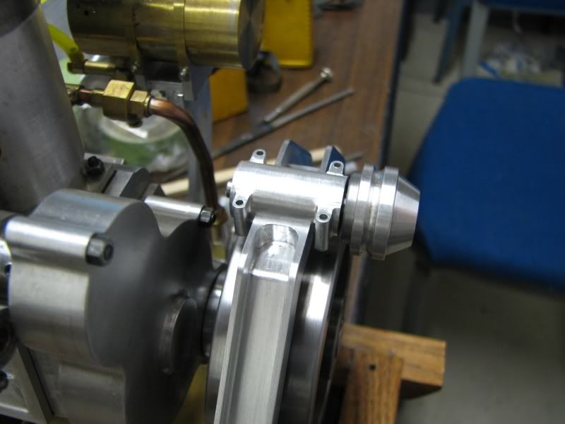
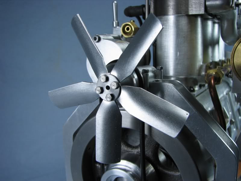
Next came the spindle, pulleys and fan. The spindle is made from 12L steel and has a retainer with a set screw to hold it in place in the bearing support. The pulleys are aluminum and are grooved for the appropriate sized 'O' ring much like the water pump drive.
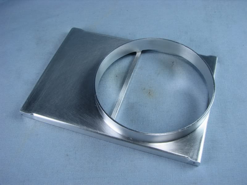
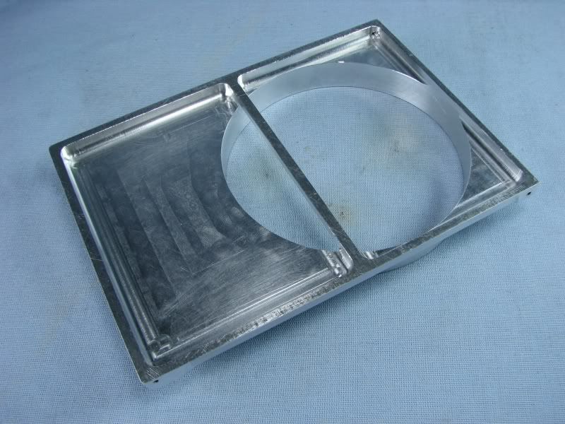
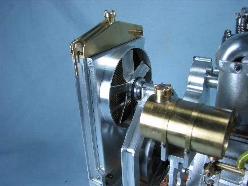
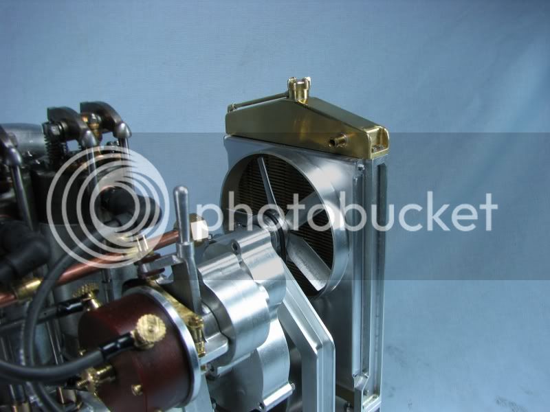
Next came the fan shroud. When I first made the radiator from the Jerry Howell design he showed a couple of little tabs on the support brackets for a fan shroud. At the time I wasn't going to put them on but I'm glad now that I did. I started with a rectangular piece of aluminum. I layed out the center of the fan location and mounted it in my 4 jaw chuck picking up the layed out center mark. I started turning the outside first because had I bored out the center first I was afraid that the pressure on the chuck jaws would have collapsed the side walls. It was a slow process because the part was so far off center that I took .030 cuts due to the intermittant cuts. Once I got close I took out the pointed tool and put in a radiused tool to finish up and put a fillet at the base of the circular area. I then started boring out the center. I only went deep enough to leave .125 in the bottom for the reason stated above. I knew that when I later machined the backside this extra stock would come out anyway. Once it was bored to size I removed it from the lathe and put it in the vise on the mill. I started cutting the back side out and left a bar across the center to help keep things ridgid. My buddy stopped over and was watching what I was doing and said "why don't you leave that bar in there, it looks like something they would have done when they made it". I agreed and that's why you see the bar there. After the back was cleared out I clamped it to my mill table and relieved the side with a 7 degree cutter and radiused the edges, except where it was going to mount to the radiator bracket. Some filing, sanding and polishing and this is the finished product. The only thing left was to drill and tap the mounting hole for it.
The final few pictures are with everything assembled. The only thing left to do is make new water lines because I had to move the radiator up and forward to get all this in.
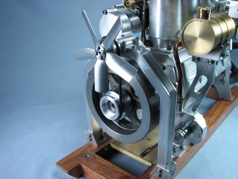
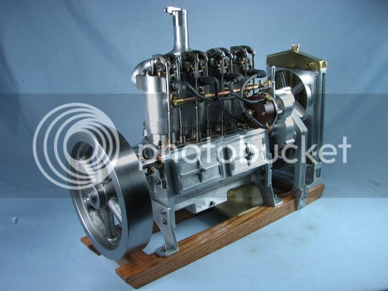
I think the Holt is just about finished. I just have to get my remade carb sorted out and she'll be done. I have thought about painting it like some of the others I've seen but I just like the look of the natural metal too much.
gbritnell
The next set of pictures show the bearing support being machined. I designed it for ball bearings because of the speed it might need to run. I also wanted it to look like something that might be found on the original so although it's one piece I added the bolt bosses to make it look like it was a split type housing. I drilled and counterbored one end for the bearing and left extra stock on it so that I could rechuck it in the lathe to counterbore the other end. I stepped around the bosses and used the diameter of the extra stock to cut the radial shape on the top. The bottom is square so that it locates in the notch in the upright frame. It has one 6-32 flathead screw from the bottom to hold it together. It can't go anywhere because it fits snuggly in the notch. After machining I filed and sanded everything up.
Next came the mounting brackets to hold the upright to the wooden frame that the engine sits on. Not much to say about this operation, just machining aluminum bar stock.
Next came the spindle, pulleys and fan. The spindle is made from 12L steel and has a retainer with a set screw to hold it in place in the bearing support. The pulleys are aluminum and are grooved for the appropriate sized 'O' ring much like the water pump drive.
Next came the fan shroud. When I first made the radiator from the Jerry Howell design he showed a couple of little tabs on the support brackets for a fan shroud. At the time I wasn't going to put them on but I'm glad now that I did. I started with a rectangular piece of aluminum. I layed out the center of the fan location and mounted it in my 4 jaw chuck picking up the layed out center mark. I started turning the outside first because had I bored out the center first I was afraid that the pressure on the chuck jaws would have collapsed the side walls. It was a slow process because the part was so far off center that I took .030 cuts due to the intermittant cuts. Once I got close I took out the pointed tool and put in a radiused tool to finish up and put a fillet at the base of the circular area. I then started boring out the center. I only went deep enough to leave .125 in the bottom for the reason stated above. I knew that when I later machined the backside this extra stock would come out anyway. Once it was bored to size I removed it from the lathe and put it in the vise on the mill. I started cutting the back side out and left a bar across the center to help keep things ridgid. My buddy stopped over and was watching what I was doing and said "why don't you leave that bar in there, it looks like something they would have done when they made it". I agreed and that's why you see the bar there. After the back was cleared out I clamped it to my mill table and relieved the side with a 7 degree cutter and radiused the edges, except where it was going to mount to the radiator bracket. Some filing, sanding and polishing and this is the finished product. The only thing left was to drill and tap the mounting hole for it.
The final few pictures are with everything assembled. The only thing left to do is make new water lines because I had to move the radiator up and forward to get all this in.
I think the Holt is just about finished. I just have to get my remade carb sorted out and she'll be done. I have thought about painting it like some of the others I've seen but I just like the look of the natural metal too much.
gbritnell