Hoglet in progress

Home Model Engine Machinist Forum

Help Support Home Model Engine Machinist Forum:

This site may earn a commission from merchant affiliate links, including eBay, Amazon, and others.

MatiR

Well-Known Member
Joined
Jul 10, 2007
Messages
65
Reaction score
7
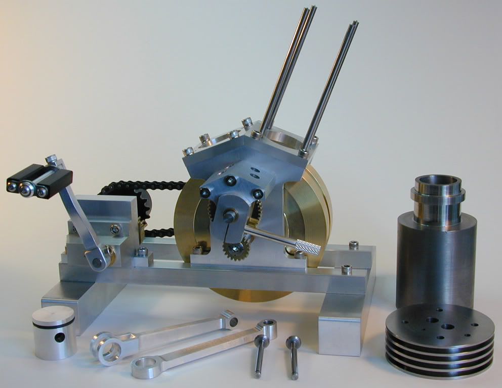
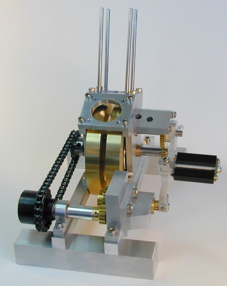
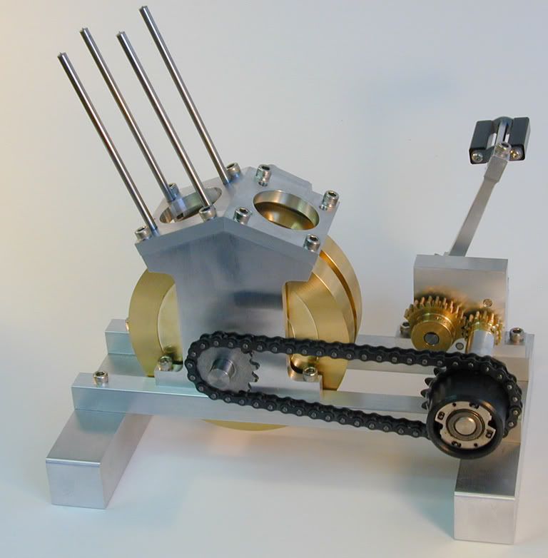
Had my camera at home after all; though that I had taken it to work. As promised in my recent Upshur Twin thread, here are some quick pics of the Hoglet in progress. Plans are from Model Engine Builder magazine after the design of Randall Cox. I changed the fly wheel design to single disks from the two part design in the plans. I like the original design better, but was beyond the capability of my lathe. Still lots of work to do, especially the rather large cylinders (one shown) which will have to be done on a larger lathe than my Sherline. I managed to machine the bottom of one cylinder, but only with difficulty. The cooling fins and grooves are not possible. The cylinder heads also need intake, exhaust and spark plug ports. The Robertson screws on the front of the cam housing are placeholders until I can get some decent socket caps in that length.

Regards, Mati

HogletFront.jpg


HogletLeftSide.jpg


HogletRear.jpg

 
Mati,

Thats pretty good looking so far. Is that pedal a kick starter? What issues are the plans in?

Thanks
Eric
 
You are doing a great job!!! I cant wait to see how it turnes out:eek:)

Wes
 
Eric, the plans are in MEB 2007 Issues 10 and 11. Yes that's a kick starter and it was quite a chore to build with the arm having compound curves. I haven't made the flat spring which tensions the arm. The black cylinder with the sprocket at the rear is a slip clutch so when the engine starts, it just freewheels.

M.
 
Very nice!

Just curious what you used for the fly wheels. I think the plans call for bronze and I priced the hollow round and it was fairly expensive. Did you just take a deep breath and pony up the dough for large round stop of brass or bronze?

I've started building the Hoglett as well. I'm not nearly as far along as you. I will start a new thread in the "in process" section soon.

The fit is really good. Maybe you have a trick but I had a heck of a time with the angles on some of the pieces I've made so far. I always enjoy pictures of projects. Very nice work!
 
Thanks Jadecy and others. The flywheels are brass and I just ponied up for two cuts close to the finished size from Online metals - I don't have any way to cut something like these at home. In spite of their size, they machined up very nicely on the Sherline with riser blocks.

I was very pleased with the fit of the angled parts. For the crankcase I made a triangular piece of aluminum plate with the 21 degree angle and used that in the mill vise to set the proper angles. For the camshaft housing, I made a fixture according to the MEB plans and used that in my chuck/rotary table mounted at 90 degrees on an angle plate to machine the angles and drill the holes for the lifters.

I look forward to seeing your thread.

M.
 
Just for reference, how big are the flywheels?

Thanks, Wes
 
Very nice looking engine and excellent job on the machining. I also like the quality of the pictures, nice and clear and well lighted. Keep up the great work.

Bernd
 
Wes, the flywheels are nominally 4.050 x 0.563 inches, but as I started with 4.000 stock, mine are a few thou undersize in diameter. Thanks, Bernd - its been a struggle at times, but educational and fun.

M.
 
What size chain did you use. If it is smaller than 25 what is your source.
 
Nice. How do you get that finish? My parts come off the mill slightly less pretty, no matter the feeds and speeds.

E
 
Nice work ! Do you have all the electrics already? not much is mentioned in the plans or magazines in regards to the coil set-up etc. besides magnet placement. (that i noticed) I just started this engine as well and hope it comes along as nice as yours. Did you use the comercial parts suggested in the prints and what were your sources? I suppose 4.050 bronze is what Randall had laying around because .025 per side couldn't matter that much, could it? sure beats taking a 1/4 inch off. Excellent photo's is the backdrop rigid, or fabric? They look real professional.I look forward to more progress pics!
-Kevin-
 
Answers to a few questions from above:

“What size chain did you use. If it is smaller than 25 what is your source.”

The chain is 0.25 pitch from Small Parts I think but it is readily available elsewhere.

“Nice. How do you get that finish? My parts come off the mill slightly less pretty, no matter the feeds and speeds.”

“I usually finish all milled parts with some 320 wet/dry paper and sometimes 400 or 600, but 320 is generally fine.”


“Nice work ! Do you have all the electrics already? not much is mentioned in the plans or magazines in regards to the coil set-up etc. besides magnet placement. (that i noticed) I just started this engine as well and hope it comes along as nice as yours.”

I haven’t got a clue what to do with the electrics. I was thinking of asking Mike Neal at MJN Fabrication for advice – he was very helpful and provided a CDI module for the Upshur twin which sparks nicely but I haven’t fueled it up. Perhaps I can use that also for the Hoglet (it came with a bunch of little magnets).

“Did you use the comercial parts suggested in the prints and what were your sources?”

Yes, I used most of the commericial parts suggested and generally ordered them from the same places except for McMaster who will not ship to Canada any more. Boston gears I got locally.

“Excellent photo's is the backdrop rigid, or fabric? They look real professional.I look forward to more progress pics!”

Nothing fancy here – just some curved white Bristol board propped up against something and a several incandescent desk lamps to distribute the light evenly with a bright window nearby. Levels slightly adjusted with Photoshop. The camera is an ancient Nikon 950 Coolpix from work which is only 2.1 megapixel but has a superb lens.

Thanks for the interest, M.
 
I just noticed your in Vancouver, I live in Richmond, we order from McMaster at work all the time. And get things usually the next day.What did they tell you? I'm actually modelling some of the parts right now. Just finished the cam housing. What fun.
normal_cam_housing.jpg
 
McMaster sent the following:

"Due to the ever-increasing complexity of U.S. Export regulations,
McMaster-Carr has decided to only accept orders from a few,
long-established customers of ours overseas. We cannot accept your
order, and regret any inconvenience this causes you."

I guess that they are maintaining their regular commercial clients but will not deal with miscellaneous small time orders. By overseas, I assume they mean foreign unless whoever sent this message failed geography at some point :)

Yes, that cam housing was fun. Mine came out nicely except that one of the lifter holes is about 0.5 degrees off but there is enough tolearance so not likely to be a probem. Nice drawing - is that Alibre? I have the free version and have been trying to get up to speed but am still making sketches with a pencil for now.
 
Thanks, I just drew it in Mastercam, I have solidworks but can't work it as well. That's too bad about Mcmaster because they have alot of stuff and I won't be ordering personal stuff through work, Oh well, Action bearings should have everything I'll need.
-Cheers
 
Hey MatiR,

Have you made your cam yet? Are you going to go with the 4 lobe as suggested in the magazine? If so do you have a sketch you wouldn't mind sharing. Is the timing gear lok-tited to the shaft? In the mag pics he has what looks like a one-piece plate holding the coil. Is the spark generated by the "hall effect" or does he have a battery hidden in the base? I found a piece of 1/8 spring steel if you are having trouble locating some.
Lots of questions but if you have been through all this already it would be a big help.
Thanks,
-Kevin.
 
Hi Kevin:

No, I haven't thought about the camshaft yet and it will probably be some time before I get that far. I expect that the gear would be fastened with loctite - I see no other way to do it. I was thinking of doing the 3 lobe version just to keep thinks simple at first. I used the drawings without circular coil attachment to make the kicker frame, planning to have a separate ignition setup and I am quite ignorant now as to how to proceed with that. Also, I did not cut the radius for the coil yet. Will have to live and learn as it progresses. Right now I am struggling with the cylinder heads. Before proceeding with the heads, carefully plot out the drawings as it is impossible to drill 1/4 holes for the exhaust outlet that clear the top rim of the 21 degree counter bores as shown in the plans. I don't think that I have screwed up here but I went with 3/16 and had to mill some clearance to the adjacent cooling fin. The plans and engine photographs are not identical. I'm planning on doing some more work this weekend so I'll report back when I can.

M.
 

Hi Mati,

I just got back onto my twin and was wondering how progress on yours is coming along?

Kevin.
 
Do you guys recommend the MEB magazine drawings or the plans directly from Randall Cox? Is there any difference? This design is one (of many) I'd like to build but have yet to acquire the plans.
Thanks
Garry
Penticton, British Columbia
 
Back
Top